
Related Manuals for Shuttle AV18


Summary of Contents for Shuttle AV18
- Page 1 AV18 FC-PGA/PPGA Celeron and FC-PGA Pentium III processor Based AGP MAIN BOARD User's Manual...
- Page 2 Shuttle Inc. Disclaimer Shuttle Inc. shall not be liable for any incidental or consequential damages resulting from the performance or use of this product. This company makes no representations or warranties regarding the contents of this manual.
-
Page 3: Table Of Contents
2.1 SPECIFICATIONS ....................7 3 HARDWARE INSTALLATION ............. 10 3.1 STEP BY STEP INSTALLATION ............... 10 Accessories Of AV18 ..................10 STEP 1 Install the CPU ..................11 STEP 2 Set Jumpers ..................12 STEP 3 Install SDRAM System Memory ............12 STEP 4 Install Internal Peripherals in System Case ........ - Page 4 STEP 11 Connect External Peripherals to Back Panel ........ 20 STEP 12 First Time System Boot Up ............. 22 STEP 13 Install Drivers & Software Components ......... 23 3.2 JUMPER SETTINGS ................... 24 Jumpers & Connectors Guide ................. 25 EEPROM FLASH BLOCK LOCK (JP6) ............27 CPU Clock Ratio Setting (JP4) ...............
- Page 5 3.3 SYSTEM MEMORY CONFIGURATION ............39 Install Memory....................39 Upgrade Memory ....................39 4 SOFTWARE UTILITY ................40 4.1 AV18 MAINBOARD CD OVERVIEW ............... 40 4.2 INSTALL MAINBOARD SOFTWARE .............. 41 4.3 INSTALL Audio Device SOFTWARE .............. 42 4.4 INSTALL VIA Hardware Monitor ..............43 4.5 TO VIEW THE USER'S MANUAL ..............
-
Page 6: What's In The Manual
WHAT’S IN THE MANUAL Quick Reference Hardware Installation >> Step-by-Step ............Page 10 Jumper Settings >> A Closer Look ............Page 24 Software Utility >> How to Install ..............Page 40 BIOS Setup >> How to Configure ............... Page 45 About This Manual For First-Time DIY System Builder ..............Page 5 For Experienced DIY User ................Page 5... -
Page 7: Introduction
Experienced DIY User Congratulations on your purchase of the Shuttle AV18 mainboard. You will find that installing your new Shuttle AV18 mainboard is just that easy. Bundled with an array of onboard functions, the highly-integrated AV18 mainboard pro- vides you with a total solution to build the most stable and reliable system. -
Page 8: Item Checklist
1.2 Item Checklist Check all items you received with your AV18 mainboard to make sure nothing is missing. The complete package should include: - One Shuttle AV18 Mainboard A W A R D A l l r i g h t s r e s e r v e d... -
Page 9: Features
2 FEATURES The AV18 mainboard is carefully designed for the demanding PC user who wants high performance and maximum intelligent features in a compact package. 2.1 Specifications - - CPU Support Support Intel FC-PGA/PPGA Celeron Processor 300 ~ 600+ MHz... - Page 10 - - Super I/O Chip Provides a variety of I/O interfaces: Ø 1 × Floppy interface for 3.5-inch FDD with 720KB, 1.44MB, 2.88MB format or for 5.25-inch FDD with 360KB or 1.2MB format. Ø 1 × PS/2 mouse connector Ø 1 × PS/2 Keyboard connector Ø...
- Page 11 - - ATX Form Factor System board conforms to the ATX specification. Board dimensions: 304mm × 190mm - - Advanced Features Ø Dual Function Power Button - The system can be in one of two states, one is Suspend mode and the other is Soft-Off mode. Pushing the power button for less than 4 seconds places the system into Suspend mode.
-
Page 12: Hardware Installation
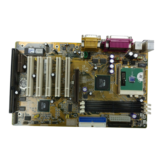
3 HARDWARE INSTALLATION This section outlines how to install and configure your AV18 mainboard. Refer to the following mainboard layout to help you identify various jumpers, connectors, slots, and ports. Then follow these steps designed to guide you through a quick and correct installa- tion of your system. -
Page 13: Step 1 Install The Cpu
Step 1 Install the CPU: 1. Locate the CPU ZIF (Zero Insertion Force) socket on the upper-right sector of your mainboard (between the back-panel connectors and the DIMM memory banks). 2. Pull the CPU ZIF socket lever slightly sideways away from the socket to unlock the lever, then bring it to an upward vertical position. -
Page 14: Step 2 Set Jumpers
Step 2. Set Jumpers This mainboard is jumperless! The default jumper settings have been set for the common usage standard of this mainboard. Therefore, you do not need to reset the jumpers unless you require special adjustments as in any of the following cases: 1. -
Page 15: Step 4 Install Internal Peripherals In System Case
Step 4 Install Internal Peripherals in System Case Before you install and connect the mainboard into your system case, we recommend that you first assemble all the internal peripheral devices into the computer housing, including but not limited to the hard disk drive (IDE/ HDD), floppy disk drive (FDD), CD-ROM drive, and ATX power supply unit. -
Page 16: Step 5 Mount The Mainboard On The Computer Chassis
Step 5 Mount the Mainboard on the Computer Chassis 1. You may find that there are a lot of different mounting hole positions both on your computer chassis and on the mainboard. To choose a correct mounting hole, the key point is to keep the back-panel of the mainboard in a close fit with your system case, as shown below. -
Page 17: Step 6 Connect Front Panel Switches/Leds/Speaker
Step 6 Connect Front Panel Switches/LEDs/Speaker You can find there are several different cables already existing in the system case and originating from the computer’s front-panel devices (HDD LED, Power LED, Reset Switch, PC Speaker, etc.) These cables serve to connect the front-panel switches and LEDs to the mainboard’s front-panel connectors group, as shown below : SPEAKER... - Page 18 4. HDD-LED (HDLED) SPEAKER POWER LED HDLED GLED EPMI PWON 5. Hardware Reset Switch (RST) SPEAKER POWER LED HDLED GLED EPMI PWON 6. PC Speaker (SPEAKER) POWER LED SPEAKER HDLED GLED EPMI PWON 7. POWER LED (POWER LED) POWER LED SPEAKER HDLED GLED EPMI PWON - 16 -...
-
Page 19: Step 7 Connect Ide & Floppy Disk Drives
Step 7 Connect IDE & Floppy Disk Drives 1. IDE cable connector IDE 1 IDE 2 2. Floppy cable connector FDC 1 - 17 -... -
Page 20: Step 8 Connect Other Internal Peripherals
Step 8 Connect Other Internal Peripherals 1. IR connector Step 9 Connect the Power Supply 1. System power connector - 18 -... -
Page 21: Step 10 Install Add-On Cards In Expansion Slots
Step 10 Install Add-on Cards in Expansion Slots 1. Accelerated Graphics Port (AGP) Card 2. PCI Card 3. AMR Card 4. ISA Card - 19 -... -
Page 22: Step 11 Connect External Peripherals To Back Panel
Step 11 Connect External Peripherals to Back Panel You are now ready to put the computer case back together and get on to the external peripherals connections to your system’s back-panel. KEYBOARD & MOUSE USB PORT COM2 COM1 PRINT 1. PS/2 Mouse and PS/2 Keyboard PS/2 Mouse PS/2 keyboard 2. - Page 23 4. Parallel Port Parallel Port 5. Audio Line_Out/Line_In/Mic_In Line_Out Line_In Mic_In 6. MIDI/Game Port MIDI/GAME Port - 21 -...
-
Page 24: Step 12 First Time System Boot Up
Step 12 First Time System Boot Up To assure the completeness and correctness of your system installation, you may check the above installation steps once again before you boot up your system for the first time. 1. Insert a bootable system floppy disk (DOS 6.2x, Windows 95/98/NT, or others) which contains FDISK and FORMAT utilities into the FDD. -
Page 25: Step 13 Install Drivers & Software Components
Make sure your Windows 9x operating system is already installed before running the drivers installation CD-ROM programs. Insert the AV18 bundled CD-ROM into your CD-ROM drive. The auto-run program will display the drivers main installation window on screen . -
Page 26: Jumper Settings
3.2 Jumper Settings Several hardware settings are made through the use of jumper caps to con- nect jumper pins on the mainboard. Pin #1 is located at any corner of each jumper, you just find a white right angle on the mainboard, that's pin 1#. There are several types of pin1# shown as below: 3-pin and multi (>3) pin jumpers shown as following: Pin #1 on the left:... -
Page 27: Jumpers & Connectors Guide
Jumpers & Connectors Guide Use the mainboard layout on page 10 to locate CPU socket, memory banks, expansion slots, jumpers and connectors on the mainboard during the instal- lation. The following list will help you to identify jumpers, slots, and connec- tors along with their assigned functions: B3~B5 B6~B9... - Page 28 Jumpers : EEPROM Block Lock : CPU Clock Ratio Setting : Clear CMOS : System Frequency Configuration Back Panel Connectors : PS/2 Keyboard : PS/2 Mouse : 2 × USB (Universal Serial Bus) COM2 : Serial Port 2 (DB9 male) PRINTER : Parallel Port (DB25 female) COM1...
-
Page 29: Eeprom Flash Block Lock (Jp6)
(Lock BIOS Flash) CPU Frequency Ratio Configuration (JP4) AV18 mainboard provides a jumper group JP4 to set CPU frequency ratio configuration by BIOS or by hardware jumper. By inserting mini jumpers on JP4 properly, the user can configure the CPU Clock Ratio manually. -
Page 30: Clear Cmos (Jp2)
Clear CMOS (JP2) JP2 is used to clear CMOS data. Clearing CMOS will result in permanently erasing the previous system configuration settings and restoring the original (factory-set) system settings. Pin 1-2 (Default) Pin 2-3 (Clear CMOS) Step 1. Turn off the system power (PC-> Off) Step 2. -
Page 31: System Frequency Configuration (Jp7)
System Frequency Configuration (JP7) AV18 provides jumper JP7 to set auto configure front side bus at 66MHz, 100MHz and 133MHz. Inserting mini jumpers Pin 5-6 & 7-8 on JP7 as below to identify automatically the FSB speed. Default (Auto Configure) -
Page 32: Ps/2 Keyboard & Ps/2 Mouse Connectors
PS/2 Keyboard & PS/2 Mouse Connectors Two 6-pin female PS/2 keyboard & Mouse connectors are located at the rear panel of the mainboard. Depending on the com- PS/2 Mouse puter housing you use (desktop or minitower), the PS/2 Mouse connector is situated at the top of the PS/2 Keyboard connector when the mainboard is laid into a desktop, as opposed to a minitower... -
Page 33: Line-Out And Line-In And Mic-In Header
Line_Out Line_Out is a stereo output port through which the combined signal of all internal and external audio sources on the oard is output. It can be con- nected to 1/8-inch TRS stereo head- Line_Out phones or to amplified speakers. Line_In Line_In is a stereo line-level input port that acdepts a 1/8-inch TRS stereo... -
Page 34: Hardware Reset Connector (Rst)
Hardware Reset Connector (RST) Attach the 2-pin hardware reset switch cable to the RST header. Pressing the reset switch causes the system to restart. POWER LED SPEAKER HDLED GLED EPMI PWON HDD LED Connector (HDLED) Attach the connector cable from the IDE device LED to the 2-pin HDD LED header. -
Page 35: Atx Power On/Off Switch Connector (Pwon)
ATX Power On/Off Switch Connector (PWON) The Power On/Off Switch is a mo- mentary type switch used for turn- ing on or off the system’s ATX power supply. Attach the connector cable from the Power Switch to the 2-pin POWER LED SPEAKER PWON header on the mainboard. -
Page 36: Enhanced Ide And Floppy Connectors
Enhanced IDE and Floppy Connectors The AV18 mainboard features two 40-pin dual-channel IDE device connec- tors (IDE1/IDE2) providing support for up to four IDE devices, such as CD- ROM and Hard Disk Drives (H.D.D.). This mainboard also includes one 34- pin floppy disk controller (FDC) to accommodate the Floppy Disk Drive (F.D.D.). -
Page 37: Audio Connector Cd_In (Jp10)
4=Left Channel Audio TAD I/O Header (JP11)(GREEN) Port JP11 can be used to connect a modem audio line to AV18 mainboard. Typically, you would use this connector when running the voice mail soft- ware on your system for audio input and output. -
Page 38: External Usb Ports (Jp5)
External USB Ports (JP5) This header is used to connect the cable attached to USB connectors mounted on front panel or back panel. But the USB cable is optional at the time of purchase. EXT USB PORT IR Connector (JP1) If you have an Infrared device, this mainboard can implement IR transfer function. -
Page 39: Wake-On Lan Connector (J2)
Wake-on LAN Connector (J2) Attach a 3-pin connector from the LAN card which supports the Wake-On- LAN (WOL) function. This function lets users wake up the connected system through the LAN card. Wake On Lan CPU, Cooling Fan Connectors (FAN1, FAN2, FAN3) The mainboard provides three onboard 12V cooling fan power connectors to support CPU (FAN1), System (FAN2) and AGP (FAN3) cooling fans. -
Page 40: Atx Power Supply Connector (Atx Pwr)
ATX Power Supply Connector Locate the 20-pin male header ATX power connector (ATX PWR) on your mainboard. Plug the power cable from the ATX power supply unit directly into ATX PWR ATX power supply connector. Note 1 :The ATX power connector is directional and will not go in unless the guides match perfectly. -
Page 41: System Memory Configuration
Checking) and ECC (Error Checking and Correction) in the memory array. In EC mode, single and multiple bit error detection is provided. In ECC mode, when the memory is being read from DRAM, the AV18 provides both error checking and correction of the data. -
Page 42: Software Utility
Install VIA Hardware Monitor - Installing VIA Hardware Monitor Driver Manual - AV18 series mainboard user's manual in PDF format. Link to Shuttle Homepage - Link to shuttle website homepage. Browse this CD - Allows you to see the contents of this CD. -
Page 43: Install Mainboard Software
Insert the attached CD into your CD-ROM drive and the CD AutoRun screen should appear. If the AutoRun screen does not appear, double click on Autorun icon in My Computer to bring up Shuttle Mainboard Software Setup screen. Select using your pointing device (e.g. mouse) on the “Install Mainboard Software”... -
Page 44: Install Audio Device Software
Insert the attached CD into your CD-ROM drive and the CD AutoRun screen should appear. If the AutoRun screen does not appear, double click on Autorun icon in My Computer to bring up Shuttle Mainboard Software Setup screen. Select using your pointing device (e.g. mouse) on the “Install Audio Device Software”... -
Page 45: Install Via Hardware Monitor
Insert the attached CD into your CD-ROM drive and the CD AutoRun screen should appear. If the AutoRun screen does not appear, double click on Autorun icon in My Computer to bring up Shuttle Mainboard Software Setup screen. Select using your pointing device (e.g. mouse) on the “Install VIA Hardware Monitor ”... -
Page 46: To View The User's Manual
Select using your pointing device (e.g. mouse) on the “Manual” bar. Then Online Information windows will appear on your screen. Click on the “Install Acrobe Reader 3.0” bar if you need to install acrobe reader. Then click on "AV18 Manual" bar to view AV18 user's manual. - 44 -... -
Page 47: Bios Setup
5 BIOS SETUP AV18 BIOS ROM has a built-in Setup program that allows users to modify the basic system configuration. This information is stored in battery-backed RAM so that it retains the Setup information even if the system power is turned off. -
Page 48: The Main Menu
5.2 The Main Menu Once you enter the AwardBIOS(tm) CMOS Setup Utility, the Main Menu will appear on the screen. The Main Menu allows you to select from several setup functions and two exit choices. Use the arrow keys to select among the items and press <Enter>... - Page 49 PC Health Status This entry shows the current system temperature, voltage and Fan speed. Frequency/Voltage Control Use this menu to specify your settings for frequency/voltage control. Load Fail-Safe Defaults Setup defaults loads the values required by the system for the O.K. performance.
-
Page 50: Standard Cmos Setup
Standard CMOS Features The items in Standard CMOS Setup Menu are divided into 10 catego- ries. Each category includes no, one or more than one setup items. Use the arrow keys to highlight the item and then use the <PgUp> or <PgDn>... - Page 51 If you select Type User, related information is asked to be entered to the following items. Enter the information directly from the keyboard and press <Enter>. Those information should be provided in the docu- mentation from your hard disk vendor or the system manufacturer. The user may also set those items to AUTO to auto configure hard disk drives parameter when system power-on.
-
Page 52: Advanced Bios Features
Advanced BIOS Features Virus Warning When this item is enabled, the Award BIOS will monitor the boot sector and partition table of the hard disk drive for any attempt at modification. If an attempt is made, the BIOS will halt the system and the following error message will appear. - Page 53 External Cache This item enables CPU secondary cache to speed up memory access. Ø The choice: Enabled, Disabled. CPU L2 Cache ECC Checking When you select Enabled, memory checking is enable when the exter- nal cache contains ECC SRAMs. Ø The choice: Enabled, Disabled. Processor Number Feature Allows you to Enabled/Disabled, the processor serial number.
- Page 54 Boot Up NumLock Status When this option enables, BIOS turns on Num Lock when system is powered on. Ø The choice: On, Off. Gate A20 Option This entry allows you to select how the gate A20 is handled. The gate A20 is a device used to address memory above 1 MByte.
- Page 55 Security Option This item allows you to limit access to the System and Setup, or just to Setup. When System is selected, the System will not boot and access to Setup will be denied if the correct password is not entered at the prompt.
-
Page 56: Advanced Chipset Features
Advanced Chipset Features Bank x/x DRAM Timing This value in this field is set by the system board manufacturer, depend- ing on whether the board has paged DRAMS or EDO DRAMS. Ø The choice: SDRAM 10ns, SDRAM 8ns, Normal, Medium, Fast, Turbo. - Page 57 P2C/C2P Concurrency This item allows you to enabled/disabled the PCI to CPU, CPU to PCI concurrency. Fast R-W Turn Around This item controls the DRAM Timing. It allows you to enabled/Disabled the fast read/write turn around. Ø The choice: Enabled, Disabled. System BIOS Cacheable This item allows the user to set whether the system BIOS F000~FFFF areas are cacheable or non-cacheable.
- Page 58 AGP Fast Write This item allows user to enable/disable AGP Fast Write function. Ø The choice: Enabled, Disabled. On Chip USB Select Enabled if your system contains a Universal Serial Bus (USB) controller and you have a USB peripheral. Ø The choice: Enabled, Disabled. USB Keyboard Support Select Enabled if your system contains a Universal Serial Bus (USB) controller and you have a USB keyboard.
- Page 59 PCI Delay Transaction The chipset has an embedded 32-bit posted write buffer to support delay transactions cycles. Select Enabled to support compliance with PCI specification version 2.1. Ø The choice: Enabled, Disabled. PCI #2 Access #1 Retry This item allows you enable/disable the PCI #2 Access #1 Retry. Ø...
-
Page 60: Integrated Peripherals
Integrated Peripherals OnChip IDE Channel0 This item is used to defined on chip Primary PCI IDE controller is Enable or Disable setting. Ø The choice: Enabled, Disabled. OnChip IDE Channel1 This item is used to defined on chip Secondary PCI IDE controller is Enable or Disable setting. - Page 61 Ø The choice: Auto, Mode 0, Mode 1, Mode 2, Mode 3, Mode 4. Primary Master / Slave UDMA On this mainboard, AV18 PCIset improves IDE transfer rate using Bus Master UltraDMA 33/66 IDE which can handle data transfer up to 33/ 66MB/sec.
- Page 62 Onboard FDD Controller This item specifies onboard floppy disk drive controller. This setting allows you to connect your floppy disk drives to the onboard floppy connector. Choose the "Disabled" settings if you have a separate control card. Ø The choice: Enabled, Disabled. Onboard Serial Port 1 This item is used to define onboard serial port 1.
- Page 63 ECP Mode Use DMA This item specifies DMA (Direct Memory Access) channel when ECP device is in use. The options are DMA 1 and DMA 3. This item will not show up when SPP and EPP printer mode is selected. Ø...
- Page 64 MPU-401 I/O Address This item allows to select the I/O address for MPU-401. Ø The choice: 300-303H, 310-313H, 320-323H, 330-333H. Game Port (200-207H) This item allows to Enable Game Port. Ø The choice: Enable, Disable. - 62 -...
-
Page 65: Power Management Setup
Power Management Setup The Power Management Setup allows you to configure you system to most effectively save energy while operating in a manner consistent with your own style of computer use. ACPI Function This item allows you to Enabled/Disabled the Advanced Configuration and Power Management (ACPI) Ø... - Page 66 PM Control by APM If this item set to No, system BIOS will be ignored and APM calls the power to manage the system. If this item setup to Yes, system BIOS will wait for APM's prompt before it enter any PM mode e.g. DOZE, STANDBY or SUSPEND. Ø...
- Page 67 *** Wake Up Events *** Wake Up Events can prevent the system from entering a power saving mode or can awaken the system from such a mode. In effect, the system remains alert for anything which occurs to a device which is configured as On or Enabled, even when the system is in a power down mode.
- Page 68 PCI Master Set the item ON, users can awaken the system by any PCI Card (Master mode). Ø The choice: ON, OFF. Power On by PCI Card Set the item Enabled, users can awaken the system by PCI card. Ø The choice: Enabled, Disabled. Wake up On LAN/Ring Set the item Enabled, users can awaken the system by Modem and Lan Card.
-
Page 69: Pnp/Pci Configurations
PnP/PCI Configurations This section describes configuring the PCI bus system. PCI, or Per- sonal Computer Interconnect, is a system which allows I/O devices to operate at speeds nearing the speed the CPU itself uses when commu- nicating with its own special components. This section covers some very technical items and it is strongly recommended that only experi- enced users should make any changes to the default settings. - Page 70 IRQ/DMA Resources When resources are controlled manually, assign each system interrupt a type. depending on the type of device using the interrupt. IRQ3/4/5/7/9/10/11/12/14/15 assigned to This item allows you to determine the IRQ assigned to the ISA bus and is not available to any PCI slot. Legacy ISA for devices compliant with the original PC AT bus specification, PCI/ISA PnP for devices compliant with the Plug and Play standard whether designed for PCI or ISA bus architecture.
-
Page 71: Pc Health Status
PC Health Status Current CPU Temperature Since the mainboard supporst CPU temperature moinioring and over- heat alert. This item indicates the current Processor temperature. Current System Temp Since the mainboard supports System Temrature monitoring and over- heat alert. This item indicate the current main board temperature. Current CPU1/2 FAN Speed The mainboard can detect two fans rotation speed for PCU cooler. -
Page 72: Frequency/Voltage Control
Frequency/Voltage Control Auto Detect DIMM/PCI Clk This item allows you to enable/disable auto detect DIMM/PCIClock. Ø The choice: Enabled, Disabled. Spread Spectrum This item allows you to enable/disable the spread spectrum modulate. Ø The choice: Disabled, 0.25%, 0.5%. CPU Host / PCI Clock Note: Before set this item, check your processor firstly. -
Page 73: Load Fail-Safe/Optimized Defaults
Load Fail-Safe Defaults When you press <Enter> on this item you get a confirmation dialog box with a message similar to: Load Fail-Safe Defaults (Y/N) ? N Pressing 'Y' loads the BIOS default values for the most stable, minimal-performance system operations. Load Optimized Defaults When you press <Enter>... -
Page 74: User Password Setting
User Password Setting You can set either supervisor or user password or both of them. The defferencecs between are: Supervisor Password and User Setting The options on the Password screen menu make it possible to restrict access to the Setup program by enabling you to set passwords for two different access modes: Supervisor mode and User mode. - Page 75 Password Disable If you select System at Security Option of BIOS Features Setup Menu, you will be prompted for the password every time the system is rebooted or any time you try to enter Setup. If you select Setup at Security Option of BIOS Features Setup Menu, you will be prompted only when you try to enter Setup.
-
Page 76: Save & Exit Setup/Exit Without Saving
Save & Exit Setup Pressing <Enter> on this item and a similar dialog box shows up to ask you the following confirmation : Save to CMOS and EXIT (Y/N)? Y Pressing "Y" stores the selections made in the menus in CMOS - a special section of memory that stays on after you turn your system off.
Need help?
Do you have a question about the AV18 and is the answer not in the manual?
Questions and answers