
Subscribe to Our Youtube Channel
Related Manuals for Ventrac MC600


Summary of Contents for Ventrac MC600
- Page 1 ’ PERATOR ANUAL & P ARTS RAWINGS ISCHARGE OWER MC600 ODEL Revised 04/17/14 Original Operator’s Manual 09.10056 Rev. 02...
- Page 2 To the Owner Contact Information and Product Identifi cation If you need to contact an authorized Ventrac dealer for information on servicing your product, always provide the product model and serial numbers. Please fi ll in the following information for future reference. See the picture(s) below to fi nd the location of the identifi...
-
Page 3: Table Of Contents
TABLE OF CONTENTS INTRODUCTION PAGE 5 Product Description ..........................5 Why Do I Need an Operator’s Manual? ....................5 Using Your Manual ..........................6 Manual Glossary ............................6 SAFETY PAGE 7 Safety Decals ............................7 General Safety Procedures ........................9 Training Required ...........................9 Personal Protective Equipment Requirements ..................9 Operating Safely ............................9 Preventing Accidents ..........................10 Keep Riders Off ............................10... - Page 4 Belt Inspection/Replacement .......................18 Detach the mower deck from the power unit..................19 Drive Belt Tensioning Adjustments .......................19 Tire Pressure ............................19 Deck Leveling Procedure ........................19 Lubrication ............................20 MC600 Maintenance Schedule ......................21 MC600 Maintenance Checklist ......................21 SPECIFICATIONS PAGE 22 Dimensions ............................22 Features ...............................22...
-
Page 5: Introduction
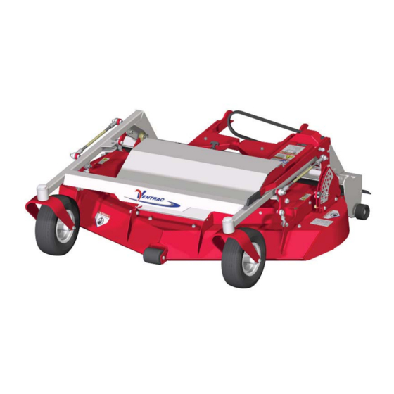
Product Description The MC600 mower is designed for the sole purpose of fi nish mowing. The MC600 features a 60 inch (152 cm) cutting width and sixteen cutting positions ranging from 3/4 inch (1.9 cm) to 4-1/2 inches (11.4 cm). -
Page 6: Using Your Manual
Manual Glossary Power Unit A Ventrac tractor or other Ventrac engine powered device that may be operated by itself or with an attachment or accessory. Attachment A piece of Ventrac equipment that requires a Power Unit for operation. -
Page 7: Safety
SAFETY Safety Decals The following safety decals must be maintained on your MC600 mower. Keep all safety decals legible. Remove all grease, dirt, and debris from safety decals and instructional labels. If any decals are faded, illegible, or missing, contact your dealer promptly for replacements. - Page 8 SAFETY Decal Description Part Number Quantity Danger, Shield Missing 00.0062 Warning, Moving Part Hazard 00.0101 Danger, Keep Hands & Feet Away 00.0123 Warning, Pinch Point 00.0218 Warning, Do Not Reach 00.0219 Warning, Read Owner’s Manual 00.0217 Warning, General Safety 00.0220 Danger, Thrown Object Hazard 00.0265 Safety - 8...
-
Page 9: General Safety Procedures
SAFETY General Safety Procedures for Ventrac Power Units, Attachments, & Accessories Training Required • The owner of this machine is solely responsible for properly training the operators. • The owner/operator is solely responsible for the operation of this machine and prevention of accidents or injuries occurring to him/her- self, other people, or property. -
Page 10: Preventing Accidents
SAFETY SAFETY General Safety Procedures for Ventrac Power Units, Attachments, & Accessories Operating Safely (continued) • If equipped with a high/low range feature, never shift between high and low range while on a slope. Always move the machine to level ground and place the selector lever in park before shifting range. -
Page 11: Operating On Slopes
SAFETY General Safety Procedures for Ventrac Power Units, Attachments, & Accessories Operating On Slopes • Slopes can cause loss-of-control and tip-over accidents, which can result in severe injury or death. Be familiar with the emergency parking brake, along with the power unit controls and their functions. -
Page 12: Maintenance
• If the power unit, attachment, or accessory requires repairs or adjustments not instructed in the opera- tor’s manual, the power unit, attachment, or accessory must be taken to an authorized Ventrac dealer for service. • Never perform maintenance on the power unit and/or attachment if someone is sitting in the operator’s seat. -
Page 13: Hydraulic Safety
SAFETY General Safety Procedures for Ventrac Power Units, Attachments, & Accessories Hydraulic Safety • Make sure all hydraulic connections are tight and all hydraulic hoses and tubes are in good condition. Repair any leaks and replace any damaged or deteriorated hoses or tubes before starting the machine. -
Page 14: Cutting Unit Safety
SAFETY MC600 Safety Procedures Cutting Unit Safety • Rotating Blades: Contact with the rotating mower blades or other moving parts may cause personal injury. Keep hands and feet away. • Rotation of one blade may cause another blade to rotate. -
Page 15: Operational Controls
Primary S.D.L.A. Control Lever*: Pull the lever to the left to raise the power unit front hitch and MC600 mower deck. Push the lever to the right to lower the power unit front hitch and mower deck. The control lever must be in the float (detent) The height adjustment handle (A) is used to raise or position during operation of the mower. -
Page 16: General Operation
Drive the power unit slowly forward into the hitch Transport of Mower arms of the MC600 mower. Align the lift arms of the power unit with the mower hitch arms by Transport the mower deck with the power unit front... -
Page 17: Cutting Height Adjustment
GENERAL OPERATION Cutting Height Adjustment Always set the parking brake, shut off the power unit engine, remove the ignition key, and ensure all moving parts have stopped before checking mower deck or blade condition, or attempting any repair or adjustment. Lift the height adjustment handle upward and slide the handle toward the front of the deck to engage the handle pin (A) into the notch in the... -
Page 18: Service
For best results, and to maintain the finish of the Place a short piece of 2 x 4 wood between the MC600, clean or wash the mower to remove accu- end of the blade and an appropriate structural mulated clippings, leaves, and dirt when the job is part of the underside of the deck to prevent the finished. -
Page 19: Detach The Mower Deck From The Power Unit
Engage the deck belt tensioning spring. sides of the deck when leveling is complete. Drive Belt Tensioning Adjustments Both drive belts of the MC600 mower are spring loaded to maintain proper belt tension. No adjust- ments are required. Tire Pressure Tire inflation should be maintained at 8-10 PSI. -
Page 20: Lubrication
Grease points are shown on a decal located on the under side of the deck shield. Storage Preparing the MC600 Mower for Storage 1. Clean the mower deck and frame. 2. Inspect for loose or missing hardware, damaged components, or signs of wear. -
Page 21: Mc600 Maintenance Schedule
SERVICE MC600 Maintenance Schedule MC600 Maintenance Checklist Service - 21... -
Page 22: Specifications
SPECIFICATIONS SPECIFICATIONS Dimensions Overall Height ....... 17-1/2 inches (44.5 cm) Overall Length . - Page 23 Blank Page...
-
Page 24: Parts
PARTS ILLUSTRATED DRAWING Deck, Pulleys, & Belt Serial # 1001-1151 Serial # 1001-1151 Use only original Ventrac Illustrated Parts - 24 replacement parts. - Page 25 27 ..60.1056 ....COVER, PULLEY (Serial # 1152-) ..........3 Use only original Ventrac Illustrated Parts - 25 replacement parts.
-
Page 26: Spindles & Blades
PARTS ILLUSTRATED DRAWING Spindles & Blades 87.0224 Use only original Ventrac Illustrated Parts - 26 replacement parts. - Page 27 16 ..87.0224-4 ....SHIELD, TOP ............. 1 * Included with 87.0224-1 spindle housing. Use only original Ventrac Illustrated Parts - 27...
-
Page 28: Hitch Arms
PARTS ILLUSTRATED DRAWING Hitch Arms Use only original Ventrac Illustrated Parts - 28 replacement parts. - Page 29 35 ..00.0219 ....DECAL, WARNING DO NOT REACH ......... . 1 Use only original Ventrac Illustrated Parts - 29 replacement parts.
-
Page 30: Carrier Frame, Wheels, & Front Roller
PARTS ILLUSTRATED DRAWING Carrier Frame, Wheels, & Front Roller 53.0133 53.0155 Use only original Ventrac Illustrated Parts - 30 replacement parts. - Page 31 48 ..29.GF0001 ....GREASE FTG, 1/4 SAE ST ..........1 Use only original Ventrac Illustrated Parts - 31 replacement parts.
-
Page 32: Deck Shields
PARTS ILLUSTRATED DRAWING Deck Shields Part of 47.0127 Use only original Ventrac Illustrated Parts - 32 replacement parts. - Page 33 17 ..05.0120 ....BUMPER, NEOPRENE 10 GA - 1/4 ..........2 Use only original Ventrac Illustrated Parts - 33 replacement parts.
-
Page 34: Rear Roller
PARTS ILLUSTRATED DRAWING Rear Roller Use only original Ventrac Illustrated Parts - 34 replacement parts. - Page 35 10 ..29.GF0001 ....GREASE FTG, 1/4 SAE ST ..........1 Use only original Ventrac Illustrated Parts - 35 replacement parts.
-
Page 36: Rear Belting
PARTS ILLUSTRATED DRAWING Rear Belting Use only original Ventrac Illustrated Parts - 36 replacement parts. - Page 37 8 ..99.SF04 ....NUT, SF 1/4-20 USS ............6 Use only original Ventrac Illustrated Parts - 37 replacement parts.
-
Page 38: Rear Crossbar
PARTS ILLUSTRATED DRAWING Rear Crossbar Use only original Ventrac Illustrated Parts - 38 replacement parts. - Page 39 16 ..03.0006 ....PIN, BALL 3/8 X 1” ............1 Use only original Ventrac Illustrated Parts - 39 replacement parts.
-
Page 40: Left Height Adjustment Linkage
PARTS ILLUSTRATED DRAWING Left Height Adjustment Linkage Use only original Ventrac Illustrated Parts - 40 replacement parts. - Page 41 19 ..95.06 ..... .WASHER, FLAT 3/8 SAE ........... . 2 Use only original Ventrac Illustrated Parts - 41 replacement parts.
-
Page 42: Right Height Adjustment Linkage
PARTS ILLUSTRATED DRAWING Right Height Adjustment Linkage Use only original Ventrac Illustrated Parts - 42 replacement parts. - Page 43 18 ..95.06 ..... .WASHER, FLAT 3/8 SAE ........... . 2 Use only original Ventrac Illustrated Parts - 43 replacement parts.
-
Page 44: Height Adjustment Handle
PARTS ILLUSTRATED DRAWING Height Adjustment Handle Use only original Ventrac Illustrated Parts - 44 replacement parts. - Page 45 8 ..99.SF0504 ....BOLT, SF 5/16-18 USS X 1/2 ..........1 Use only original Ventrac Illustrated Parts - 45 replacement parts.
-
Page 46: Mulch Kit #70.8088
PARTS ILLUSTRATED DRAWING Mulch Kit #70.8088 Use only original Ventrac Illustrated Parts - 46 replacement parts. - Page 47 5 ..99.SF0506 ....BOLT, SF 5/16-18 USS X 3/4 ..........12 Use only original Ventrac Illustrated Parts - 47 replacement parts.
-
Page 48: Warranty
Ventrac equipment. Proof of purchase may be required by the dealer to substantiate any warranty claim. - Page 49 (i) damage or defects due to or arising out of repair of Ventrac turf equipment by person or persons other than an authorized Ventrac service dealer or the installation of parts other than genuine Ventrac parts or Ventrac recommended parts.
Need help?
Do you have a question about the MC600 and is the answer not in the manual?
Questions and answers