Sign In
Upload
Download
Table of Contents
Contents
Add to my manuals
Delete from my manuals
Share
URL of this page:
HTML Link:
Bookmark this page
Add
Manual will be automatically added to "My Manuals"
Print this page
×
Bookmark added
×
Added to my manuals
Manuals
Brands
Ventrac Manuals
Lawn Mower
MY560
Operator's manual
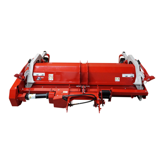
Ventrac MY560 Operator's Manual
Flail mower
Hide thumbs
1
2
Table Of Contents
3
4
5
6
7
8
9
10
11
12
13
14
15
16
17
18
19
20
21
22
23
24
25
26
27
28
29
30
31
page
of
31
Go
/
31
Contents
Table of Contents
Bookmarks
Table of Contents
Table of Contents
Introduction
Product Description
Why Do I Need an Operator's Manual
Using Your Manual
Manual Glossary
Safety
General Safety Procedures
Training Required
Requirements for Personal Protective Equipment (PPE)
Operation Safety
Keep Riders off
Operating on Slopes
Roadway Safety
Truck or Trailer Transport
Maintenance
Fuel Safety
Hydraulic Safety
Safety Decals
Operational Controls
Height Adjustment Handles
Primary SDLA Control Lever
Secondary SDLA Control Lever
Weight Transfer
General Operation
Daily Inspection
Attaching
Detaching
Checking for Rotor Vibration
Mowing and Operating Procedure
Transport of Attachment
Cutting Height Adjustment
Service
Cleaning and General Maintenance
Deck Flip up Procedure (Service Position)
Cutting Knife Inspection and Replacement
Belt Inspection
Attachment Drive Belt Replacement
Rotor Drive Belt Replacement
Rotor Drive Belt Tension Adjustment
Lubrication Locations
Checking the Gearbox Oil Level
Changing the Gearbox Oil
Storage
Maintenance Schedule
Maintenance Checklist
Specifications
Dimensions
Features
Noise Emissions - MY560
EC Declaration of Conformity - Ventrac MY560
Noise Emissions - MY720
EC Declaration of Conformity - Ventrac MY720
Warranty
Advertisement
Quick Links
Download this manual
Operator's Manual
MY560 / MY720
Flail Mower
Europe
VENTRAC.COM
Revised 06/07/21
Original Operator's Manual
09.10174 Rev. 01
Table of
Contents
Previous
Page
Next
Page
1
2
3
4
5
Advertisement
Table of Contents
Need help?
Do you have a question about the MY560 and is the answer not in the manual?
Ask a question
Questions and answers
Related Manuals for Ventrac MY560
Lawn Mower Ventrac MR740 Operator's Manual & Parts Drawings
Reel mower (41 pages)
Lawn Mower Ventrac MT720 Operator's Manual & Parts Drawings
Side discharge offset finish mower (49 pages)
Lawn Mower Ventrac MS600 Operator's Manual & Parts Drawings
Side discharge finish mower (49 pages)
Lawn Mower Ventrac MJ840 Operator's Manual & Parts Drawings
Contour mower (55 pages)
Lawn Mower Ventrac MJ840 Operator's Manual
Contour mower (30 pages)
Lawn Mower Ventrac MK960 Operator's Manual & Parts Drawings
Wide area mower (53 pages)
Lawn Mower Ventrac MY720 Operator's Manual
Flail mower (31 pages)
Lawn Mower Ventrac MC600 Operator's Manual & Parts Drawings
Rear discharge mower (49 pages)
Lawn Mower Ventrac Ventrac HQ680 Owner's/Operator's Manual
Tough-cut mower (30 pages)
Lawn Mower Ventrac LM600 Operator's Manual & Parts
(35 pages)
Lawn Mower Ventrac HP720 Owner/Operator's Manual & Parts List
(40 pages)
Lawn Mower Ventrac LM600 Operator Manual & Illustrated Parts List
(37 pages)
Lawn Mower Ventrac 4100 Series Owner's/Operator's Manual
(34 pages)
Lawn Mower Ventrac HM602 Operator's Manual & Parts Drawings
(39 pages)
Lawn Mower Ventrac LQ450 Operator Manual And Parts Drawings
Field mower (35 pages)
Lawn Mower Ventrac HQ680 Owner's And Operator's Manual
Tough-cut mower serial # 1001-1901 (33 pages)
This manual is also suitable for:
My720
39.55144
39.55145
Table of Contents
Print
Rename the bookmark
Delete bookmark?
Delete from my manuals?
Login
Sign In
OR
Sign in with Facebook
Sign in with Google
Upload manual
Upload from disk
Upload from URL


Need help?
Do you have a question about the MY560 and is the answer not in the manual?
Questions and answers