
Related Manuals for Ventrac HP720


Summary of Contents for Ventrac HP720
- Page 1 OWNER/OPERATOR’S MANUAL & PARTS LIST MOWER MODEL HM600/HM720/HP720 REVISED 06-26-06 Venture Products Inc. Orrville, OH 09.10013...
-
Page 2: To The Owner
TO THE OWNER Congratulations on the purchase of a new VENTRAC Mower! The purpose of this manual is to assist you in its safe and effective operation and maintenance. With proper usage and care, the Mower will provide many years of service. Please read and understand this manual entirely before using the Mower. -
Page 3: Table Of Contents
D-3 & 4 (HM600 Ser# AA1358--) (HM720 Ser# AA1189--) (HP720 Ser# AA1067--) ..Drive Belt Replacement ......D-4 Mower Tire Pressure. - Page 4 Figure 1 - Deck ........E-12 (HM600 Ser# AA1001-AA1262) ( HM720 Ser# AA1001-AA1134) (HP720 Ser# AA1001-AA1025) Figure 2 - Deck E-3 &...
-
Page 5: Introduction
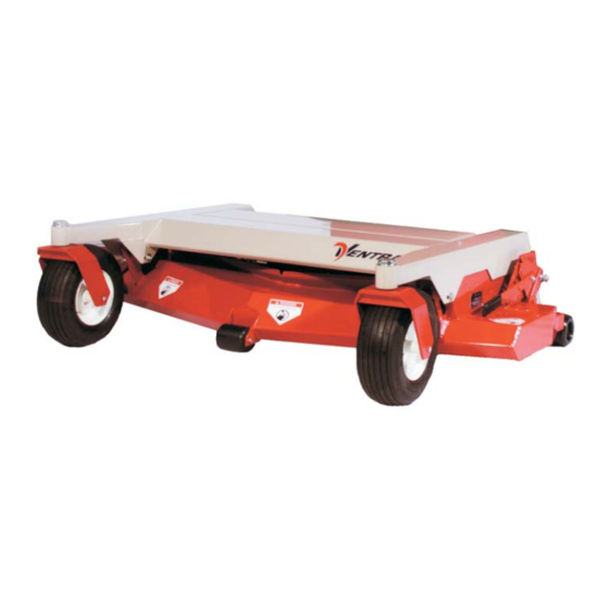
Careful, proper, and safe operation of tractor and mower will result in a great mowing job. The model HP720 provides a 6-1/2” offset of the mower to the left side. The mower still has a centered appearance because of the right side discharge chute. The offset creates a better “reach”... -
Page 6: Specifications
Weight ......435 pounds Ventrac HP720 Specifications Cutting Width ..... . Approx. 72 inches Overall Width . -
Page 7: Safety
SAFETY ATTENTION This symbol identifies potential health and safety hazards. It marks safety precautions. Your safety and the safety of others is involved. SIGNAL WORD DEFINITIONS Indicates an imminently hazardous situation which, if not avoided, will result in death or serious injury. This signal word is limited to the most extreme cases. -
Page 8: Decals
SAFETY Decals The following decals must be maintained on your Ventrac mower. If any decals are faded or missing, contact your dealer promptly for replacements. Page & Decal Description Part Number Location E-2,#37 Danger Shield Missing 00.0062 E-8,#15 Warning Moving Part Hazard 00.0101... -
Page 9: General Safety Procedures
SAFETY General Safety Procedures for Ventrac Tractors, Attachments, & Accessories Read and understand the operator’s manual before operating this equipment. Observe and follow all safety decals. DO NOT let children or any untrained person operate the tractor or attachment. Make sure that all operators of this equipment are thoroughly trained in using it safely. - Page 10 SAFETY HM600, HM720, and HP720 Safety Procedures Before making any repairs or adjustments, lower attachment to the ground, set parking brake, shut the engine off, and remove the key. Read and understand the operator’s manual before operating this equipment. Before mowing, clear the area of stones, sticks, and other foreign objects that can be thrown by the mower.
-
Page 11: Operation
OPERATION Operating Instructions Attaching: 1. Drive the tractor slowly forward into the hitch arms of the mower. Align the lift arms with the mower hitch arms by raising or lowering the front hitch and complete the engagement. Note: Mower arms may be too low to engage tractor hitch arms when mower cutting height is set in a low position. - Page 12 OPERATION Operating Techniques and Tips (cont.) Travel to and from the area to be mowed should generally be done with the mower raised in transport position by the tractor hydraulics. This saves the wear-and-tear on the mower and needless scuffing and rolling over the various surfaces between mowing jobs.
-
Page 13: Mulching Kit
OPERATION Mulching Kit The mulching kit consists of 3 baffles, a discharge cover and 10 carriage bolts and nuts. Kits are HM600—39.55150 and HM720—39.55151 . To install the mulching kit, simply turn the deck upside down or if mounted on the tractor (with park bake engaged and ignition key removed), tilt the deck to the servicing position and install the kit according to the drawing below. -
Page 14: Maintenance
MAINTENANCE Lubrication Grease zerks are located as shown below. Apply 2-3 pumps of grease per spindle approximately every 50 hours of operation. All others bearings—one pump max! Do not overgrease. In very dirty, sandy, or wet conditions, more frequent greasing may be advisable. -
Page 15: Deck Belt Replacement
Deck Belt Replacement: (HM600 Serial# AA1001-1357) (HM720 Serial# AA1001-1188) (HP720 Serial# AA1001-1066) If the deck belt is excessively worn or cracked, install a new belt. This is done most easily with the deck removed from the tractor. -
Page 16: Deck Belt Replacement
Deck Belt Replacement: (HM600 Serial# AA1358-) (HM720 Serial# AA1189-) (HP720 Serial# AA1067-) 1. Remove the rear lid of the deck. This is done by raising the lid and sliding it to the right to release hinge pin on the left side. -
Page 17: Drive Belt Replacement
MAINTENANCE Deck Belt Replacement (cont.): 3. Remove the left hitch arm mounting bolt and lift the hitch arm up from the mounting brackets on the deck. 4. Remove old belt. Note that one belt loop must surround the left hitch arm. This is the reason for removing the left hitch arm mounting bolt. -
Page 18: Storage
MAINTENANCE Deck Leveling Procedure (cont.): 3. Go to one side of the deck. Turn blade so that the tip is at the back of the deck. Measure the distance from the floor to the blade. 4. Move to the other side. Turn that blade tip to the back of the deck. If this measurement is different from the first, adjust the threaded rod linkage directly above on the top side of the deck until the measurement is the same as the first side. - Page 19 PARTS MANUAL HM600/HM720/HP720...
- Page 20 PARTS FIGURE 1 ILLUSTRATED DRAWING DECK PARTS (HM600 SER# AA1001-AA1262) (HM720 SER# AA1001-AA1134) (HP720 SER# AA1001-AA1025)
- Page 21 39 ....62.0859 ..Offset Deck, HP720 ... .
- Page 22 PARTS FIGURE 2 ILLUSTRATED DRAWING DECK PARTS (HM600 SER# AA1263-AA1945) (HM720 SER# AA1135-AA1612) (HP720 SER# AA1026-AA1180)
- Page 23 40 ....62.0900 ..Offset Deck, HP720 ... .
- Page 24 PARTS FIGURE 3 ILLUSTRATED DRAWING DECK PARTS (HM600 SER# AB1946--) (HM720 SER# AB1613--) (HP720 SER# AB1181--)
- Page 25 ....62.0900 ..Offset Deck, HP720 ... .
- Page 26 PARTS FIGURE 4 ILLUSTRATED DRAWING SPINDLE ASSEMBLY (HM600 SER# AB1946--) (HM720 SER# AB1613--) (HP720 SER# AB1181--)
-
Page 27: Spindle Assembly
PARTS FIGURE 4 SPINDLE ASSEMBLY HM600 HM720/HP720 REF. PART NO. PART NO. DESCRIPTION QTY. 1 ..81.B158 ..81.B180 ..Belt......1 2 . - Page 28 PARTS FIGURE 5 ILLUSTRATED DRAWING CARRIER FRAME PARTS (HM600 SER# AA1001-AA1262) (HM720 SER# AA1001-AA1134) (HP720 SER# AA1001-AA1025)
- Page 29 1 ....60.0758 ..Offset Deck Shield, HP720 ..
- Page 30 PARTS FIGURE 6 ILLUSTRATED DRAWING DECK PARTS (HM600 SER# AA1263--) (HM720 SER# AA1135--) (HP720 SER# AA1026) E-11...
- Page 31 1 ....60.0758 ..Offset Deck Shield, HP720 ..
- Page 32 PARTS FIGURE 7 ILLUSTRATED DRAWING CASTER & REAR ROLLER PARTS E-13...
- Page 33 PARTS FIGURE 7 CASTER & REAR ROLLER PARTS HM600 HM720/HP720 REF. PART NO. PART NO. DESCRIPTION QTY. 1 ..53.0080 ..53.0080 ..Dust Cap..... . 2 2 .
- Page 34 PARTS FIGURE 8 ILLUSTRATED DRAWING HITCH ASSEMBLY PARTS (HM600 SER# AA1001-AA1357) (HM720 SER# AA1001-AA1188) (HP720 SER# AA1001-AA1066) E-15...
- Page 35 PARTS FIGURE 8 HITCH ASSEMBLY PARTS HM600 HM720/HP720 REF. PART NO. PART NO. DESCRIPTION QTY. 1 ..99.E0004 ..99.E0004..1/4-20 Wing Nut ....1 2 .
- Page 36 PARTS FIGURE 9 ILLUSTRATED DRAWING HITCH ASSEMBLY PARTS (HM600 SER# AA1358--) (HM720 SER# AA1189--) (HP720 SER# AA1067--) E-17...
- Page 37 PARTS FIGURE 9 HITCH ASSEMBLY PARTS HM600 HM720/HP720 REF. PART NO. PART NO. DESCRIPTION QTY. 1 ..99.E0004 ..99.E0004..1/4-20 Wing Nut ....1 2 .
- Page 38 Ventrac equipment. Proof of purchase may be required by the dealer to substantiate any warranty claim. Only warranty work performed and submitted by an Authorized Ventrac Dealer may be eligible for warranty credit.
- Page 39 (i) damage or defects due to or arising out of repair of Ventrac turf equipment by person or persons other than an authorized Ventrac service dealer or the installation of parts other than genuine Ventrac parts or Ventrac recommended parts.
- Page 40 Ventrac Engine & Component Warranties VENDOR VENTRAC VENDOR WARRANTY PRODUCT WARRANTY PROCEDURE Kawasaki 3000 Series Two (2) years Claim processed by a Kawasaki authorized (Engines) 4200, 4100 Series servicing dealer to Kawasaki Vanguard 4200, 4100 Series Two (2) years Claim processed by a...
Need help?
Do you have a question about the HP720 and is the answer not in the manual?
Questions and answers