
Related Manuals for Ventrac HM600


Summary of Contents for Ventrac HM600
- Page 1 OWNER/OPERATOR’S MAN UAL & PARTS LIST MOWER MODEL HM600/HM720/HP720 RE VISED 02/05/20 Ven ture Prod ucts Inc. Orrville, OH 09.10013...
- Page 2 TO THE OWNER Congratulations on the purchase of a new VENTRAC Mower! The purpose of this manual is to assist you in its safe and effective operation and maintenance. With proper usage and care, the Mower will provide many years of service. Please read and understand this manual entirely before using the Mower.
-
Page 3: Table Of Contents
D-3 & 4 (HM600 Ser# AA1358--) (HM720 Ser# AA1189--) (HP720 Ser# AA1067--) ..Drive Belt Re place ment ......D-4 Mower Tire Pres sure. - Page 4 Fig ure 1 - Deck ........E-12 (HM600 Ser# AA1001-AA1262) ( HM720 Ser# AA1001-AA1134) (HP720 Ser# AA1001-AA1025) Fig ure 2 - Deck E-3 &...
-
Page 5: Introduction
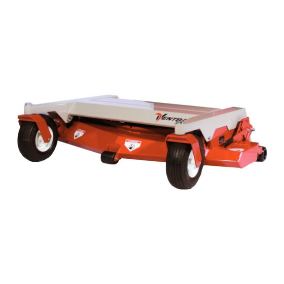
INTRODUCTION Prod uct De scrip tion The VENTRAC HM600, HM720 and HP720 mowers have a cutting width of approx. 60” and 72” respectively. The “uni-body” design creates a lightweight, heavy-duty, and high performance deck plus a streamlined carrier frame. With the removal of two pins beneath the cross frame, the deck can be tilted to a near vertical position for cleaning and servicing. - Page 6 INTRODUCTION Ventrac HM600 Spec i fi ca tions Cut ting Width ..... . Approx. 60 inches Over all Width ......70 inches Length .
- Page 7 SAFETY AT TEN TION This symbol identifies potential health and safety hazards. It marks safety precautions. Your safety and the safety of others is involved. SIG NAL WORD DEF I NI TIONS Indicates an imminently hazardous situation which, if not avoided, will result in death or serious injury.
-
Page 8: De Scrip Tion
SAFETY De cals The following decals must be maintained on your Ventrac mower. If any decals are faded or missing, contact your dealer promptly for replacements. Page & De cal De scrip tion Part Num ber Lo ca tion E-2,#37 Dan ger Shield Missing 00.0062... -
Page 9: Gen Eral Safety Pro Ce Dures
SAFETY Gen eral Safety Pro ce dures for Ventrac Trac tors, At tach ments, & Ac ces sories Read and understand the operator’s manual before operating this equipment. Observe and follow all safety decals. DO NOT let children or any untrained person operate the tractor or attachment. - Page 10 SAFETY HM600, HM720, and HP720 Safety Pro ce dures Before making any repairs or adjustments, lower attachment to the ground, set parking brake, shut the engine off, and remove the key. Read and understand the operator’s manual before operating this equipment.
-
Page 11: Op Er A Tion
OP ER A TION Op er ating In struc tions Attaching: 1. Drive the tractor slowly forward into the hitch arms of the mower. Align the lift arms with the mower hitch arms by raising or lowering the front hitch and complete the engagement. - Page 12 OPERATION Operating Techniques and Tips (cont.) Travel to and from the area to be mowed should generally be done with the mower raised in transport position by the tractor hydraulics. This saves the wear-and-tear on the mower and needless scuffing and rolling over the various surfaces between mowing jobs.
-
Page 13: Mulching Kit
The mulching kit consists of 3 baffles, a discharge cover and 10 carriage bolts and nuts. Kits are HM600—39.55150 and HM720—39.55151 . To install the mulching kit, simply turn the deck upside down or if mounted on the tractor (with park bake engaged and ignition key removed), tilt the deck to the servicing position and install the kit according to the drawing below. -
Page 14: Maintenance
MAINTENANCE Lubrication Grease zerks are located as shown below. Apply 2-3 pumps of grease per spindle approximately every 50 hours of operation. All others bearings—one pump max! Do not overgrease. In very dirty, sandy, or wet conditions, more frequent greasing may be advisable. -
Page 15: Deck Belt Re Place Ment
Deck Belt Re place ment: (HM600 Se rial# AA1001-1357) (HM720 Se rial# AA1001-1188) (HP720 Se rial# AA1001-1066) If the deck belt is excessively worn or cracked, install a new belt. This is done most easily with the deck removed from the tractor. -
Page 16: Deck Belt Re Place Ment
Deck Belt Re place ment: (HM600 Se rial# AA1358-) (HM720 Se rial# AA1189-) (HP720 Se rial# AA1067-) 1. Remove the rear lid of the deck. This is done by raising the lid and sliding it to the right to release hinge pin on the left side. -
Page 17: Drive Belt Re Place Ment
MAINTENANCE Deck Belt Re place ment (cont.): 3. Remove the left hitch arm mounting bolt and lift the hitch arm up from the mounting brackets on the deck. 4. Remove old belt. Note that one belt loop must surround the left hitch arm. This is the reason for removing the left hitch arm mounting bolt. -
Page 18: Fig Ure 3 - Deck
MAINTENANCE Deck Lev el ing Pro ce dure (cont.): 3. Go to one side of the deck. Turn blade so that the tip is at the back of the deck. Mea sure the dis tance from the floor to the blade. 4. - Page 19 PARTS MAN UAL HM600/HM720/HP720...
- Page 20 PARTS FIG URE 1 IL LUS TRATED DRAWING DECK PARTS (HM600 SER# AA1001-AA1262) (HM720 SER# AA1001-AA1134) (HP720 SER# AA1001-AA1025)
- Page 21 PARTS FIG URE 1 DECK PARTS HM600 HM720/HP720 REF. PART NO. PART NO. DE SCRIP TION QTY. 1 ..83.0031 ..83.0031 ..Idler Pul ley ..... 2 2 .
- Page 22 PARTS FIG URE 2 IL LUS TRATED DRAWING DECK PARTS (HM600 SER# AA1263-AA1945) (HM720 SER# AA1135-AA1612) (HP720 SER# AA1026-AA1180)
- Page 23 PARTS FIG URE 2 - DECK PARTS HM600 HM720/HP720 REF. PART NO. PART NO. DE SCRIP TION QTY. 1 ..83.0031 ..83.0031 ..Idler Pul ley ..... 2 2 .
-
Page 24: (Hm600 Ser# Ab1946--) (Hm720 Ser# Ab1613--) (Hp720 Ser# Ab1181--)
PARTS FIG URE 3 IL LUS TRATED DRAWING DECK PARTS (HM600 SER# AB1946--) (HM720 SER# AB1613--) (HP720 SER# AB1181--) - Page 25 PARTS FIG URE 3 DECK PARTS HM600 HM720/HP720 REF. PART NO. PART NO. DE SCRIP TION QTY. 1 ..83.0031 ..83.0031 ..Idler Pul ley ..... 2 2 .
-
Page 26: (Hm600 Ser# Ab1946--) (Hm720 Ser# Ab1613--) (Hp720 Ser# Ab1181--)
PARTS FIG URE 4 IL LUS TRATED DRAWING SPIN DLE ASSEMBLY (HM600 SER# AB1946--) (HM720 SER# AB1613--) (HP720 SER# AB1181--) - Page 27 PARTS FIG URE 4 SPIN DLE AS SEM BLY HM600 HM720/HP720 REF. PART NO. PART NO. DE SCRIP TION QTY. 1 ..81.B158 ..81.B180 ..Belt......1 2 .
- Page 28 PARTS FIG URE 5 IL LUS TRATED DRAWING CARRIER FRAME PARTS (HM600 SER# AA1001-AA1262) (HM720 SER# AA1001-AA1134) (HP720 SER# AA1001-AA1025)
- Page 29 2 ..00.0189 ..00.0189 ..Ventrac De cal ....
-
Page 30: (Hm600 Ser# Aa1263--) (Hm720 Ser# Aa1135--) (Hp720 Ser# Aa1026)
PARTS FIG URE 6 IL LUS TRATED DRAWING DECK PARTS (HM600 SER# AA1263--) (HM720 SER# AA1135--) (HP720 SER# AA1026) E-11... - Page 31 4 ..00.0139 ..00.0139 ..Ventrac De cal ....
- Page 32 PARTS FIG URE 7 IL LUS TRATED DRAWING CASTER & REAR ROLLER PARTS E-13...
- Page 33 PARTS FIG URE 7 CASTER & REAR ROLLER PARTS HM600 HM720/HP720 REF. PART NO. PART NO. DE SCRIP TION QTY. 1 ..53.0080 ..53.0080 ..Dust Cap..... . 2 2 .
-
Page 34: Fig Ure 9 - Hitch As Sem Bly
PARTS FIG URE 8 IL LUS TRATED DRAWING HITCH AS SEM BLY PARTS (HM600 SER# AA1001-AA1357) (HM720 SER# AA1001-AA1188) (HP720 SER# AA1001-AA1066) E-15... - Page 35 PARTS FIG URE 8 HITCH ASSEMBLY PARTS HM600 HM720/HP720 REF. PART NO. PART NO. DE SCRIP TION QTY. 1 ..99.E0004 ..99.E0004..1/4-20 Wing Nut ....1 2 .
-
Page 36: (Hm600 Ser# Aa1358--) (Hm720 Ser# Aa1189) (Hp720 Ser# Aa1067)
PARTS FIG URE 9 IL LUS TRATED DRAWING HITCH AS SEM BLY PARTS (HM600 SER# AA1358--) (HM720 SER# AA1189--) (HP720 SER# AA1067--) E-17... - Page 37 PARTS FIG URE 9 HITCH ASSEMBLY PARTS HM600 HM720/HP720 REF. PART NO. PART NO. DE SCRIP TION QTY. 1 ..99.E0004 ..99.E0004..1/4-20 Wing Nut ....1 2 .
Need help?
Do you have a question about the HM600 and is the answer not in the manual?
Questions and answers