
Subscribe to Our Youtube Channel
Related Manuals for Ventrac MJ840


Summary of Contents for Ventrac MJ840
- Page 1 Operator’s Manual MJ840 Contour Mower VENTRAC.COM Revised 07/29/22 Original Operator’s Manual 09.10055 Rev. 19...
- Page 2 To the Owner Contact Information and Product Identification If you need to contact an authorized Ventrac dealer for information on servicing your product, al- ways provide the product model and serial numbers. Please fill in the following information for future reference. See the picture(s) below to find the loca- tion of the identification numbers.
-
Page 3: Table Of Contents
TABLE OF CONTENTS INTRODUCTION PAGE 5 Product Description ..........5 Why Do I Need an Operator’s Manual? . - Page 4 TABLE OF CONTENTS SERVICE PAGE 20 Cleaning and General Maintenance ........20 Deck Flip Up Procedure .
-
Page 5: Introduction
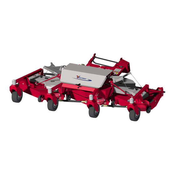
Product Description The MJ840 is designed for the sole purpose of finish mowing. The MJ840 features a 211 cm (83 inch) cutting width with full rear rollers for even cutting and striping, rear discharge, and a flip-up deck design. The MJ840 features three independently floating decks that follow the contour of the terrain with up to 40 degrees of mo- tion for each side deck. -
Page 6: Using Your Manual
Manual Glossary Power Unit A Ventrac tractor or other Ventrac engine powered device that may be operated by itself or with an attachment or accessory. Attachment A piece of Ventrac equipment that requires a Power Unit for operation. -
Page 7: Safety
SAFETY General Safety Procedures for Ventrac Power Units, Attachments, & Accessories Training Required • The owner of this machine is solely responsible for properly training the operators. • The owner/operator is solely responsible for the operation of this machine and for the prevention of ac- cidents or injuries occurring to him/herself, other people, or property. - Page 8 SAFETY General Safety Procedures for Ventrac Power Units, Attachments, & Accessories • Always wear a seat belt if the machine has a roll cage/bar installed and in the upright position. • Ensure the attachment or accessory is locked or fastened securely to the power unit before operating.
-
Page 9: Keep Riders Off
SAFETY General Safety Procedures for Ventrac Power Units, Attachments, & Accessories • Keep people and pets out of the working area. • Know the work area well before operation. Do not operate where traction or stability is questionable. • Reduce speed when you are operating over rough ground. -
Page 10: Roadway Safety
• If the power unit, attachment, or accessory requires repairs or adjustments not instructed in the operator’s manual, the power unit, attachment, or accessory must be taken to an authorized Ventrac dealer for service. • Never perform maintenance on the power unit and/or attachment if someone is in the operator’s station. -
Page 11: Fuel Safety
SAFETY General Safety Procedures for Ventrac Power Units, Attachments, & Accessories • Check the fuel lines for tightness and wear on a regular basis. Tighten or repair them as needed. • To reduce the hazard of fire, keep the battery compartment, engine, and muffler areas free of grass, leaves, and excess grease. -
Page 12: Hydraulic Safety
SAFETY General Safety Procedures for Ventrac Power Units, Attachments, & Accessories • If the fuel tank must be drained, it should be drained outdoors into an approved container. • Check the fuel lines for tightness and wear on a regular basis. Tighten or repair them as needed. -
Page 13: Cutting Unit Safety
SAFETY MJ840 Safety Procedures • The attachment hydraulic system may contain stored energy. Before performing maintenance or repairs on the hydraulic system, the attachment’s auxiliary hydraulic hoses must be disconnected from the power unit. Lower the attachment to the ground, shut off power unit engine, move the secondary SDLA lever left and right to relieve auxiliary hydraulic pressure, and disconnect the auxiliary hydraulic quick couplers. -
Page 14: Safety Decals
SAFETY Safety Decals The following safety decals must be maintained on your attachment. Keep all safety decals legible. Remove all grease, dirt, and debris from safety decals and instructional labels. If any decals are faded, illegible, or missing, contact your dealer promptly for replacements. When new components are installed, be sure that current safety decals are affixed to the replacement compo- nents. - Page 15 SAFETY Shield missing - do not operate. Fingers or hand entanglement. Pinching/crushing hazard. Stay away from moving parts. Fingers or hand entanglement. Keep all guards and shields in place. Warning - Read operator’s manual. Cutting/dismemberment hazard of hand or foot, mower blade. Stay away from moving parts.
-
Page 16: Operational Controls
OPERATIONAL CONTROLS Deck Pivot Latch Weight Transfer Terrain and ground conditions may affect the ap- propriate setting for the power unit’s weight transfer system. In most cases, the weight transfer system* should be set from 1/2 to 3/4 of the maximum capac- ity. -
Page 17: General Operation
GENERAL OPERATION Daily Inspection 6. Move the secondary SDLA lever side to side tor relieve any pressure in the auxiliary hoses. Discon- WARNING nect the hydraulic quick couplers from the power unit and store the hose ends on the attachment Always engage the parking brake, shut off the pow- where the couplers will be free of contamination. -
Page 18: Transport Of The Attachment
All the wheels and rear rollers must be set Anti-Scalp Roller Adjustment to the same cutting height position. The five anti-scalp rollers on the MJ840 have three 1. Flip the decks up to the service position. Refer to mounting positions. The correct mounting position is the Deck Flip Up Procedure in this manual. -
Page 19: Mulching Kit (Optional Accessory)
GENERAL OPERATION Mulching Kit (Optional Accessory) Mulching procedures may vary greatly due to the climate, the type of grass, and the soil conditions. It is generally best to mow frequently and in dry condi- tions. Leaves are usually mulched and dispersed bet- ter when some grass is cut with the leaves. -
Page 20: Service
If any component requires replacement, use only replaced. original Ventrac replacement parts. 3. Place a short piece of 2 x 4 wood between the end of the blade and an appropriate structural part of Cleaning and General Maintenance the deck frame to prevent the blade from rotating. -
Page 21: Belt Inspection
SERVICE Belt Inspection Center Deck Belt Replacement Inspecting the drive belts of the attachment can 1. Detach the mower deck from the power unit. prevent sudden belt failure by finding problems 2. Open the carrier frame cover. before they cause a belt to break. 3. -
Page 22: Right Deck Belt Replacement
3. Test the attachment to ensure that all the compo- hinge shield. nents are working properly. Drive Belt Tension Adjustments Each drive belt on the MJ840 mower is spring loaded to maintain proper belt tension. No adjustments are required. Service - 22... -
Page 23: Lubrication Locations
SERVICE Lubrication Locations Checking the Gearbox Oil Level Lubrication is required at the following locations using 1. Place the mower deck on a level surface. a lithium complex NLGI #2 grease. 2. Remove the plug (A) from either the rear or side of the gearbox to check the oil level. -
Page 24: Deck Leveling Procedure
SERVICE Deck Leveling Procedure 10. Turn the mower blades so the blade tips are at the rear of the deck and measure the distance be- Front to Rear Deck Leveling tween the flat surface and the blade tip. 1. Place the mower on a hard surface that is clean 11. - Page 25 SERVICE tip should be level to 3.2 mm (1/8 inch) lower at the front. 21. If the measurement at the front is higher or more than 3.2 mm (1/8 inch) lower, the deck must be leveled. To begin adjustments, loosen the four 3/8 inch bolts that fasten the front yoke anchor plate to the front of the right deck.
-
Page 26: Maintenance Schedule
SERVICE Maintenance Schedule Maintenance Schedule Grease and Lubrication: See Lubrication Section Jackshaft Bearing ü ü ü ü ü ü ü ü ü ü ü ü ü ü ü ü ü ü ü ü Hitch Arm Pivot ü ü ü ü ü... -
Page 27: Maintenance Checklist
SERVICE Maintenance Checklist Maintenance Checklist Grease and Lubrication: See Lubrication Section Jackshaft Bearing Hitch Arm Pivot Cylinder End Spindle Caster Wheel Pivot Yoke Pivot Rear Roller Bearing (Serial Number 1001-1875) Wheel Axle Bearing Gearbox Top Bearing Check Gearbox Oil Level Change Gearbox Oil. -
Page 28: Specifications
Three independent mower decks with 40 degrees of motion for the side decks. Front anti-scalp rollers Full length rear rollers Flat free front tires View all manuals Visit ventrac.com/manuals for the latest version of this operator’s manual. A downloadable parts manual is also available. Specifications - 28... -
Page 29: Warranty
V.P.I.; (f) repair or replacement arising as a result of any operation from Ventrac equipment that has been altered or modified so as to, in the determination of V.P.I., adversely affect the operation, performance or durability of the equipment or that has altered, modified or affected the equipment so as to change the intended use of the product;... - Page 30 (i) damage or defects due to or arising out of repair of the Ventrac equipment by a person or persons other than an authorized Ventrac service dealer or the installation of parts other than genuine Ventrac parts or Ventrac recommended parts.
Need help?
Do you have a question about the MJ840 and is the answer not in the manual?
Questions and answers