
Subscribe to Our Youtube Channel
Related Manuals for Ventrac MT720


Summary of Contents for Ventrac MT720
-
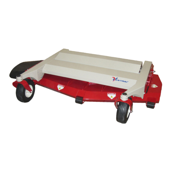
Page 1: Side Discharge
Operator’s Manual & Parts Drawings Side Discharge Offset Finish Mower Model MT720 Revised 11/15/17 Original Operator’s Manual 09.10140 Rev. 05... -
Page 2: To The Owner
To the Owner Contact Information and Product Identification If you need to contact an authorized Ventrac dealer for information on servicing your product, always provide the product model and serial numbers. Please fill in the following information for future reference. See the picture(s) below to find the location of the identification numbers. -
Page 3: Table Of Contents
TABLE OF CONTENTS INTRODUCTION PAGE 5 Product Description ..........................5 Why Do I Need an Operator’s Manual? ....................5 Using Your Manual ..........................6 Manual Glossary ............................6 SAFETY PAGE 7 Safety Decals ............................7 General Safety Procedures ........................9 Training Required ...........................9 Personal Protective Equipment Requirements ..................9 Operation Safety ............................9 Preventing Accidents ..........................10 Keep Riders Off ............................10... - Page 4 TABLE OF CONTENTS SERVICE PAGE 18 Cleaning and General Maintenance.....................18 Main Deck Cover Shield Removal and Installation ................18 Deck Flip-up Procedure (Service Position) ..................18 Mower Blade Inspection/Replacement ....................19 Mower Blade Sharpening ........................19 Belt Inspection ............................20 Drive Belt Replacement ........................20 Deck Belt Replacement ........................20 Deck Belt Tension Adjustment ......................21 Deck Leveling Procedure ........................21 Tire Pressure ............................22...
-
Page 5: Introduction
53.0148 Product Description The MT720 mower is designed for the sole purpose of finish mowing and is built to be the best cutting and longest lasting finish mower available. The high strength steel mower deck has an obstruction free grass chamber to minimize buildup and provide easy cleaning. -
Page 6: Using Your Manual
Manual Glossary Power Unit A Ventrac tractor or other Ventrac engine powered device that may be operated by itself or with an attachment or accessory. Attachment A piece of Ventrac equipment that requires a Power Unit for operation. -
Page 7: Safety
SAFETY Safety Decals The following safety decals must be maintained on your MT720 mower. Keep all safety decals legible. Remove all grease, dirt, and debris from safety decals and instructional labels. If any decals are faded, illegible, or missing, contact your dealer promptly for replacements. -
Page 8: Decal Description
SAFETY Decal Description Part Number Quantity Danger, Shield Missing 00.0062 Danger, Pinching Hazard 00.0102 Danger, Thrown Object Hazard 00.0122 Danger, Keep Hand & Feet Clear 00.0123 Warning, Moving Parts 00.0216 Warning, Read Owners Manual 00.0217 Warning, Do Not Reach 00.0219 Warning, General Safety 00.0220 Safety - 8... -
Page 9: General Safety Procedures
SAFETY General Safety Procedures for Ventrac Power Units, Attachments, & Accessories Training Required • The owner of this machine is solely responsible for properly training the operators. • The owner/operator is solely responsible for the operation of this machine and prevention of accidents or injuries occurring to him/her- self, other people, or property. -
Page 10: Preventing Accidents
SAFETY General Safety Procedures for Ventrac Power Units, Attachments, & Accessories Operation Safety (continued) • If equipped with a high/low range feature, never shift between high and low range while on a slope. Always move the machine to level ground and engage the parking brake before shifting range. -
Page 11: Operating On Slopes
SAFETY General Safety Procedures for Ventrac Power Units, Attachments, & Accessories Operating On Slopes • Slopes can cause loss-of-control and tip-over accidents, which can result in severe injury or death. Be familiar with the emergency parking brake, along with the power unit controls and their functions. -
Page 12: Maintenance
• If the power unit, attachment, or accessory requires repairs or adjustments not instructed in the operator’s manual, the power unit, attachment, or accessory must be taken to an authorized Ventrac dealer for service. • Never perform maintenance on the power unit and/or attachment if someone is in the operator’s station. -
Page 13: Hydraulic Safety
SAFETY General Safety Procedures for Ventrac Power Units, Attachments, & Accessories Fuel Safety (continued) • Do not overfill fuel tank. Only fill to bottom of fuel neck, do not fill fuel neck full. Overfilling of fuel tank could result in engine flooding, fuel leakage from the tank, and/or damage to the emissions control system. -
Page 14: Cutting Unit Safety
SAFETY MT720 Safety Procedures Cutting Unit Safety • Rotating Blades: Contact with the rotating mower blades or other moving parts may cause personal injury. Keep hands and feet away. • Rotation of one blade may cause another blade to rotate. -
Page 15: Operational Controls
Pull the power unit’s primary SDLA lever to the left of operational controls. The letter next to each control to raise the power unit front hitch and MT720 mower can be referenced to the list that follows these images. deck. Push the lever to the right to lower the power unit front hitch and mower deck. -
Page 16: General Operation
GENERAL OPERATION Daily Inspection Detaching 1. Park the power unit on a level surface and set the parking brake.* 2. Place the mower deck height adjustment handle Always set the parking brake, shut off power in position # 18. unit engine, remove the ignition key, and ensure 3. -
Page 17: Transport Of Mower
GENERAL OPERATION Transport of Mower Front Roller Position Always disengage the power unit PTO before trans- The three front rollers on the mower deck have porting the mower deck. an upper or lower mounting position. The correct mounting position is dependent on the selected Transport the mower deck with the power unit front cutting height. -
Page 18: Service
Manual Flip-up Procedure If any component requires replacement, use only 1. Park the power unit on a smooth level surface. original Ventrac replacement parts. 2. Engage the parking brake, shut off the engine, Cleaning and General Maintenance and remove the key from the ignition switch. -
Page 19: Mower Blade Inspection/Replacement
SERVICE 10. To return the deck to the operating position, 11. Reinstall the two Reinstall ball remove the two ball pins and rotate the deck to ball pins to lock pins to lock the operating position. deck in place the deck in the NOTE: if the front hitch lowers due to hydraulic upright position. -
Page 20: Belt Inspection
SERVICE Belt Inspection 5. Remove the left hitch arm mounting bolt and lift the hitch arm up away from the mounting brackets. Inspecting the drive belts of the mower can prevent sudden belt failure by finding problems before they cause a belt to break. Typical wear on a drive belt may... -
Page 21: Deck Belt Tension Adjustment
SERVICE Deck Belt Tension Adjustment Deck Leveling Procedure If the deck belt slips during normal mowing opera- CAUTION tion, the belt tension will need to be adjusted. 1. Park the power unit on a smooth level surface Mower blades may be sharp. Always wear heavy and lower the mower deck to the ground. -
Page 22: Tire Pressure
SERVICE 9. To adjust the front of the deck, loosen the cross 3. If the mower deck is equipped with a hydraulic bolts (B) in the carrier frame. flip-up kit, grease the flip-up rocker bracket. Move the bolts forward in the slots to lower the deck or move the bolts rearward in the slots to 4. -
Page 23: Storage
SERVICE Storage 7. Place the mower deck height adjustment handle into position # 18. Preparing the Mower for Storage 8. Clean and apply grease to the back side of 1. Clean the mower deck and frame. the rear carrier frame/mower deck slide plates 2. -
Page 24: Maintenance Schedule
SERVICE Maintenance Schedule Maintenance Schedule Grease & Lubrication: See Lubrication Section Caster Wheel Pivot Wheel Axle Bearing Rear Roller Bearing ... -
Page 25: Specifications
SPECIFICATIONS Dimensions Overall Height ....... 18-1/4 inches (46.4 cm) Overall Length ....... 66-1/8 inches (168 cm) Overall Width . -
Page 26: Parts
PARTS ILLUSTRATED DRAWING Main Frame, Discharge Chute & Baffle, Front Anti-Scalp Rollers Use only original Ventrac Illustrated Parts - 26 replacement parts. - Page 27 14 ..62.1462 ....FRAME, DECK WELDMENT MT720 ..
-
Page 28: Carrier Frame & Wheels
PARTS ILLUSTRATED DRAWING Carrier Frame & Wheels 53.0155 53.0148 Use only original Ventrac Illustrated Parts - 28 replacement parts. - Page 29 37 ..29.GF0001 ....GREASE FTG, 1/4 SAE ST ..........1 Use only original Ventrac Illustrated Parts - 29 replacement parts.
-
Page 30: Hitch Arms
PARTS ILLUSTRATED DRAWING Hitch Arms Use only original Ventrac Illustrated Parts - 30 replacement parts. - Page 31 18 ..62.1453 ....HITCH, ARM RIGHT MS720 ..........1 Use only original Ventrac Illustrated Parts - 31 replacement parts.
-
Page 32: Drive Shaft & Attachment Belt
PARTS ILLUSTRATED DRAWING Drive Shaft & Attachment Belt Use only original Ventrac Illustrated Parts - 32 replacement parts. - Page 33 15 ..90.0406 ....BOLT, 1/4-20 USS X 3/4” ........... . 1 Use only original Ventrac Illustrated Parts - 33 replacement parts.
-
Page 34: Main Deck Belt, Pulleys, & Belt Tensioner
PARTS ILLUSTRATED DRAWING Main Deck Belt, Pulleys, & Belt Tensioner Use only original Ventrac Illustrated Parts - 34 replacement parts. - Page 35 25 ..99.SF0508-8 ....BOLT, SRF 5/16-18 X 1 GR8 ..........3 Use only original Ventrac Illustrated Parts - 35 replacement parts.
-
Page 36: Spindles & Blades
PARTS ILLUSTRATED DRAWING Spindles & Blades 87.0241 Use only original Ventrac Illustrated Parts - 36 replacement parts. - Page 37 31 ..29.GF0017 ....FITTING, RELIEF ............1 Use only original Ventrac Illustrated Parts - 37 replacement parts.
-
Page 38: Rear Roller
PARTS ILLUSTRATED DRAWING Rear Roller Use only original Ventrac Illustrated Parts - 38 replacement parts. - Page 39 9 ..80.0388 ....ROLLER, REAR MS720 ........... . 1 Use only original Ventrac Illustrated Parts - 39 replacement parts.
-
Page 40: Height Adjust Linkage & Deck Slides
PARTS ILLUSTRATED DRAWING Height Adjust Linkage & Deck Slides Use only original Ventrac Illustrated Parts - 40 replacement parts. - Page 41 30 ..64.1180 ....TUBE, FRONT SLIDE............2 Use only original Ventrac Illustrated Parts - 41 replacement parts.
-
Page 42: Main Deck Cover Shield
PARTS ILLUSTRATED DRAWING Main Deck Cover Shield Use only original Ventrac Illustrated Parts - 42 replacement parts. - Page 43 18 ..60.1275 ....SHIELD, MAIN DECK COVER ..........1 Use only original Ventrac Illustrated Parts - 43 replacement parts.
-
Page 44: 70.8164 Mulch Kit
PARTS ILLUSTRATED DRAWING 70.8164 Mulch Kit Use only original Ventrac Illustrated Parts - 44 replacement parts. - Page 45 8 ..97.0506 ....BOLT, CARRIAGE 5/16 X 3/4 ..........7 Use only original Ventrac Illustrated Parts - 45 replacement parts.
-
Page 46: 70.8163 Hydraulic Flip Up Kit
PARTS ILLUSTRATED DRAWING 70.8163 Hydraulic Flip Up Kit 23.0168 Use only original Ventrac Illustrated Parts - 46 replacement parts. - Page 47 35 ..29.GF0001 ....GREASE FTG, 1/4 SAE ST ..........2 Use only original Ventrac Illustrated Parts - 47 replacement parts.
-
Page 48: Warranty
V.P.I. V.P.I.’s responsibility in respect to claims is limited to making the required repairs or replacements, and no claim of breach of warranty shall be cause for cancellation or rescission of the contract of sale of any Ventrac equipment. - Page 49 (ii) loss, cost, or expense relating to transportation or delivery of turf equipment from the location of owner or location where used by owner to or from any authorized Ventrac dealer; (iii) travel time, overtime, after hours time or other extraordinary repair charges or charge relating to repairs or replace- ments outside of normal business hours at the place of business of an authorized Ventrac dealer;...
Need help?
Do you have a question about the MT720 and is the answer not in the manual?
Questions and answers