
Related Manuals for Siargo MF4600


Summary of Contents for Siargo MF4600
- Page 1 Gas Mass Flow Meter VB.4 Model MF4600 Sold in North America by: Servoflo Corporation 75 Allen Street Lexington, MA 02472 www.servoflo.com/info@servoflo.com 781-862-9572...
- Page 2 User Manual Document No. 05‐2022‐CM1 EN Issue date: 2022.5 Revision: VB.4 Siargo Ltd. 3100 De La Cruz Boulevard, Suite 210 Santa Clara, CA 95054 USA Tel: +1(408)969.0368 Email: info@siargo.com © Copyright 2022 by Siargo Ltd. Siargo Ltd. and its subsidiaries reserve the right to change the specifications and/or descriptions without prior notice. For further information and updates, please visit: www.Siargo.com www.Siargo.com MF4600 User Manual 1 | P a g e ...
- Page 3 Only the trained or qualified personnel shall be allowed to perform product services. Use with caution! Be cautious for the electrical safety, even it operates at a low voltage, any electrical shock might lead to some unexpected damages. The gas to be measured should be clean and free of particles. Do not apply this meter for liquid medium. Do not apply for any unknown or non‐specified gases that may damage the product. For remote data, please be sure the meter is properly configured. www.Siargo.com MF4600 User Manual 2 | P a g e ...
-
Page 4: Table Of Contents
Detailed descriptions of the functions ................ 15 5.5 RS485 Modbus communication protocol ............... 17 5.5.1 Hardware connection .................... 17 5.5.2 Communication parameters .................. 1 8 5.5.3 Frame .......................... 1 8 5.5.4 Function codes ...................... 19 5.5.5 Registers ........................ 19 5.6 Analog output ..................... 22 5.6.1 4 ~ 20 mA output ...................... 22 5.6.2 0.5 ~ 4.5 Vdc output ...................... 23 5.7 Pressure loss ....................... 23 www.Siargo.com MF4600 User Manual 3 | P a g e ... - Page 5 8.2.4 Apply to a different gas medium .................. 29 Troubleshooting .................. 3 0 Warranty and Liability ................ 3 1 Service contact .................. 3 3 Appendix I: Product evaluation kit .............. 3 4 Appendix II: Document history ............... 3 5 www.Siargo.com MF4600 User Manual 4 | P a g e ...
-
Page 6: Overview
All contact information can be found at the end of this manual. This manual provides essential information for the operation of the MF4600 series of gas mass flow meters with a manual control valve for general‐purpose gas flow monitor and control applications. The product performance, maintenance, and trouble‐shooting as well as the information for product order, technical support, and repair are also included. MF4600 mass flow meters are designed for general purpose precise industrial gas processing monitor, or control. It can be used to replace the mechanical rotameters where digital data and/or remote control are required. The meter series cover a wide dynamic flow range with a working pressure rating of up to 1.0 MPa, and a temperature ranging from ‐10 to 55°C. The meters are operated with Siargo’s proprietary MEMS calorimetric mass flow sensors together with the smart control electronics. The sensor surface is passivated with silicon nitride ceramic ... -
Page 7: Receipt / Unpack Of The Products
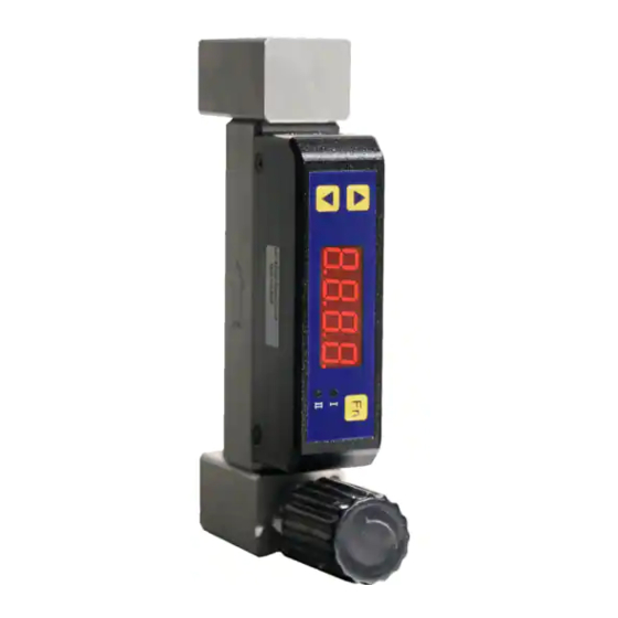
2. Receipt / unpack of the products Upon receipt of the products, please check the packing box before the dismantlement of the packing materials. Ensure no damages during shipping. If any abnormality is observed, please contact and notify the carrier who shipped the product and inform the distributors or sales representatives if the order is not placed directly with the manufacturer, otherwise, the manufacturer should be informed as well. For any further actions, please refer to the return and repair section in this manual. If the packing box is intact, proceed to open the packing box, and you shall find the product (either the meter or the meter with the valve per the actual order). The power adapter and/or data cable as shown below may also be found according to your actual order. Figure 2.1: MF4600 flow meter Figure 2.2: data cable Please check immediately for the integrity of the product as well as the power and data cable, if any abnormal is identified, please notify the distributor/sales representative or manufacturer as soon as you can. If any defects are confirmed, an exchange shall be arranged immediately via the original sales channel. (Note: the LED display shall not be lighted until the power cable is plugged in). This user manual shall also either be included in the packing box or via an online request for an electronic version. In most cases, this manual shall be made available to the customer before the actual order. The standard cable has an AMPMODU MTE (5 positions) compatible connector with a length of 0.5 meters. www.Siargo.com MF4600 User Manual 6 | P a g e ... -
Page 8: Knowing The Products
Table 3.1: MF4600 pin/wire assignments. Wire Color Definition 1 Blue RS485B 2 Green Analog output 4 ~ 20 mA /Analog output 0.5 ~ 4.5 Vdc 3 Red Power supply, 8 ~ 24 Vdc 4 Black Ground 5 Yellow RS485A The standard cable has an AMPMODU MTE (5 positions) compatible connector with a length of 0.5 meters. Figure 3.2: MF4600 connection and cable www.Siargo.com MF4600 User Manual 7 | P a g e ... -
Page 9: Mechanical Dimensions
1.0 88 138 90 BSPT 1/8” ~ 1/4” NPT 1/8” ~ 1/4” MF4602 2.0 73 ~ 80 134 94 BSPT 1/8” ~ 1/4” NPT 1/8” ~ 1/4” MF4603 3.0 73 ~ 80 134 94 BSPT 1/8” ~ 1/4” NPT 1/4” ~ 3/8” MF4608 8.0 73 ~ 80 138 90 BSPT 1/4” ~ 3/8” Note: * Other threads can be customized. For barbed connection, please use a converter. ** The range is from valve close to valve fully open. www.Siargo.com MF4600 User Manual 8 | P a g e ... -
Page 10: Installation
Please make sure the data cable meets industrial standards with proper shielding. g) Once the external power is successfully connected, the LED should be lighted up with the proper information displayed works correctly. h) Slowly open the valve(s) of the gas supply if any, upstream or downstream, or both of the pipeline. And then slowly open the valve of the meter, the meter should then start to measure the flow in the pipeline. Note: because the meter has a large dynamical measurement range, it could be normal if you see the small instant flow rate even if there is no flow in the pipeline. If www.Siargo.com MF4600 User Manual 9 | P a g e ... - Page 11 the value consistently present, double‐check the pipe leakage and then reset the offset if you are sure there is no leakage or flow. h) This will conclude the installation. Cautions a) Don't alter any parts of the product. b) Ensure the electrical connection is properly done per the instructions. c) Make sure no mechanical stresses in the connections. d) The strong electromagnetic interference sources close by or any mechanical shocks at the pipeline may also create malfunctioning of the product. e) Slowly open/close valves to prevent abrupt pulse flow impact. www.Siargo.com MF4600 User Manual 10 | P a g e ...
-
Page 12: Operation And Menu Description
Although this product complies with the CE‐required EMC regulations, it also requires the product to be used according to the standard electrical device practice. Before connecting the meter with external DC power or an AC‐DC adapter, make sure the supply voltage is within the range of the specified ones in Section 7. Be cautious that the standard electrical device precautions such as EDS (electrostatic discharge) and DC voltage are observed. Excessive electrostatic discharge may damage the product. The manufacturer‐supplied power and data cable have a locking fixture. Lock the cable and make sure it is properly engaging and will not be accidentally got unplugged. Half‐duplex RS485 Modbus is used for digital data communication. Make sure the wires are properly connected to the receiver side. www.Siargo.com MF4600 User Manual 11 | P a g e ... -
Page 13: Meter Display And Menu Descriptions
(a) When the instant flow rate is SLPM, the accumulated flow rate is registered with “standard liter” (SL), and the maximum can be 9,999,999.9 SL, or “normal cubic meters” (Nm ), and the maximum can be 999,999.99 Nm ; (b) When the instant flow rate is sccm, the accumulated flow rate is registered with “standard cubic centimeter” (scc), and the maximum can be 9,999,999.9 scc, or “standard liter” (SL), and the maximum can be 999,999.99 SL. The first four digits of the accumulated flow rate are indicated by the “I” LED light, and the last four digits are represented when the “II” LED light is on. The “I” and “II” LED lights will be automatically switched when the accumulated flow rate is displayed. The accumulated flow rate will be automatically saved every three minutes. At the time of the power failure or cut‐off, the value will be representing the latest saved ones. 5.4.2 MENU function input sequence At the flow measurement (main) display, press the three MEMU keys, it will allow the user to perform a variety of settings of the product. The following graph details the key sequence for each function, and some detailed explanations are followed after the graphic presentation. www.Siargo.com MF4600 User Manual 12 | P a g e ... - Page 14 Figure 5.2: MF4600 menu flow chart www.Siargo.com MF4600 User Manual 13 | P a g e ...
- Page 15 Set the upper flow rate alarm Available: 0 ~ 110, means of 0% ~ 110% full 6. 0 ~ 110 scale. The default value is 100 (100% full scale). Set the lower flow rate alarm Available: 0 ~ 110, means of 0% ~ 110% full 7. 0 ~ 110 scale. The default value is 0 (0% full scale). Set the display decimal. 8. 0 / 1 / 2 / 3 Available: 0 / 1 / 2 / 3, depends on the full scale. Set the communication baud rate 9. 48/ 96/192 Available: 48, 96, 192, 384, means of baud /384 rate 4800, 9600, 19200, 38400 bps. The default value is 384 (baud rate 38400). Set the GCF (gas conversion factor) Available: 10 ~ 999, means of GCF = 100 ~ A. 10 ~ 999 9990. Default value is 100, means of GCF = 1000. Set the accumulated flow rate unit. scc or SL (instant flow rate unit is sccm); b. 0 / 1 SL or Nm (instant flow rate unit is SLPM). Note: During this process, the meter will continue to measure the flow without being interrupted. www.Siargo.com MF4600 User Manual 14 | P a g e ...
-
Page 16: Detailed Descriptions Of The Functions
3) Set the Modbus address of the meter Use this function to set the RS485 Modbus address of the meter. This setting can also be done via the RS485 communication. 4) Set the response time Use this function to change the response time of the meter. The default one is 10 msec. Increasing the response time will allow more data to average and output a stabler flow rate if the actual flow rate may have some undesired fluctuation. Available response time is 10 msec (4. 1); 20 msec (4. 2); 50 msec (4. 5); 100 msec (4. 10); 200 msec (4. 20); 500 msec (4. 50), and 1000 msec (4.100) www.Siargo.com MF4600 User Manual 15 | P a g e ... - Page 17 Decimal options Default decimal 0 ~ 100, 200, 500 sccm 0, 1 0 0 ~ 1000, 2000, 5000 sccm 0 0 0 ~ 1, 2, 5 SLPM 0, 1, 2, 3 2 0 ~ 10, 20, 50 SLPM 0, 1, 2 1 9) Set the communication baud rate This function allows a MENU entry of the RS485 communication baud rate. 10) Set the GCF (the gas conversion factor) The meter is normally calibrated with air at 20°C and 101.325 kPa. When the user wants to set the standard conditions other than the specified temperature or applies the meter for other allowable gases (please contact the manufacturer for the list of gases), it is possible to use this gas conversion factor function to ensure the readings are correct and desired. www.Siargo.com MF4600 User Manual 16 | P a g e ...
-
Page 18: Rs485 Modbus Communication Protocol
When the instant flow rate unit is SLPM, the accumulated flow rate unit can be set to SL or Nm ; When the instant flow rate unit is sccm, the accumulated flow rate unit can be set to scc or SL. 5.5 RS485 Modbus communication protocol The digital communication protocol is based on standard Modbus RTU Half‐plex mode communication protocol. A master (PC or PLC) can communicate with multiple slaves (the current product) for data exchange and communication parameter configuration. Refer to Table 3.1 for cable connection. 5.5.1 Hardware connection The RS485 hardware layer is TIA/EIA‐485‐A, as illustrated below. In this configuration, the product (MF4600) is a slave. Figure 5.3: RS485 hardware www.Siargo.com MF4600 User Manual 17 | P a g e ... -
Page 19: Communication Parameters
Address Function codes Data CRC Stop_bits T1‐T2‐T3‐T4 8 bit 8 bit N 8 bit (20≥n≥0) 16 bit T1‐T2‐T3‐T4 Start_bits: 4 periods bit time, for a new frame. Address: The address can be set from 1 to 255 except for 157 (0x9d). 0 is the broadcast address. Function codes: Define the product (MF4600)'s functions/actions (slaves), either execution or response. Data: The address of the register, length of data, and the data themselves. CRC: CRC verification code. The low byte is followed by the high byte. For example, a 16 bit CRC is divided into BYTE_H and BYTE_L. In the framing, the BYTE_L will come first, then followed by the BYTE_H. The last one is the STOP signal. Stop_bits: 4 periods bit time, for ending the current frame. www.Siargo.com MF4600 User Manual 18 | P a g e ... -
Page 20: Function Codes
Baud rate Communication baud rate (R/W) 0x0015 40022 (0x0015) GCF* Gas conversion factor (R/W) 0x0016 40023 (0x0016) Response time* Response time or sampling time (R/W) 0x0017 40024 (0x0017) Reset offset* Reset or calibrate offset (R/W) 0x0027 40040 (0x0027) High flow alarm* Set high flow rate alarm (R/W) 0x0031 40050 (0x0031) Low flow alarm* Set low flow rate alarm (R/W) 0x0033 40052 (0x0033) Write protect Write protection of selected parameters (W) 0x0014 40021 (0x0014) Notes: 1, R – Read‐only, W – Write only, R/W – Read and write. 2, For the * marked functions, please disable the write protection before executing the command. www.Siargo.com MF4600 User Manual 19 | P a g e ... - Page 21 The unit should be identified as below: Unit Unit Model Flow rate (b.0) (b.1) MF4601/02/03 100/200/500/1000/2000/5000 sccm scc SL MF4602/03/08 1/2/5/10/20/50 SLPM SL Write Y 0x0015 Baud rate Read Y Description Communication baud rate Value type UINT 16 Value=0: 4800; 1: 9600; 2: 19200; 3: 38400. The default value is 3, the baud rate is 38400. Notes e.g.: When the user reads “3 (0x0003)” from register 0x0015, the baud rate is 38400. www.Siargo.com MF4600 User Manual 20 | P a g e ...
- Page 22 Write Y 0x0033 ~ 0x0034 Low flow alarm Read Y Description Set the low flow rate alarm limit Value type UINT 16 The low flow alarm value = [(0x0033)*65536+(0x0034)]/1000 Notes Notes: please disable the write protection before executing this command. Write Y 0x0027 Offset reset Read N Description Reset or calibrate the offset Value type UINT 16, fixed value 0xAA55 Send the fixed value 0xAA55 to register 0x0027. Notes Notes: 1.Please make sure there is no flow before executing this command. 2. Please disable the write protection before executing this command. www.Siargo.com MF4600 User Manual 21 | P a g e ...
-
Page 23: Analog Output
5.6 Analog output 5.6.1 4 ~ 20 mA analog output The loop resistor connection is illustrated below. The current output load depends on the power supply (the yellow area in the graph). The maximum load resistor, R , with a 24Vdc supply, will be 850 Ohm. Figure 5.4: 4 ~ 20 mA analog output. www.Siargo.com MF4600 User Manual 22 | P a g e ... -
Page 24: Pressure Loss
4.50 110 % F.S. 4.90 Figure 5.5: 0.5 ~ 4.5 Vdc analog output 120 % F.S. 4.90 5.7 Pressure loss The product is designed for low‐pressure loss. The major drop of the pressure is at the manual valve structure. The following graph illustrated the pressure losses of the selected models. Table 5.8: MF4602 pressure loss Flow rate Pressure loss (sccm) (Pa) 0.0 0 200.0 170 400.0 420 500.0 590 600.0 770 800.0 1220 1000.0 1750 Figure 5.6: MF4602 pressure loss www.Siargo.com MF4600 User Manual 23 | P a g e ... - Page 25 4.2 4.5 5.4 5.0 6.5 Figure 5.7: MF4603 pressure loss Table 5.10: MF4608 pressure loss Flow rate Pressure loss (SLPM) (kPa) 0.0 0 10.0 2.0 20.0 7.8 30.0 17.5 40.0 35.0 45.0 46.0 50.0 57.5 Figure 5.8: MF4608 pressure loss www.Siargo.com MF4600 User Manual 24 | P a g e ...
-
Page 26: Product Selection And Order Information
SLPM SCFH MF4601 1.0 0 ~ 100, 200 N1 ‐ NPT 1/8”‐female, N2 ‐ NPT 1/4”‐female, MF4602 2.0 0 ~ 500, 1000 0 ~ 1 0 ~ 1, 2 B1 ‐ BSPT 1/8”‐female, B2 ‐ BSPT 1/4”‐female MF4603 3.0 0 ~ 2000, 5000 0 ~ 2, 5 0 ~ 5, 10 N2 ‐ NPT 1/4”‐female, N3 ‐ NPT 3/8” ‐female, MF4608 8.0 0 ~ 10, 20, 50 0 ~ 20, 50, 100 B2 ‐ BSPT 1/4” ‐female, B3 ‐ BSPT 3/8” ‐female www.Siargo.com MF4600 User Manual 25 | P a g e ... -
Page 27: Order Contact And Customer Support
105.9 3.00 6.2 Order contact and customer support The sales offices and the sales distributors/representatives are listed at the end of this document. For small quantities, the order can be placed either through the Siargo website: www.siargo.com or the sales office. For large quantities, please contact the sales office, distributors, or sales representatives. Siargo is making every effort to ensure the quality of the products. In case of questions and/or product supports, please contact the customer service listed at the end of the document. www.Siargo.com MF4600 User Manual 26 | P a g e ... -
Page 28: Technical Specifications
‐20 ~ 70 °C Reference conditions 20°C, 101.325 kPa, air Fluid compatibility Non‐corrosive CE EN61326‐1; ‐2; ‐3 MF4601 MF4602 MF4603 MF4608 Maximum overflow 2 6 30 200 SLPM Maximum flow 0.3 1 4 30 SLPM/sec change Note: 1. For other features or specifications not listed, please contact the manufacturer. www.Siargo.com MF4600 User Manual 27 | P a g e ... -
Page 29: Technical Notes For The Product Performance
Another key point to compare the different flow meter is that as long as the fluidic flow is a continuous flow without pulsation, then the fluidic dynamic will have the system following the Bernoulli equation: where ρ is the fluid density; g is the acceleration due to gravity; P1 is the pressure of the reference meter; P2 is the pressure at the test meter; v1 is the velocity of the reference meter, and v2 is the velocity of the test meter. h1 and h2 are the corresponding height for the meters which in most cases www.Siargo.com MF4600 User Manual 28 | P a g e ... -
Page 30: Control Flow With A Manual Valve
Therefore, measurement by the meter for a gas medium other than the calibration gas would bear larger measurement errors, particularly at the low Reynold number range where the laminar flow has a sensitive flow profile. www.Siargo.com MF4600 User Manual 29 | P a g e ... -
Page 31: Troubleshooting
Connect the power, check the empty cable Cable connection incorrect Check cable No signal / display No flow or clogging Check flow and contamination Power regulator failure Return to factory Sensor failure Return to factory Large errors or unexpected Particles, fluid type Check system flow rate Erroneous or large noise Vibration, unstable flow Check system Valve not work Wire connection, valve Return to factory Offset unstable Circuitry instability Check system, power off No digital interface Wrong address, software Check commands, connection No wireless, BT cannot pair Wrong model, data jam Check model, power off/on www.Siargo.com MF4600 User Manual 30 | P a g e ... -
Page 32: Warranty And Liability
Siargo makes no warranty, representation, or guarantee and shall not assume any liability regarding the suitability of the products described in this manual for any purposes that are not specified in this manual. The users shall be held for full responsibility for validating the performance and suitability of the products for their particular design and applications. For any of the misusage of the products out of the scope described herein, the user shall indemnify and hold Siargo and its officers, employees, subsidiaries, affiliates, and sales channels harmless against all claims, costs, damages, and expense or reasonable attorney fee from direct or indirect sources. Siargo makes no other warranty, express or implied, and assumes no liability for any special or incidental damage or charges, including but not limited to any damages or charges due to installation, ... - Page 33 (2) Products that have been subject to chemical attacks, including exposure to corrosive substances or contaminants. In the case of battery usage, long term discharge or leakage induced damages; (3) Products that have been opened or dismantled for whatever reasons; (4) Products that have been subject to working conditions beyond the technical specification as described by this manual or related datasheet published by the manufacturer; (5) Any damages incurred by the incorrect usage of the products; (6) Siargo does not provide any warranty on finished goods manufactured by others. Only the original manufacturer's warranty applies; (7) Products that are re‐sold by unauthorized dealers or any third parties. www.Siargo.com MF4600 User Manual 32 | P a g e ...
-
Page 34: Service Contact
11. Service contact Siargo Ltd. is making every effort to ensure the quality of the products. In case of questions, and or product supports, please contact customer service at the address listed below. We will respond to your request in a timely fashion and will work with you toward your complete satisfaction. Customer service and all orders should be addressed to Siargo Ltd. 3100 De La Cruz Boulevard, Suite 210, Santa Clara, California 95054, USA Phone: +01(408)969‐0368 Email: info@Siargo.com For orders, please provide an accurate and full postal address. Siargo will not ship to P.O. Boxes or via a third party. For further information and updates, please visit www.Siargo.com. www.Siargo.com MF4600 User Manual 33 | P a g e ... -
Page 35: Appendix I: Product Evaluation Kit
The USB Cable to connect cable connected to the PC is also included. to the product For most of the products, the power from the PC via the USB cable will be sufficient to power the sensor product, no external power will be USB cable to required. However, for multiple sensors in serial, connect to PC the power via the USB cable may not be enough, an external power adapter with 8 ~ 24Vdc will External power be required. adapter (optional) www.Siargo.com MF4600 User Manual 34 | P a g e ... -
Page 36: Appendix Ii: Document History
Appendix II: Document history Revision B.4 (May 2022) Add the 4 ~ 20 mA output. Revision B.3 (November 2021) Corrections. Revision B.2 (June 2021) Corrections. Revision B.1 (March 2021) Reformat, corrections, add the evaluation kit. Revision A.5 (July 2019): Update the MENU key functions. Revision A.4 (July 2018): Add the RS485 Modbus protocol. Revision A.3 (November 2017): Added maximum overflow and maximum flow changes; Added the revision history (Appendix). www.Siargo.com MF4600 User Manual 35 | P a g e ...
Need help?
Do you have a question about the MF4600 and is the answer not in the manual?
Questions and answers