
Subscribe to Our Youtube Channel
Related Manuals for SystemAir Topvex 1000 R


Summary of Contents for SystemAir Topvex 1000 R
- Page 1 Topvex 1000, 1500, 2000 R Compact serie Operating and maintenance instructions Inbedrijfstelling en onderhoudsinstructies.
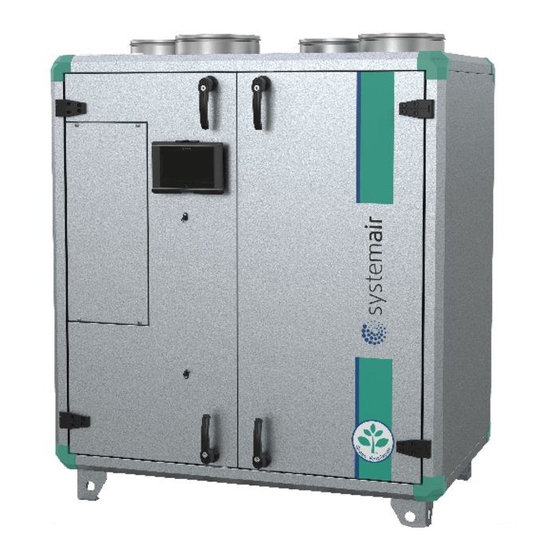
- Page 2 Left model / Links model Right model / Rechts model Fig. 1 Description Beschrijving Connection Supply air Aansluiting luchttoevoer Connection Extract air Aansluiting retourlucht Connection Exhaust air Aansluiting afblaas naar buiten Connection Fresh air Aansluiting verse buitenlucht Supply air filter (Topvex 1500, 2000) Luchttoevoerfilter (Topvex 1500, 2000) Supply air filter (Topvex 1000) Luchttoevoerfilter (Topvex 1000)
- Page 3 Fig. 2 Description Beschrijving Description Beschrijving Alarm button Alarm knop Connection block Aansluitstrip Alarm LED Alarm LED Yellow cable Gele draadl Write enable LED BevestigingsLED Orange cable Oranje draad OK button OK knop Red cable Rode draad Clearing button Reset knop Brown cable Bruine draad Mounting holes...
-
Page 4: Table Of Contents
Control unit, manual......................... 4 Warning ........................... 8 Maintenance ..........................8 Troubleshooting ........................9 Service ............................. 9 Commissioning record ......................10 NB. Systemair AB reserve the rights at any time, without prior notice, make changes and improvements to the contents of this manual. -
Page 5: Operation
Operation General Topvex unit with Electrical heater have 3 minutes of re-cooling after that it has been turned off. N.B. If activating the fire alarm when the heater is on the fan stops immediate without re-cooling, this can cause the overheating protection to trip. See page 3 Alarms –Overview how to reset. When changing a parameter in the control system it takes up to 1 minute for the change to be carried out. -
Page 6: Alarms
Alarms Alarm button (pos.1 in fig. 2) opens the alarm queue. Press this button and active and non-acknowledged alarms will be displayed in the menu window. The LED for alarms (pos.2 in fig. 2) is blinking if there are non-acknowledged alarms and steady if the alarms are still active but have been acknowledged. If there are multiple alarms use UP / DOWN buttons to move between them. -
Page 7: Control Unit, Manual
Control unit, manual Display shows Description Show if the unit is running in Manual or Automatic mode. Man / Auto: Show if the fans are running on Low, Medium or High speed or if the unit Fanspeed: is stopped. Activate extended running. Extended running is the time the unit goes Extended running from OFF (Low fan-speed or shut down mode) to ON (High, Medium or Low fan-speed). - Page 8 Description Display shows Reset filter alarm by setting the Reset alarm to Yes. Filter alarm Set the time until the filter alarm should be activated, 1-15 month. Set the status for Cooling to Active or Not Active. Preset is: Not Active. Functions Function: Controls a cold-water cooling battery with a 0-10 V DC signal.
- Page 9 Description Display shows Set the Air control mode to: • Supply. • Supply & Outdoor compensation. Set how much the control temp. should be compensated when the out door temperature is –20°C and +15°C (the compensation will be linear between these two points). E.g.
- Page 10 Description Display shows Show and Set the Analogue outputs. AO1: Heating battery, Electric or hot-water. Show the output signal, 0- 10V. Set the status to: Auto, Manual or Off. In Manual status it is possible to set the output signal within a range from 0 to10V, more than 2V activates the electrical re-heater (on/off function).
-
Page 11: Warning
The bag filter cannot be cleaned and must be changed as necessary. New filters can be ordered from Systemair. Operation time between filter changes must be re-set after filter change, see page 5 Filter alarm. To change the alarm activating time, see page 5 Filter alarm. -
Page 12: Troubleshooting
Troubleshooting Should problems occur, please check or correct the following before contacting your service representative. Always check if there are any alarms active in the control panel. 1. Fan(s) do not start Check that the fuses are not defect. Check the settings in the control panel (times, week schedule, auto, manual operating etc.). Check if there are any alarm messages. -
Page 13: Commissioning Record
Commissioning record Company Responsible Customer Date Installation Object / Unit Item no. Installation address Model / size Series no. Filter replaces interval set. Present time and date set. Week scheduler settings Preset On-time is: Period 1. 07:00-16:00 Monday-Sunday, Medium fan-speed. Period 2. - Page 14 Function Preset value Set value Temperature. Supply Supply outdoor Exhaust Supply Supply outdoor Exhaust Control function Temp. Control Temp. 18,0 °C °C Outdoor compensating Outdoor temp. Compensation: 20,0 °C °C -20,0 °C Compensation: 0,0 °C °C +15,0 °C Min. supply set point 12,0 °C °C Max.
- Page 15 Waarschuwing ........................24 Onderhoud ..........................24 Het oplossen van problemen ....................24 Service ........................... 24 Inbedrijfstellingrapport ......................24 Note. Systemair AB behoud zich het recht om op elk gewenst moment, zonder enige aankondiging, wijzigingen aan te brengen in dit document.
- Page 16 Inbedrijfstelling Algemeen De Topvex-unit met elektrische naverwarmer draait 3 minuten door nadat de unit is uitgeschakeld. N.B. wanneer het brandalarm is geactiveerd en de naverwarming is ingeschakeld, zal de ventilator direct stoppen met het afkoelen van de verwarmer. Dit omdat anders de oververhittingsbeveiliging zou kunnen beschadigen.
- Page 17 Alarm De Alarm toetsen (pos.1 in fig.2) openen de alarmregels. Druk op de toets en geactiveerde en niet bevestigde alarmeringen worden in de display weergegeven. De LED (pos.2 in fig.2) knippert wanneer er nog niet bevestigde alarmeringen zijn en brandt continu wanneer het alarm nog steeds actief is maar wel bevestigd.
- Page 18 Bedieningspaneel, handbediend Display-uitlezing Beschrijving Display geeft aan of de unit draait op handbediening of automatisch. Man / Auto: Display geeft aan of de ventilatoren op Laag, Midden of Hoge snelheid Ventilator.: draaien of dat de unit uit staat. Activeer verlengde draaitijd. Verlengde draaitijd is de tijd dat de unit Verlengde draaitijd vanuit UIT (Lage snelheid of uitgeschakelde positie) naar AAN (Hoog, Midden of Lage snelheid) UIT en AAN tijden en ventilatorsnelheden...
- Page 19 Beschrijving Display-uitlezing Bepaald hoeveel minuten (0-240) de unit vanuit UIT ( Lage snelheid of Verlengde draaitijd uitstand)naar AAN (Höog, Midden of hoge snelheid). AAN-tijden en ventilatorsnelheid zijn in te stellen via het submenu Weekprgramma. Het activeren van de verlengde draaitijd kan door middel van het drukken van de OK toets in het submenu Verlengde draaitijd..(gebruikers niveau) of door middel van een externe klok of drukknop.
- Page 20 Beschrijving Displayuitlezing Kies voor de temperatuurregeling op basis van;: • toevoerluchttemperatuur • toevoerluchttemperatuur met buitenluchttemperatuurcompensatie. Kies hoeveel de ingestelde temperatuur moet worden gecompenseerd wanneer de buitenluchttemperatuur –20°C resp. +15°C (de compensatie is lineair tussen deze twee punten.). B.v. bij –20 : 5°C. B.v.
- Page 21 Beschrijving Displayuitlezing b di Toont en kies de Analoge uitgangen. AO1: warmwater batterij, Elektrisch en warmwater. Toont het uitgangssignaal, 0-10V. Bepaalt de status in: Auto, Handbediend of uit. In de handbediende stand is het mogelijk om het uitgangssignaal in te stellen tussen 0 en 10V, meer dan 2V aktiveert de elektrische batterij (aan/uit funktie).
- Page 22 Het zakkenfilter kan niet worden gereinigd en dient te worden vervangen indien nodig. Nieuwe filters kunnen bij Systemair worden besteld. De tijd tussen twee filterwisselingen moet ingevoerd worden op het bedieningspaneel. Zie pagina 5 Filteralarm. Om de alarmtijd te veranderen zie ook pag 5 Filteralarm. De begindruk is ca 70 PA en de einddruk ca 220 Pa.
- Page 23 Het oplossen van problemen Ontstaan er problemen, controleer of corrigeer het volgende voordat u contact opneemt met het servicebedrij U dient eerst te controleren of er alarmmeldingen in het scherm worden weergegeven.. 1. Ventilator(en) draaien niet. Controleer alle zekeringen. Controleer alle instellingen in het bedieningspaneel(tijd, weekschema, auto, handbediening etc. ). Controleer of er alarmmeldingen zijn.
- Page 24 Inbedrijfstellingsrapport Bedrijfsnaam Verantwoordelijke Klant Datum Installateur. Unit/Kast Itemnummer Adres Type / grootte Serienr Filterinterval ingesteld op maanden Aktuele tijd & datum ingevoerd maand jaar Instellingen klok Ingestelde Aan tijd is: Periode 1. 07:00-16:00 Maandag-zondag, Middelste toerental. Periode 2. 00:00-00:00 Maandag-zondag. 00:00-00:00 schakelt naar UIT in de resterende periode. Voorinstelling UIT stand: Overige tijd: Lage ventilator snelheid.
- Page 25 Functie Fabrieksinstelling Ingestelde waarde Temperatur. Toevoer Toevoer & Toevoer Toevoer & Regelt op temp. buitenluchtcompensatie. Afvoerlucht buitenluchtcompensatie. Afvoerlucht Ingestelde temperatuur 18,0 °C °C Buitenlucht compensatie Buitentemp. Compensatie: 20,0 °C °C -20,0 °C Compensatie: 0,0 °C °C +15,0 °C Min. toevoer setpoint 12,0 °C °C Max.
- Page 26 Systemair AB Industrivägen 3 SE-739 30 Skinnskatteberg Phone +46 222 440 00 Fax +46 222 440 99 www.systemair.com 204264 22 September 2005...
Need help?
Do you have a question about the Topvex 1000 R and is the answer not in the manual?
Questions and answers