
Related Manuals for SystemAir Topvex SR 09, Topvex SR 11, Topvex TR 09


Summary of Contents for SystemAir Topvex SR 09, Topvex SR 11, Topvex TR 09
- Page 1 Topvex SR 09, 11, TR 09-15 Compact Air Handling Unit Installation instructions 207577-EN_GB Document in original language 04-04-2013 A003...
-
Page 2: Table Of Contents
Contents 1 Declaration of Conformity ......................1 2 Warnings........................... 2 3 Product information........................2 3.1 General ........................... 2 3.2 Technical data ........................3 3.2.1 Dimensions and weights Topvex SR 09, 11............... 3 3.2.2 Dimensions and weight Topvex TR 09-15 ..............4 3.2.3 Electrical data Topvex SR 09, 11, Topvex TR 09-15........... -
Page 3: Declaration Of Conformity
1 Declaration of Conformity Manufacturer Systemair AB Industrivägen 3 SE-739 30 Skinnskatteberg SWEDEN Office: +46 222 440 00 Fax: +46 222 440 99 www.systemair.com hereby confirms that the following products: Air handling units Topvex SR 09 EL Topvex SR 09... -
Page 4: Warnings
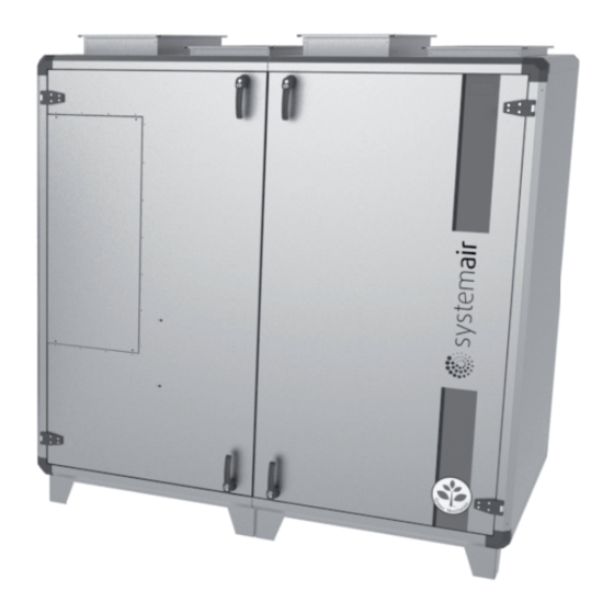
3.1 General This installation manual concerns air handling unit type Topvex SR 09, 11 and Topvex TR 09-15 manufactured by Systemair AB. The units include the following model options: • Model: SR 09, SR 11, TR 09, TR 12, TR 15 •... -
Page 5: Technical Data
3.2.1 Dimensions and weights Topvex SR 09, 11 15R (½") Fig. 1 Dimensions (mm) Model SR 09 1120 SR 11 1230 Model Weight, kg SR 09 SR 11 1025 Topvex SR 09, 11, TR 09-15 Installation instructions Systemair AB 207577... -
Page 6: Dimensions And Weight Topvex Tr 09-15
TR 09 1790 1630 1120 TR 12 1930 1740 1230 TR 15 1930 1980 1470 1180 Model Weight, kg TR 09 1030 TR 12 1140 TR 15 1000 1380 Topvex SR 09, 11, TR 09-15 Installation instructions Systemair AB 207577... -
Page 7: Electrical Data Topvex Sr 09, 11, Topvex Tr 09-15
4 Installation 4.1 Unpacking Verify that all ordered equipment are delivered before starting the installation. Any discrepancies from the ordered equipment must be reported to the supplier of Systemair products. Topvex SR 09, 11, TR 09-15 Installation instructions Systemair AB... -
Page 8: Where/How To Install
B. The two halves of the application are joined using 4 M10 screws, one in each corner C. It is possible dismount the gables by removing 6 MRX M6 screws with TH2 bits tool Reassemble in the reverse order. Fig. 3 Left hand version Topvex SR 09, 11, TR 09-15 Installation instructions Systemair AB 207577... -
Page 9: How To Split The Topvex Tr Unit
C. Remove the 7 M10 screws that join the two halves of the appliance Fig. 4 Left hand version 4.4 Installing the unit The unit must be installed in the following position (figure 5 and figure 6). Topvex SR 09, 11, TR 09-15 Installation instructions Systemair AB 207577... -
Page 10: Installation Procedure
Prepare the surface where the unit is to be mounted. Make sure that the surface is flat, levelled and that it supports the weight of the unit. Perform the installation in accordance with local rules and regulations. Topvex SR 09, 11, TR 09-15 Installation instructions Systemair AB 207577... - Page 11 • All electrical connections must be carried out by an authorized installer and in accordance with local rules and regulations. Topvex SR 09, 11, TR 09-15 Installation instructions Systemair AB 207577...
-
Page 12: Supply Air Sensor (Topvex Sr 09, 11)
The supply air sensor is enclosed in the unit package on delivery. Fig. 7 Installed supply air sensor (left hand connected unit) Topvex SR 09, 11, TR 09-15 Installation instructions Systemair AB 207577... -
Page 13: Installation Of Vav Models
The pressure transmitters need to be mounted in the supply and extract air ducts (figure 8) and connected according to table 2. Fig. 8 VAV installation Topvex SR 09, 11, TR 09-15 Installation instructions Systemair AB 207577... -
Page 14: Connections
Use insulating covering (minimum 100 mm mineral wool) with plastic diffusion barrier. In areas with extremely low outdoor temperatures during the winter, additional insulation must be installed. Total insulation thickness must be at least 150 mm. Topvex SR 09, 11, TR 09-15 Installation instructions Systemair AB 207577... - Page 15 To avoid noise being transferred between rooms via the duct system and also to reduce noise from the duct system itself, installation of silencers before every inlet diffuser is recommended. Topvex SR 09, 11, TR 09-15 Installation instructions Systemair AB 207577...
-
Page 16: Electric Connections
The figure shows the electrical connection box for the Topvex TR 09-15 units. The connection box for the Topvex SR 09, 11 has the same layout and components with the difference that the electrical heater is situated in a separate compartment. Topvex SR 09, 11, TR 09-15 Installation instructions Systemair AB 207577... - Page 17 (HW units only, not used in EL-units) Automatic fuse Automatic fuse for EL heater Contactor (K3) for control of EL heater Thermostat (EL units) Manual over heat protection reset (EL units) Topvex SR 09, 11, TR 09-15 Installation instructions Systemair AB 207577...
- Page 18 Modbus, Exo-line connection Exo-line E Exo-line connection LON + Option LON - Option Egnd LON Egnd Option DI 1 External alarm Normally open contact Use terminal 4 as reference Topvex SR 09, 11, TR 09-15 Installation instructions Systemair AB 207577...
- Page 19 Maximum current load for all DO combined: 8A Connection to external pressure sensor in case of pressure controlled unit (VAV) These inputs may only be wired to voltage free contacts Topvex SR 09, 11, TR 09-15 Installation instructions Systemair AB 207577...
- Page 20 RS-485 port and TCP/IP port can not be used simultaneously! I.e. possible communications are Modbus or exoline via RS-485 or Exoline (WEB) via TCP/IP. Fig. 12 BMS connection on the controller Topvex SR 09, 11, TR 09-15 Installation instructions Systemair AB 207577...
-
Page 21: Installing The Control Panel
Find an appropriate place to install the control panel. Maximum length between control panel and unit is 10 m as standard. If needed, drill two holes in the wall to hang the control panel (center to center: 60 mm) (pos.1, figure 14). Topvex SR 09, 11, TR 09-15 Installation instructions Systemair AB 207577... -
Page 22: Additional Equipment
For information concerning additional external equipment such as valve actuators, motorized dampers, E-tool, roof units, wall grilles etc. see technical catalogue and their enclosed instructions. For electrical connections of external components see enclosed wiring chart. Topvex SR 09, 11, TR 09-15 Installation instructions Systemair AB 207577... - Page 23 Topvex SR 09, 11, TR 09-15 Installation instructions Systemair AB 207577...
- Page 24 Systemair AB reserves the right to make changes and improvements to the contents of this manual without prior notice. Systemair AB Industrivägen 3 SE-739 30 Skinnskatteberg, Sweden Phone +46 222 440 00 Fax +46 222 440 99 www.systemair.com 207577...
Need help?
Do you have a question about the Topvex SR 09, Topvex SR 11, Topvex TR 09 and is the answer not in the manual?
Questions and answers