
Related Manuals for SystemAir Topvex SC Series


Summary of Contents for SystemAir Topvex SC Series
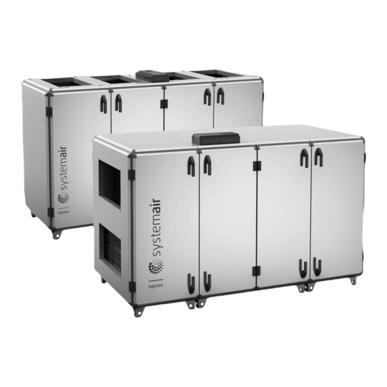
- Page 1 Air Handling Unit Topvex SC, TC Installation instructions Document in original language | 214958 · A001...
- Page 2 © Copyright Systemair AB All rights reserved E&OE Systemair AB reserves the rights to alter their products without notice. This also applies to products already ordered, as long as it does not affect the previously agreed specifications. 214958 | A001...
-
Page 3: Table Of Contents
Contents Product information .........1 12.2 Dimensions and weight Topvex TC ............. 32 Warnings............2 Unloading from trailer ........3 Lifting unit with forklift truck .....3 Using lifting frame ........4 Transport and storage ........5 Storage ..........5 Unpacking .............5 Duct connections..........6 Topvex SC..........6 Topvex TC..........7 Installation.............8 Requirements for installation ....9 Disassembly size SC 60-70, TC 60-... -
Page 5: Product Information
This manual includes the information required for installing the heat recovery unit type Topvex SC, TC manufactured by Systemair Sverige AB. The units include the following model options: The air handling units is delivered with airflow control CAV (Constant Air Volume). -
Page 6: Warnings
| Warnings Warnings The following admonitions will be presented in the different sections of the document: Danger • Indicates a potentially or imminently hazardous situation which, if not avoided, could result in death or serious injury. Warning • Indicates a potentially hazardous situation that may result in minor or moderate injuries. Caution •... -
Page 7: Unloading From Trailer
Unloading from trailer | Unloading from trailer Warning • The unit is heavy. Be careful during transport and installation. Risk of injury through pinching. Use protective clothing. • Observe the centre of gravity during transportation. The air handling unit is fixed on a pallet. Topvex SC60, Topvex SC70, Topvex TC60, Topvex TC70, are delivered fixed on pallet in sections and secured with a packing belt. -
Page 8: Using Lifting Frame
| Unloading from trailer Using lifting frame Warning • Secure the lifting cable on the tubes. • Do not compress the air handling unit’s chassi with the cables. Use a lifting frame connected to pipes in the air handling unit’s feet. For size Topvex SC20-Topvex SC35, Topvex TC20–Topvex TC35, place the lifting tubes in the outer feet of the air han- dling unit. -
Page 9: Transport And Storage
Transport and storage | Transport and storage Danger Do not loosen packing belt until the air handling unit is on location for installation! Storage Store the unit covered from dust, rain and snow. Keep duct connections covered during storage and installation. Unpacking Remove the plastic covering the air handling unit. -
Page 10: Duct Connections
| Duct connections Duct connections Topvex SC Supply air Extract air Exhaust air Outdoor air Description Position Fan supply air Fan extract air Filter supply air Filter extract air Heat exchanger Access control cabinet Damper by-pass outdoor air/Section defrosting (only units with section defrosting) Control box for section defrosting (only for unit with section defrosting) Internal electrical connection box Re-heater battery (EL or HWH/HWL) -
Page 11: Topvex Tc
Duct connections | Topvex TC Supply air Exhaust air Outdoor air Extract air Description Position Fan supply air Fan extract air Filter supply air Filter extract air Heat exchanger Access control cabinet Damper by-pass outdoor air/Section defrosting (only units with section defrosting) Control box for section defrosting (only for unit with section defrosting) Internal electrical connection box Re-heater battery (EL or HWH/HWL) -
Page 12: Installation
Verify that all ordered equipment are delivered before starting the installation. Report any deviation from the ordered equipment to the supplier of the Systemair products. On location for installation • Remove the screws in the pallet, loosen the packing belt. -
Page 13: Requirements For Installation
Installation | Requirements for installation Warning The unit is heavy. Be careful during transport and installation. Risk of injury through pinching. Use protective clothing. Location for installation • Level the floor surface. It’s important that the unit is completely in levelled before it is put into operation. •... -
Page 14: Disassembly Size Sc 60-70, Tc 60- 70
| Installation Disassembly size SC 60-70, TC 60-70 Disassemble the middle section for transport through smaller openings (min 900 mm). Heaviest part is the heat exchanger: 48kg x 2. Table 1 Tools required Allen key, 8 mm (5/16"), torx 20, screwdriver, drive pin punch Warning More than one person is needed to disassembly safely. - Page 15 Installation | Remove damper Warning Beware of sharp edges. Use gloves and protective clothing. 4. Loosen the bolts holding the damper rails. Remove the damper rails. 5. Rotate the damper and lift in the direction away from the exchanger. 6. Lift the damper out from the middle section. Caution Do not drag the damper on the exchanger.
- Page 16 | Installation Remove middle door beams 8. Loosen the screws on the door beams (6 screws on front and 6 screws on the back) and remove the beams. Remove the roof 9. Remove the cabling from the roof part. 10.Loosen and remove the 8 screws for the roof’s outer beams. 11.Remove the roof.
- Page 17 Installation | Remove the beams 13.Loosen and remove the 8 screws for the floor on the outer beams. 14.Loosen and remove the 8 screws on the reinforcement struts. 214958 | A001...
- Page 18 | Installation 15.Remove the beams. 16.Possible to disassembly the beams further. Remove the heat exchanger Caution • Handle the heat exchanger with care. • The heat exchanger is heavy. 17.Remove the heat exchanger and bypass. 214958 | A001...
-
Page 19: Assembly Of Topvex Sc60, Topvex Sc70
Installation | Assembly of Topvex SC60, Topvex SC70 Attach the heat exchanger Caution • Handle the heat exchanger with care. • The heat exchanger is heavy. 1. Carefully place the heat exchanger and bypass on the bottom plate. Fasten the beams 2. - Page 20 | Installation 3. Fasten the floor’s 8 screws on the outer beams. Fasten the roof Warning The roof part is bulky, two person is needed. 4. Fasten the roof’s outer beams with 8 screws. 5. Fasten the cabling to the roof. 214958 | A001...
- Page 21 Installation | Fasten the door beams 6. Fasten the door beams (6 screws on front and 6 screws on the back). Fasten the rail holding the partition wall 7. Fasten the bolts holding the rail on the opposite side of the partition wall. 214958 | A001...
- Page 22 | Installation Fasten the damper 8. Insert the damper in the area above the exchanger. Caution Do not drag the damper on the exchanger. 9. Lift the damper with the short end on the rail at the outer beams. Observe the small hooks to secure the damper. 10.Fasten the damper rails with the bolts.
- Page 23 Installation | 13.Unite the parts of the air handling unit using a pallet lift. 14.Open the middle doors and section doors. 15.Remove the filters for easy access. 16.Use an allen key on the side of the 8 connectors, to lock the unit’s sections. Fig.
- Page 24 | Installation 17.From the inside, attach the quick connection cables between the sides and middle section, figure 3. Cables are marked to facilitate correct connections. Note: Observe the cable markings. Fig. 3 Quick connection, image shows only one cable 214958 | A001...
-
Page 25: Connect The Condensation Drain
Installation | Connect the condensation drain Connect the drainage pipe and drain trap on the exhaust air side at the bottom of the unit figure 4. Cut the drainage pipe to required height, see table 2. Fig. 4 (mm) Table 2 H (mm) Max. -
Page 26: Mount The Supply Air Sensor
| Installation Mount the supply air sensor Mount the supply air sensor in the supply air duct. Connect the supply air sensor to the control unit CU27–C located in the Access control cabinet. Connect according to below table. All other temperature sensors are built in to the unit from factory. CU27 TG-KH/PT1000 Duct sensor T81: UI1... -
Page 27: Electrical Connections
Electrical connections | Electrical connections Danger • Disconnect the mains power supply to the unit before performing any maintenance or electrical work! • Carry out all electrical connections in accordance with local rules and regulation. Electrical connections must be carried out by an authorized installer. Warning The unit must not be put into operation before all the electrical safety precautions have been read and understood. -
Page 28: Connect Power Supply To Electrical Re-Heater
| Electrical connections Connect power supply to electrical re-heater Connect the mains power supply to the re-heater, figure 7. Possible to reset fuse and overheat protection for EL units without opening the hatch to the compartment. Fig. 7 Position Description Terminals for mains power supply Automatic fuse for heater Manual overheat protection reset... -
Page 29: Access Control Cabinet
Access control cabinet | Access control cabinet Danger Disconnect the mains power supply to the unit before moving the Access control cabinet or opening the lid. Warning Before obtaining access to terminals, all supply circuits must be disconnected. Access control cabinet is mounted on top of the unit. It is possible to remove the cabinet and mount it in a suitable loca- tion. -
Page 30: Cu27-C
| NaviPad control panel CU27–C All controlling through digital output is connected to CU27–C by using the cabling enclosed at delivery. Fig. 9 CU27–C NaviPad control panel NaviPad is not for outdoor mounting. The protection class of the NaviPad control panel is IP54 and permitted tempera- ture is 0-50°... -
Page 31: Connect Navipad
NaviPad control panel | 10.1 Connect NaviPad Loosen the 6 screws to the lid of Access control cabinet. Pull up the connection lid and the comb with plugs that seals the connection area. Brake loose one plug required to connect NaviPad. Connect NaviPad to the HMI inlet on CU27–C in the Access control cabinet. -
Page 32: Dimensions Navipad
| NaviPad control panel 10.3 Dimensions NaviPad NaviPad is the control panel for Systemair´s air handling units and contains several selectable languages. c/cD 40,3 59,4 77,5 10.4 Mount NaviPad holder on the air handling unit NaviPad control panel including 3 m cable, holder and screws are enclosed with the air handling unit. Mount the holder by using the holder as a drilling template. -
Page 33: User Levels
NaviPad control panel | 10.5 User levels Read /write — Home page (Figure 1) Possible actions in end user mode are to stop the air handling unit for End user maintenance (e.g. filter exchange), change the time for extended run and When logged out change the temperature setpoint. -
Page 34: Additional Equipment
| Additional equipment Additional equipment For information concerning additional external equipment such as valve actuators, motorized dampers, roof units, wall grilles etc. see technical catalogue and their enclosed instructions. For electrical connections of external components see enclosed wiring chart and separate documentation. Technical data 12.1 Dimensions and weight Topvex SC Dimensions are given in mm. - Page 35 Technical data | Topvex SC60, Topvex SC70 2742 1292 1015 1201 Model Topvex SC60 1074 Topvex SC70 1420 1017 1203 Table 3 Weight Topvex SC Model Weight, kg Topvex SC20 Topvex SC25 Topvex SC35 Topvex SC60 Topvex SC70 214958 | A001...
- Page 36 | Technical data 12.2 Dimensions and weight Topvex TC Topvex TC20 2000 ø313 Topvex TC25 2000 214958 | A001...
- Page 37 Technical data | Topvex TC35 2540 160 400 130 Topvex TC60, Topvex TC70 2742 1292 399 273 1015 1201 Topvex TC60 1074 Topvex TC70 1420 1017 1203 214958 | A001...
- Page 38 | Technical data Table 4 Weight Topvex TC Model Weight, kg Topvex TC20 Topvex TC25 Topvex TC35 Topvex TC60 Topvex TC70 214958 | A001...
- Page 39 Technical data | 214958 | A001...
- Page 40 Technical data | 214958 | A001...
- Page 41 Technical data | 214958 | A001...
- Page 42 Systemair Sverige AB Industrivägen 3 SE-739 30 Skinnskatteberg, Sweden Phone +46 222 440 00 www.systemair.com...
Need help?
Do you have a question about the Topvex SC Series and is the answer not in the manual?
Questions and answers