
Related Manuals for SystemAir Topvex SC03 EL


Summary of Contents for SystemAir Topvex SC03 EL
- Page 1 Topvex SC03-11 Compact Air Handling Unit Installation instructions 207575-EN_GB Document in original language 15-03-2016 A005...
-
Page 2: Table Of Contents
Contents 1 Declaration of Conformity ......................1 2 Warnings........................... 2 3 Product information........................2 3.1 General ........................... 2 3.2 Technical data ........................3 3.2.1 Dimensions and weights Topvex SC03-SC04............3 3.2.2 Dimensions and weight Topvex SC06............... 4 3.2.3 Dimensions and weight Topvex SC08-SC11 ............. 5 3.2.4 Electrical data ...................... -
Page 3: Declaration Of Conformity
SE-739 30 Skinnskatteberg SWEDEN Office: +46 222 440 00 Fax: +46 222 440 99 www.systemair.com hereby confirms that the following products: Air handling units Topvex SC03 EL Topvex SC04 HW Topvex SC08 Topvex SC03 Topvex SC06 EL Topvex SC08 HW... -
Page 4: Warnings
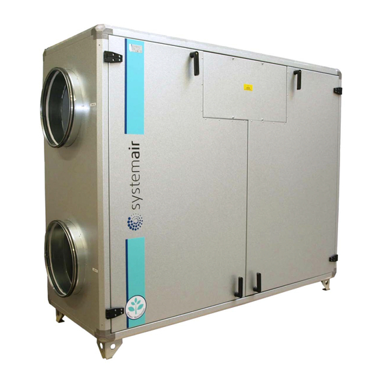
3 Product information 3.1 General This installation manual concerns air handling unit type Topvex SC03-11 manufactured by Systemair AB. Topvex SC03-11 include the following model options: • Model: SC03, SC04, SC06, SC08, SC11. • Heating coil: EL (Electric), HW (Water coil) or None. -
Page 5: Technical Data
3.2.1 Dimensions and weights Topvex SC03-SC04 Fig. 1 Dimensions (mm) SC03-SC04 (Drawn as left hand unit) Model SC03 1597 1531 SC04 1941 1531 Model Weight, kg 1463 SC03 1814 SC04 * male Topvex SC03-11 Installation instructions Systemair Sverige AB 207575... -
Page 6: Dimensions And Weight Topvex Sc06
3.2.2 Dimensions and weight Topvex SC06 Fig. 2 Dimensions (mm) SC06 (Drawn as left hand unit) Model SC06 2175 1622 Model Weight, kg SC06 * male Topvex SC03-11 Installation instructions Systemair Sverige AB 207575... -
Page 7: Dimensions And Weight Topvex Sc08-Sc11
3.2.3 Dimensions and weight Topvex SC08-SC11 Fig. 3 Dimensions (mm) SC08-SC11 (Drawn as left hand unit) Model SC08 2650 1771 1139 SC11 3211 1771 1552 Model Weight, kg SC08 1076 SC11 1492 * male Topvex SC03-11 Installation instructions Systemair Sverige AB 207575... -
Page 8: Electrical Data
Be careful so the unit don't tip over. 4 Installation 4.1 Unpacking Verify that all ordered equipment are delivered before starting the installation. Any discrepancies from the ordered equipment must be reported to the supplier of Systemair products. Topvex SC03-11 Installation instructions Systemair Sverige AB... -
Page 9: Where/How To Install
Connect the tubes for the pressure guard filter. Push the units together and fasten the assembly fitting (pos. 2) with a hex key. Make sure that there is enough space behind the unit to tighten the bolts. Fig. 4 Topvex SC03-11 Installation instructions Systemair Sverige AB 207575... - Page 10 Fig. 5 Topvex SC03-11 Installation instructions Systemair Sverige AB 207575...
-
Page 11: Condensation Drain
When installed in a non heated place the drain pipe and trap needs to be insulated well to prevent the water from freezing. Fig. 6 Drainage connection Fig. 7 Dimension and assembly Table 2: H (mm) Max. Negative pressure (Pa) 1000 Normal conditions Topvex SC03-11 Installation instructions Systemair Sverige AB 207575... -
Page 12: Installing The Unit
The unit must be installed in the following position. Fig. 8 Installation position (left hand unit) Fig. 9 Installation position (right hand unit) Table 3: Symbol description Symbol Description Supply air Exhaust air Outdoor air Extract air Topvex SC03-11 Installation instructions Systemair Sverige AB 207575... -
Page 13: Installation Procedure
• Make sure that the Mains supply to the unit is disconnected before performing any maintenance or electrical work! • All electrical connections must be carried out by an authorized installer and in accordance with local rules and regulations. Topvex SC03-11 Installation instructions Systemair Sverige AB 207575... -
Page 14: Supply Air Sensor
The pressure transmitters need to be mounted in the supply and extract air ducts (figure 11) and connected to terminals 40–42 (table 4). Fig. 11 VAV installation Topvex SC03-11 Installation instructions Systemair Sverige AB 207575... -
Page 15: Connections
Filter extract air Heat exchanger Electric compartment Damper bypass extract air Damper bypass outdoor air Pressure sensor extract air filer/extract air fan Pressure sensor supply air fan/supply air filter Pressure sensor defrosting exchanger Topvex SC03-11 Installation instructions Systemair Sverige AB 207575... - Page 16 To avoid noise being transferred between rooms via the duct system and also to reduce noise from the duct system itself, installation of silencers before every inlet diffuser is recommended. Topvex SC03-11 Installation instructions Systemair Sverige AB 207575...
-
Page 17: Electric Connections
• Make sure that the Mains supply to the unit is disconnected before performing any maintenance or electrical work! • All electrical connections must be carried out by an authorized installer and in accordance with local rules and regulations. Topvex SC03-11 Installation instructions Systemair Sverige AB 207575... - Page 18 Terminals for mains supply to the unit Contactor (K1) Contactor (K2) On/Off Pump control water (HW units only, not present in EL-units) Automatic fuse Automatic fuse for heater Contactor (K3) EL heater TTC El heater control Topvex SC03-11 Installation instructions Systemair Sverige AB 207575...
- Page 19 P:151/P2:61 connection P1:52/P2:62 Exo-line N Modbus, Exo-line connection DI 4 Extended running Normally open contact Use terminal 4 as reference DI 5 Fire alarm Normally open contact Use terminal 4 as reference Topvex SC03-11 Installation instructions Systemair Sverige AB 207575...
- Page 20 RS485(Modbus): 50-51-52 or 60-61-62 • RS485(BACnet): 50-51-52 or 60-61-62 • RS485(Exoline): 50-51-52-53 or 60-61-62-63 • TCP/IP Exoline • TCP/IP Modbus • TCP/IP WEB • TCP/IP BACnet Fig. 15 BMS connection on the controller Topvex SC03-11 Installation instructions Systemair Sverige AB 207575...
-
Page 21: Installing The Control Panel
A set of self-adhesive magnet strips are included in the package to facilitate installation on a metal surface. 4.8.3 Installation Find an appropriate place to install the control panel. Maximum length between control panel and unit is 100 m. Topvex SC03-11 Installation instructions Systemair Sverige AB 207575... -
Page 22: Additional Equipment
For information regarding additional external equipment such as valve actuators, motorized dampers, E-tool, wall grilles etc. see technical catalogue and their enclosed instructions For electrical connections of external components see enclosed wiring chart. Topvex SC03-11 Installation instructions Systemair Sverige AB 207575... - Page 23 Topvex SC03-11 Installation instructions Systemair Sverige AB 207575...
- Page 24 Systemair Sverige AB reserves the right to make changes and improvements to the contents of this manual without prior notice. Systemair Sverige AB Industrivägen 3 SE-739 30 Skinnskatteberg, Sweden Phone +46 222 440 00 Fax +46 222 440 99 www.systemair.com...
Need help?
Do you have a question about the Topvex SC03 EL and is the answer not in the manual?
Questions and answers