SystemAir Topvex TR03 Installation Instructions Manual
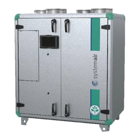
Compact air handling unit
Hide thumbs
Also See for Topvex TR03:
- Operation and maintenance instructions (17 pages) ,
- Installation description (16 pages) ,
- Operation and maintenance (32 pages)

Related Manuals for SystemAir Topvex TR03


Summary of Contents for SystemAir Topvex TR03
- Page 1 Topvex SR/TR03, SR/TR04, SR/TR06 Compact Air Handling Unit Installation instructions Document in original language | A003...
- Page 2 © Copyright Systemair AB All rights reserved E&OE Systemair AB reserves the rights to alter their products without notice. This also applies to products already ordered, as long as it does not affect the previously agreed specifications. 124454 | A003...
-
Page 3: Table Of Contents
Contents Declaration of Conformity .........1 Warnings............2 Product information .........2 General ..........2 Technical Data ........3 3.2.1 Dimensions and weights Topvex SR 03-06 .......3 3.2.2 Dimension and weights Topvex TR 03-06 .......5 3.2.3 Electrical data Topvex SR/TR 03-06........8 Transport and Storage ......9 Installation.............9 Unpacking ..........9 Where/how to install ......9... -
Page 5: Declaration Of Conformity
Topvex TR03-TR06 Topvex TR03-TR06 Topvex TR03-TR06 – Topvex TR03-TR06 M0 Topvex TR03-TR06 M0 Topvex TR03-TR06 M0 (The declaration applies only to product in the condition it was delivered in and installed in the facility in accordance with the included installation instructions. The insurance does not cover components that are added or actions carried out subsequently on the product) -
Page 6: Warnings
Product information General This installation manual concerns air handling unit type Topvex SR/TR 03-06 manufactured by Systemair AB. Topvex SR/TR 03-06 include the following model options: • M M o o d d e e l l : : SR03, SR04, SR06, TR03, TR04, TR06 •... -
Page 7: Technical Data
Product information | Technical Data 3.2.1 Dimensions and weights Topvex SR 03-06 Fig. 1 Dimensions (mm) SR03 (Drawn as a right hand unit) Fig. 2 Dimensions (mm) SR04, SR06 (Drawn as a right hand unit) D D ( ( c c / / c c ) ) E E ( ( c c / / c c ) ) M M o o d d e e l l SR04... - Page 8 | Product information 3.2.1.2 Space required Topvex SR 03-06 Fig. 3 Space required M M ( ( m m m m ) ) N N ( ( m m m m ) ) M M o o d d e e l l SR03 SR04 SR06...
-
Page 9: Dimension And Weights Topvex Tr 03-06
Product information | 3.2.2 Dimension and weights Topvex TR 03-06 Fig. 4 Dimensions (mm) TR03, TR04 (Drawn as a left hand unit) D D ( ( c c / / c c ) ) E E ( ( c c / / c c ) ) M M o o d d e e l l TR03 1180... - Page 10 | Product information Fig. 5 Dimensions (mm) TR06 Y: 15R 1/2″ Inner thread 3.2.2.1 Weights Topvex TR 03-06 (Drawn as a left hand unit) W W e e i i g g h h t t ( ( k k g g ) ) M M o o d d e e l l TR03 TR04...
- Page 11 Product information | 3.2.2.2 Space required Topvex TR 03-06 Fig. 6 Space required M M ( ( m m m m ) ) N N ( ( m m m m ) ) M M o o d d e e l l TR03 TR04 TR06...
-
Page 12: Electrical Data Topvex Sr/Tr 03-06
| Product information 3.2.3 Electrical data Topvex SR/TR 03-06 Table 1 Power Consumption E E l l H H e e a a t t i i n n g g F F u u s s e e ( ( m m a a i i n n s s ) ) ( ( A A ) ) f f o o r r F F a a n n s s ( ( W W t t o o t t . -
Page 13: Transport And Storage
Unpacking Verify that all ordered equipment are delivered before starting the installation. Any discrepancies from the ordered equipment must be reported to the supplier of Systemair products. Where/how to install Topvex SR/TR 03-06 are meant for indoor installation. Topvex SR03,SR04 and SR06 can be installed outside if weather protected. -
Page 14: Installing The Unit
| Installation Installing the Unit The unit must be installed in the following position (figure 8). Fig. 8 Installation position (left hand unit) Fig. 9 Installation position (right hand unit) Table 2 Symbol description S S y y m m b b o o l l D D e e s s c c r r i i p p t t i i o o n n Supply air Exhaust air... -
Page 15: Installation Procedure
Installation | 4.3.1 Installation procedure 1 1 Prepare the surface where the unit is to be mounted. Make sure that the surface is flat, levelled and that it sup- ports the weight of the unit. Perform the installation in accordance with local rules and regulations. 2 2 Lift the unit in place. - Page 16 | Installation Fig. 10 Installed supply air sensor (right hand connected unit) 124454 | A003...
-
Page 17: Connections
Installation | Connections 4.5.1 Ducting 4.5.1.1 Air connections principles Fig. 11 Connections and basic components in left hand connected units P P o o s s i i t t i i o o n n D D e e s s c c r r i i p p t t i i o o n n S S y y m m b b o o l l Connection supply air Connection exhaust air... - Page 18 | Installation 4.5.1.3 Silencers To avoid fan noise being transferred via the duct system, silencers should be installed both on supply and extract air. To avoid noise being transferred between rooms via the duct system and also to reduce noise from the duct system it- self, installation of silencers before every inlet diffuser is recommended.
-
Page 19: Electric Connections
Installation | 4.5.2 Electric Connections All electric connections are made in the electrical connection box which can be found in the front of the unit (figure 12). The hatch is removed by unscrewing four screws (figure 12). The unit must not be put into operation before all the electrical safety precautions have been read and understood. See the enclosed wiring diagram for internal and external wiring. - Page 20 | Installation 4.5.2.1 Electrical connection box, Components Topvex SR/TR 03-06 are equipped with a built in regulator and internal wiring (figure 13). The figure shows the electrical connection box for the Topvex TR 03-06 units. The connection box for the Topvex SR 03-06 has the same layout and components with the difference that the electrical heater is situated in a separate compartment.
- Page 21 Installation | Connections to external functions cont'd D D e e s s c c r r i i p p t t i i o o n n T T e e r r m m i i n n a a l l b b l l o o c c k k R R e e m m a a r r k k Used for phase 230V 1~ if the Phase (Main supply voltage)
- Page 22 | Installation 4.5.2.3 BMS Connection BMS Connection Communication possibilities for controller E283 WEB. • RS485(Modbus): 50-51-52 or 60-61-62 • RS485(Exoline): 50-51-52-53 or 60-61-62-63 • TCP/IP Exoline • TCP/IP Modbus • TCP/IP WEB • BACnet/IP Fig. 14 BMS connection on the controller 124454 | A003...
-
Page 23: Installing The Control Panel
Installation | Installing the Control Panel 4.6.1 Dimensions Fig. 15 Control panel dimensions D D i i m m e e n n s s i i o o n n s s ( ( m m m m ) ) P P o o s s i i t t i i o o n n 115.0 94.0... -
Page 24: Additional Equipment
| Installation Fig. 16 Control panel wire connections D D e e s s c c r r i i p p t t i i o o n n P P o o s s i i t t i i o o n n Mounting holes Connection block Connection to brown cable... - Page 25 124454 | A003...
- Page 28 Systemair Sverige AB Industrivägen 3 SE-739 30 Skinnskatteberg, Sweden Phone +46 222 440 00 Fax +46 222 440 99 www.systemair.com...
Need help?
Do you have a question about the Topvex TR03 and is the answer not in the manual?
Questions and answers