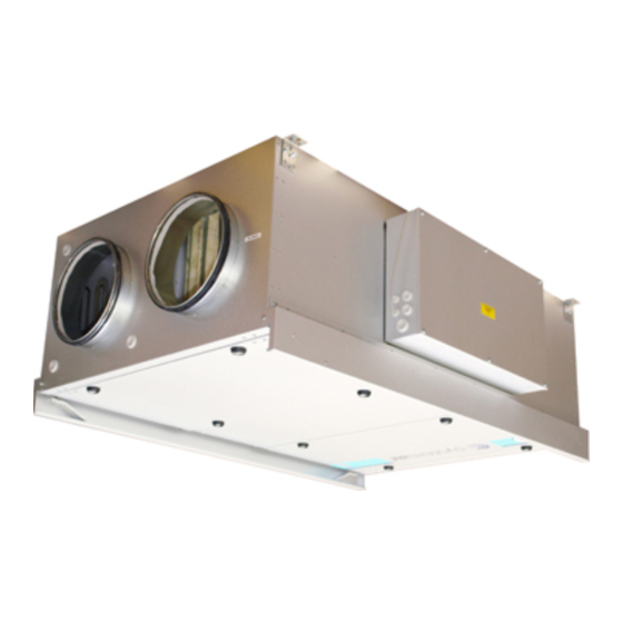
SystemAir Topvex FR03 Series Installation Instructions Manual

SystemAir Topvex FR03 Series Installation Instructions Manual

Air handling unit

Advertisement

Topvex FR03, FR06, FR08, FR11
Air Handling Unit
GB
Installation instructions
Document in original language | 151625 · A002

Advertisement

Table of Contents
loading
Need help?

Need help?

Do you have a question about the Topvex FR03 Series and is the answer not in the manual?

Questions and answers

Subscribe to Our Youtube Channel

Summary of Contents for SystemAir Topvex FR03 Series

  • Page 1 Topvex FR03, FR06, FR08, FR11 Air Handling Unit Installation instructions Document in original language | 151625 · A002...
  • Page 2 © Copyright Systemair AB All rights reserved E&OE Systemair AB reserves the rights to alter their products without notice. This also applies to products already ordered, as long as it does not affect the previously agreed specifications. 151625 | A002...
  • Page 3: Table Of Contents

    Contents EU Declaration of Conformity ......1 Warnings............2 Product information .........2 General ..........2 Technical data ........3 3.2.1 Dimensions .......3 3.2.2 Weights ........4 3.2.3 Space required......5 3.2.4 Electrical data ......5 Transport and storage ......6 Installation.............7 Unpacking ..........7 Where/how to install ......7 Installing the unit........8 Supply air sensor........
  • Page 5: Eu Declaration Of Conformity

    EU Declaration of Conformity | EU Declaration of Conformity Manufacturer Systemair Sverige AB Industrivägen 3 SE-739 30 Skinnskatteberg SWEDEN Office: +46 222 440 00 Fax: +46 222 440 99 www.systemair.com hereby confirms that the following products: Air handling units Topvex FR03 EL...
  • Page 6: Warnings

    Product information General This installation manual concerns air handling unit type Topvex FR manufactured by Systemair Sverige AB. Topvex FR include the following model options: • Model: FR03, FR06, FR08, FR11 • Heating coil: EL (Electric), HWL (Water coil, low power), HWH (Water coil, high power) or None.
  • Page 7: Technical Data

    Product information | Technical data 3.2.1 Dimensions Position Description Symbol Supply air Exhaust air Outdoor air Extract air Bottom side, left hand unit øD 1/2" Left hand unit Operating side, left hand unit 151625 | A002...
  • Page 8: Weights

    | Product information Description Symbol Position Supply air Exhaust air Outdoor air Extract air Bottom side, right hand unit øD Right hand unit Operating side, right hand unit Table 1 Dimensions Model FR03 1720 1115 ø315 1145 1502 FR06 2160 1315 ø400 1345...
  • Page 9: Space Required

    Product information | 3.2.3 Space required Fig. 1 Space required In case the sliding door application is installed the required space corresponds to the height of the sliding door support bars (50 mm). W (mm) Model FR03 FR06 FR08 FR11 3.2.4 Electrical data Table 2 Power Consumption...
  • Page 10: Transport And Storage

    | Product information Transport and storage The Topvex FR03–11 should be stored and transported in such a way that it is protected against physical damage that can harm panels, handles, display etc. It should be covered so that dust, rain and snow cannot enter and damage the unit and its components.
  • Page 11: Installation

    After completed installation the handles need to be removed to prevent unauthorized opening of the unit. Verify that all ordered equipment are delivered before starting the installation. Any discrepancies from the ordered equipment must be reported to the supplier of Systemair products. Fig. 4 Opening inspection hatches with a cap key Where/how to install The unit is meant for indoor installation.
  • Page 12: Installing The Unit

    | Installation Installing the unit The unit can be installed in the following positions Fig. 5 Possible installation positions Position Description Installation flat on the ground. Left and right connections are possible. Ceiling installation. Left and right connections are possible. Vertical wall installation with the supply air upward.
  • Page 13 Installation | 4 Install the unit by the use of the mounting brackets fit- ted on the unit on delivery. Note: If the unit is installed in the ceiling or on the wall assure that the unit is pressed tightly to the mounting surface before fastening the mounting brackets.
  • Page 14: Supply Air Sensor

    | Installation Supply air sensor The supply air sensor is enclosed in the unit package on delivery. Mount the supply air sensor the supply air duct 3 m after the air handling unit (figure 7). Connect the sensor to terminal 30–31 (chapter 4.6.6) in the electrical connection box.
  • Page 15 Installation | 4 Mount the wheels Mount the wheels in the prepared threaded inserts on the side of the inspection hatch with the enclosed screws and washers. 5 Sliding door support rails Mount the sliding door rails on each side of the unit. Fasten it to the casing with screws in the prepared threaded inserts.
  • Page 16 | Installation 7 Open hatch Open the hatch by unlocking the 2 inner handles (pos. 1) followed by the 2 outer handles (pos. 2). The hatch can now be pushed toward the centre of the unit. On- ly one hatch at the time can be opened like this. 8 Apply seal Apply the enclosed self adhesive seal strip to the in- ner frame of the unit casing.
  • Page 17: Connections

    Installation | Connections 4.6.1 Ducting Fig. 8 Air direction, left hand unit Fig. 9 Air direction, right hand unit Table 3 Symbols and descriptions Position Description Symbol Supply air Exhaust air Outdoor air Extract air Filter supply air Filter extract air Fan supply air Fan extract air Heat exchanger...
  • Page 18: Condensation And Heat Insulation

    | Installation 4.6.2 Condensation and heat insulation Outdoor air duct and exhaust ducts must always be well insulated against condensation. Correct insulation installation on ducts connected to the unit is especially important. All ducts installed in cold rooms/areas must be well insulated. Use insulating covering (minimum 100 mm mineral wool) with plastic diffusion barrier.
  • Page 19: Electrical Connections, Components

    Installation | 4.6.5 Electrical connections, components Topvex FR03–11 are equipped with a built in regulator and internal wiring (figure 11). Fig. 11 Electric components Pos 10 shows location of TTC in FR03 and FR06-FR11 Description Position Control unit CU283W-4 Transformer 230/24V AC Terminals for internal and external components Terminals for internal wiring Terminals for mains power supply to the unit...
  • Page 20: External Connections

    | Installation 4.6.6 External connections Table 4 Connections to external functions Terminal block Description Remark Ground Earthed neutral (mains power supply) Used for phase 230V 1~ and 400V 3~ Used for phase 230V 1~ if the Phase (mains power supply) unit has this mains 400V 3~/230V 3~ Phase (mains power supply)
  • Page 21: Bms Connection

    Installation | 4.6.7 BMS Connection Communication possibilities for control unit. • RS485(Modbus): 50-51-52 or 60-61-62 • RS485(BACnet): 50-51-52 or 60-61-62 • RS485(Exoline): 50-51-52-53 or 60-61-62-63 • TCP/IP Exoline • TCP/IP Modbus • TCP/IP WEB • TCP/IP BACnet RS 485 connection Fig.
  • Page 22: Installing Navipad Control Panel

    100 meters of cable. 4.7.1 Dimensions NaviPad is the control panel for Systemair´s Air handling units. NaviPad has an easy to understand menu structure and contains 13 languages. c/cD 40,3...
  • Page 23: Mounting Control Panel

    Installation | 4.7.2 Mounting control panel The NaviPad control panel with 3 m cable and holder are enclosed with the air handling unit. Self drilling screws are en- closed at delivery for mounting of the panel holder on the air handling. For mounting to a wall use suitable fastenings screws depending on the surface.
  • Page 24 Systemair Sverige AB Industrivägen 3 SE-739 30 Skinnskatteberg, Sweden Phone +46 222 440 00 Fax +46 222 440 99 www.systemair.com...

Table of Contents