Table of Contents
Advertisement
Quick Links
Advertisement
Table of Contents

Related Manuals for Datalogic T4 Series


Summary of Contents for Datalogic T4 Series
- Page 1 T4x-Series QuickStart Guide Publication # 821002560...
- Page 2 T4x-Series™ Reference Manual Edited: 07/2013 © 2013 Datalogic Automation, Inc. ALL RIGHTS RESERVED. Protected to the fullest extent under U.S. and international laws. Copying or altering of this document is prohibited without express written consent from Datalogic Automation, Inc. (DLA) Datalogic and the Datalogic logo are registered trademarks of Datalogic S.p.A.
-
Page 3: Reference Documentation
CD. SERVICE AND SUPPORT DLA provides several services as well as technical support through its website. Log on to www.datalogic.com and click on one of the following links for further information: • PRODUCTS Search through the links to arrive at your product page which describes specific Info, Features, Applications, Models, Accessories, and specific Downloads. -
Page 4: Emc Compliance
COMPLIANCE COMPLIANCE For installation, use, and maintenance, it is not necessary to open the camera. Opening the camera will void the warranty. Connect Ethernet and dataport connections to a network which has routing only within the plant or building and no routing outside the plant or building. EMC COMPLIANCE In order to meet the EMC requirements: •... -
Page 5: General View
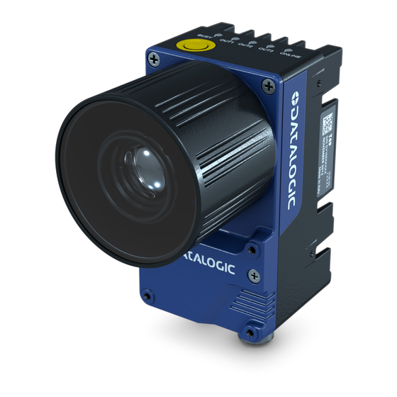
GENERAL VIEW GENERAL VIEW T4x-Series™ Camera Power Indicator LED Power, Serial Interface, and I/O Connector MAC Address label Ethernet Connector Ethernet Network Presence LED Not Used – No Connection Indicator Lights (see page Error! Bookmark not defined.) Reset and Camera Button Event (see page 8) Configuration ASSEMBLE THE CAMERA The first step to perform is to assemble any accessories that make up the T4x-Series™... - Page 6 T4x-SERIES QUICKSTART GUIDE Remove the sensor protection label (dust cap) by pulling it off of the base. Mount a lens by slowly screwing it onto the base until it arrives at the mechanical stop. Anti-vibration components (optional) Protective Film on front of cover (remove before calibration) Lens Cover Lens...
- Page 7 CONNECT THE SYSTEM • Power Supply Connection Use the PG-120 power Kit (3 versions for European, UK or US plug) and CAB-PG-0002 + BA400 connector to connect the PG-120 to the CBX. An alternative power supply to the PG- 120 is the PWR-120. CBX Connection •...
-
Page 8: Indicators And Keypad Button
T4x-SERIES QUICKSTART GUIDE INDICATORS AND KEYPAD BUTTON Figure 2 - Indicators The following LED indicators are located on the camera (Figure 2): On – camera is connected to power POWER On – Ethernet link is established. Blinking - data transmission On –... -
Page 9: Mechanical Dimensions
MECHANICAL DIMENSIONS MECHANICAL DIMENSIONS The T4x-Series can be installed to operate in different positions using the body mounting bracket shown in Figure 3. Use the fourteen screw holes (M4) on the body of the camera for custom mounting solutions. The diagrams on this page give the overall camera dimensions. -
Page 10: Mounting The Camera
T4x-SERIES QUICKSTART GUIDE MOUNTING THE CAMERA Using the T4x-Series mounting brackets, you can obtain rotation on the various axes of the camera as shown in the diagrams below. Figure 3 –Positioning with Body Mounting Bracket (Back) CBX ELECTRICAL CONNECTIONS All T4x-Series cameras can be connected to a CBX500 connection box using a CAB-SCSxx accessory cable. -
Page 11: Power Supply
POWER SUPPLY Outputs Power Source - Outputs Power Reference - Outputs Output 1 + Output 1 - Output 2 + Output 2 - Strobe + / Output 3 + (See Note) Strobe - / Output 3 - RS232 Interface Transmit Receive SGND Signal Ground (See Caution) -
Page 12: Rs-232 Serial Interface
T4x-SERIES QUICKSTART GUIDE RS232 SERIAL INTERFACE The signals relative to the following serial interface types are available on the CBX spring clamp terminal blocks. The serial interface parameters (baud rate, data bits, etc.) are defined in Vision Program Manager (VPM) software. Refer to the Serial Port section of the Impact Reference Guide (Publication # 843-0093). -
Page 13: External Trigger Connections
INPUTS Debounce Filter. Refer to the Camera Setup tab section in the Impact Reference Guide for further details. These inputs are optocoupled and can be driven by both NPN and PNP type commands. Polarity insensitive inputs assure full functionality even if pins A and B are exchanged. -
Page 14: Input 2 Connections
T4x-SERIES QUICKSTART GUIDE EXTERNAL TRIGGER INPUT CONNECTIONS USING EXTERNAL POWER Vext 30 Vdc max. Camera EXTERNAL TRIGGER Signal Figure 8 - PNP External Trigger Using External Power Vext 30 Vdc max. Camera EXTERNAL TRIGGER Signal Figure 9 - NPN External Trigger Using External Power INPUT 2 CONNECTIONS INPUT 2 CONNECTIONS USING CBX POWER CBX500... - Page 15 OUTPUTS INPUT 2 CONNECTIONS USING EXTERNAL POWER Vext 30 Vdc max. Camera INPUT DEVICE Signal Figure 12 - PNP Input 2 Using External Power Vext 30 Vdc max. Camera INPUT DEVICE Signal Figure 13 - NPN Input 2 Using External Power OUTPUTS Three optocoupled general purpose outputs are available.
-
Page 16: External Illuminators
T4x-SERIES QUICKSTART GUIDE Note: The strobe signal connection is shared with Output 3. If a non-zero value is defined for the Strobe Pulse Length value (in VPM – Impact – General), the strobe is active. If the value is zero, Output 3 is active. Power is available directly to the Output Device, independently from the Power Supply Switch inside the CBX. -
Page 17: Software Configuration
SOFTWARE CONFIGURATION Power is available directly to the strobe, independently from the Power Supply Switch inside the CBX. CAUTION Configure the Strobe Signal in the VPM software. Refer to the Camera Setup tab section of the Impact Reference Guide. Figure 18 – External Illuminator Connections This table summarizes the External Illuminator wiring and power requirements. - Page 18 T4x-SERIES QUICKSTART GUIDE 4. To be able to communicate, the client and device’s IP addresses for the local area connection must be configured. The vision device is shipped with a factory default IP address of 192.168.0.128 and a default mask of 255.255.255.0. If you need to change the device’s IP address or mask, do so before installation.
- Page 19 SOFTWARE CONFIGURATION Changing the Client’s IP Address (Windows 7) IMPORTANT NOTE: Change only the Local Area Connection named LAN1 or LAN2. These correspond to Ethernet Ports 1 and 2 on the front of the processor. DO NOT change any of the other Local Area Connections. Changing any other connection can cause the M-Series cameras to stop functioning.
- Page 20 T4x-SERIES QUICKSTART GUIDE 5. In the list of items, select Internet Protocol Version 4 (TCP/IPv4), then click Properties. 6. Select Use the following IP address. 7. Enter the desired IP address. 8. Click OK to close all the open dialog windows.
-
Page 21: Technical Features
TECHNICAL FEATURES TECHNICAL FEATURES ELECTRICAL FEATURES Power Supply Voltage 10-30 Vdc ± 20% Consumption (max) T40 – 1 A ( Max); T47 – 1.05 A ( Max); T49 – 1.2 A ( Max) Communication Interfaces RS232 2400 to 115200 bit/s Ethernet 10/100/1000 Mbit/s, Gigabit Ethernet Inputs... - Page 22 www.datalogic.com...
Need help?
Do you have a question about the T4 Series and is the answer not in the manual?
Questions and answers