Advertisement
P2x-Series comes with micro-lens holder and is available in color or monochrome version. The lens and the illuminators are replaceable accessories.
14 LEDs Illuminator

| 1 | Lens Cover |
| 2 | Button (Camera Reset - Loader) |
| 3 | Focus adjustment screws |
| 4 | Red Spot1 |
| 5 | Green Spot1 |
| 6 | Internal Illuminator1 |
| 7 | Lens Cover Screws (4) |
| 8 | Lens |
| 9 | Bracket Mounting Holes (4) |
| 10 | Gigabit Ethernet Connection LED |
| 11 | Power - Serial Interfaces - I/O Connector |
| 12 | Gigabit Ethernet Connector |
| 13 | Power On LED |
1Not included in Configuration A - External Lighting. For more information see the P2x-Series Product Reference Guide.
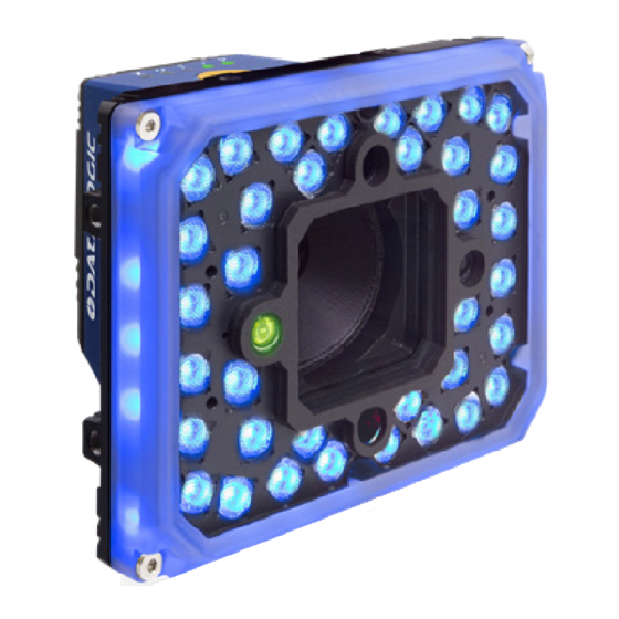
36 LEDs Illuminator

| 1 | Button (Camera Reset - Loader) |
| 2 | Lens Cover |
| 3 | Lens |
| 4 | Focus Adjustment Screw (on side) |
| 5 | Red Spot |
| 6 | Green Spot |
| 7 | Lens Cover Screws |
| 8 | Internal Illuminator |
| 9 | Bracket Mounting Holes (4) |
| 10 | Gigabit Ethernet Connection LED |
| 11 | Gigabit Ethernet Connector |
| 12 | Power - Serial Interfaces - I/O Connector |
| 13 | Power On LED |
| 14 | Illuminator Screws |
INSTALLATION PROCEDURE
- Physically mount the P2x-Series reader.
- All the necessary firmware is installed on the P2x-Series at the factory. Install VPM Software (Vision Program Manager) on an host PC. Machine Vision installation software can be downloaded from the Datalogic website (www.datalogic.com). Refer to the Impact Reference Guide for programming details.
- Make the necessary electrical connections. Camera commununication is provided through the GigaEthernet port. Use the Datalogic cable CAB-ETH-Mxx. Maximum cable length is 10 meters.
- Start VPM.
- Choose the camera.
- If the default IP mask and address work for your installation, you don't need to change them. Otherwise, you can modify the settings.
- To enable the illuminator go to the Settings Tab. Select Camera and choose the Illuminator Tab. Go to Mode then set the Illuminator's operating mode to Normal or Power.
- In the Settings Tab, select Camera then choose the desired photometric parameters and the trigger type.
- Load an existing Vision Program file or create a new one.
- Put the camera online.

M12 17-pole male Power, COM, and I/O connector
| Pin | Name | Description |
| 1 | Vdc | Power supply input voltage + |
| 2 | GND | Power supply input voltage - |
| Connector case | CHASSIS | Connector case provides electrical connection to the chassis |
| 6 | I1A | External Trigger A (polarity insensitive) |
| 5 | I1B | External Trigger B (polarity insensitive) |
| 13 | I2A | Input 2 A (polarity insensitive) |
| 3 | I2B | Input 2 B (polarity insensitive) |
| 9 | O1 | Output 1 * |
| 8 | O2 | Output 2 * |
| 16 | O3 | Output 3 |
| 14 | RX | Reserved |
| 4 | TX | Reserved |
| 17 | Main Interface (SW selectable) | TX: RS232 Transmit |
| 11 | RX: RS232 Receive | |
| 12 | Reserved | |
| 10 | Reserved |
* Output 1 and Output 2 are opto-coupled when using a CBX.

M12 X-Coded female Ethernet Network connector
| Pin | Name | Description |
| 1 | DA+ | Bidirectional data DA+ |
| 2 | DA- | Bidirectional data DA- |
| 3 | DB+ | Bidirectional data DB+ |
| 4 | DB- | Bidirectional data DB- |
| 5 | DD+ | Bidirectional data DD+ |
| 6 | DD- | Bidirectional data DD- |
| 7 | DC- | Bidirectional data DC- |
| 8 | DC+ | Bidirectional data DC+ |
STATUS LED AND BUTTON


| 1 | Power | On - camera is connected to power |
| 2 | ETH | On - Gigabit Ethernet link is established. Blinking - data transmission |
| 3 | Busy | LED blinks during task execution and flash memory access |
| 4 | Out 1 | On - Output 1 is on |
| 5 | Out 2 | On - Output 2 is on |
| 6 | Out 3 | On - Output 3 is on |
| 7 | Online | On - Loaded task will be executed based on their trigger parameters |
| 8 | Button | Camera Reset: restores the default camera settings. Loader: the device will enter the Loader program sequence and the LEDs will begin to cycle through various patterns. Camera Button Event: press and release the button (Internal software event only) |
ILLUMINATOR AND LENS REPLACEMENT

Disconnect the power before removing the cover.
Toolset required
- 2.5 mm Allen Wrench Spacer
- Flat blade screwdriver (max. width 1.2 mm)
To remove the cover
Using the 2.5 mm Allen Wrench remove the lens cover screws and carefully remove the cover. Be sure the sealing gasket stays with the cover.

To remove the camera micro-lens
 NOTE: Adjust the focus to "NEAR" to easily handle the micro-lens.
- Remove the cover and the illuminator.
- Grasp the lens firmly, then press until the lens stops moving.
- Turn the lens 90° counter-clockwise.
- Lift the lens stright up until it clears the lens housing.
To replace the camera micro-lens
- Align the tabs on the lens with the notches in the lens housing.
- Grasp the lens firmly, then press in until the lens stops moving.
- Turn the lens 90° clockwise.
- Release the lens.
- When the lens is mounted, it should not turn in the housing.
- Mount the illuminator or the spacer.


- Carefully put the cover back on. Be sure the sealing gasket fits into the grooves in the camera body.
- Mount the four cover screws. Over tightening can damage the cover. Maximum tightening torque 0.8 N m
To remove and replace the internal illuminator (14 LEDs)
- Remove the four lens cover screws and the cover.
- Unscrew the four threaded spacers using the flat-blade screw-driver, then remove the illuminator.
- Align the new illuminator with the camera case and gently press down until the illuminator is tight to the case.
- Tighten the four new illuminator threaded spacers. Maximum tightening torque 1.2 N m
- Position the cover and replace the four cover screws. Maximum tightening torque 0.8 N m
To remove and replace the internal illuminator (36 LEDs)
- Place the camera on a flat-surface, such as the illuminator side faces downwards. Remove the four illuminator screws and the illuminator.
- Turn the camera case as the illuminator side faces upwards. Align the new illuminator with the case and gently press down until the illuminator is tight to the case.
- Turn the camera upside down. Hold it firmly with both hands to be sure that the illuminator stays with the case.
- Replace the four illuminator screws. Maximum tightening torque 0.8 N m
To replace the optional Yag Cut lens filter
- Remove the four cover screws and carefully remove the cover.
- Gently squeeze the clips on each side of the filter holder while you gently pull straight up from the illuminator.
- Align the Poron filter holder to the lens. Gently squeeze the clips on each side of the filter holder while you gently press straight down on the filter.


TECHNICAL SPECIFICATIONS
Electrical Features
| Power | |
| Supply Voltage | 24 Vdc ± 10% |
| Consumption (including accessory internal illuminator) | 14 LEDs illuminator: 0.42 A, 10 W max.; 36 LEDs illuminator: 0.62 A, 15 W max. |
Communication interfaces
| Gigabit Ehternet | 1000 Mbit/s (supports application protocols: TCP/ IP, EtherNet/IP, Profinet IO, Modbus TCP) |
| RS232 | 2400 to 115200 bit/s |
| Inputs Input 1 (External Trigger) and Input 2 | Opto-isolated and polarity insensitive |
| Max. Voltage | 30 Vdc |
| Max. Input Current | 10 mA |
Electrical Features
| Outputs1 Output 1 - Output 2 | NPN or PNP short circuit protected Opto-isolated only when connected to CBX500/800 |
| Output 3 | NPN or PNP short circuit protected Opto-isolated only when connected to CBX800 Strobe signal is shared with Output 3. Output 3 is active only if the External Strobe is disabled. |
| VOUT (ILOAD = 0 mA) max. | 24 Vdc |
| VOUT (ILOAD = 100 mA) max. | 3 Vdc |
| ILOAD max. | 100 mA |
Optical Features
| Image Sensor | CMOS with Global Shutter |
| Image | Color, Monochrome |
| Pixel size | 2.0 Mpixel: 2.8 µm square qHD: 5.6 µm square |
| Image Format | 2.0 Mpixel: qHD: 960x540 |
| Imager Size | 6.168 µm diagonal 1/2.8 inches |
| Max. Frame Rate (sensor) | 60 frame/s |
| LED Safety | according to EN 62471 |
| Lighting System | Internal illuminator (14 or 36 LEDs) and External Strobe (Output 3) |
Environmental Features
| Operating temperature2 | -10° to 50° (14 to 122°F) |
| Storage Temperature | -20° to 70°C (-4 to158°F) |
| Max. Humidity | 90% non condensing |
| Vibration Resistance EN 60068-2-6 | 14 mm @ 2 to 10 Hz; 1.5 mm @ 13 to 55 Hz; 2 g @ 70 to 500 Hz; 2 hours on each axis |
| Bump Resistance EN 60068-2-29 | 30g; 6 ms; 5000 shocks on each axis |
| Shock Resistance EN 60068-2-27 | 30g; 11 ms; 3 shocks on each axis |
| Protection Class EN 605293 | IP65/IP67 |
Physical Features
| 14 LEDs illuminator | 36 LEDs illuminator | |
| Dimensions (with lens cover) | H x W x L 109x54x56 mm (4.3x2.1x2.2 in.) | H x W x L 116x126x70 mm (4.6x4.9x2.8 in.) |
| Weight | about 380g. (13.4 oz.) | about 640g. (22.5 oz.) |
| Material | Aluminium | |
User interface
| LED indicators | Power, Busy/Trigger, Out 1; Out 2; Out 3, Online |
| Keypad Button | Reset; Camera Button Event (internal software event only); Loader |
Hardware features
| Storage | 380 MB |
| RAM | 1 GB |
1When connected to the CBX connection boxes, the electrical features for Output 1 and 2 become the following:
Opto-isolated, VCE = 30 Vdc max.; ICE = 40 mA continuous max.; 130 mA pulsed max.; VCE saturation = 1 Vdc max. @ 10 mA; PD = 90 mW max. @ 50°C ambient temperature.
2High ambient temperature applications should use metal mounting brackets for heat dissipation.
3When correctly connected to IP67 cables with seals and the Lens Cover is correctly mounted.

Documents / Resources
References
Download manual
Here you can download full pdf version of manual, it may contain additional safety instructions, warranty information, FCC rules, etc.
Download Datalogic P2X Series - Industrial Smart Camera Quick Reference Guide
Advertisement


Need help?
Do you have a question about the P2X Series and is the answer not in the manual?
Questions and answers