
Subscribe to Our Youtube Channel
Related Manuals for Datalogic P2x-Series


Summary of Contents for Datalogic P2x-Series
- Page 1 P2x-Series™P2x-Series™P2x-Series™ P2X-Series™ PRODUCT REFERENCE GUIDE Industrial Smart Camera...
- Page 2 Electronic versions of this document may be downloaded from the Datalogic website (www.datalogic.com). If you visit our website and would like to make comments or suggestions about this or other Datalogic publications, please let us know via the "Contact" page.
-
Page 3: Table Of Contents
Package contents ......................21 Mechanical Dimensions ....................22 P2x-Series™ (14 LEDs ILLUMINATOR) ...................22 P2x-Series™ (36 LEDs ILLUMINATOR) ...................25 Mounting and positioning the P2x-Series™ ..............29 Mounting Brackets ..........................29 CHAPTER 4. ELECTRICAL CONNECTIONS..............31 On board Gigabit Ethernet Interface ................31 On-board Gigabit Ethernet Connector ....................31... - Page 4 CBX Electrical Connections .....................34 Power Supply .........................36 Inputs ..........................36 EXTERNAL TRIGGER INPUT CONNECTIONS USING P2x-Series™ POWER ........37 EXTERNAL TRIGGER INPUT CONNECTIONS USING EXTERNAL POWER ........38 INPUT 2 CONNECTIONS USING P2x-Series™ POWER ..............39 INPUT 2 CONNECTIONS USING EXTERNAL POWER ..............40 Outputs ..........................40...
-
Page 5: Preface
TECHNICAL SUPPORT Support Through the Website Datalogic provides several services as well as technical support through its website. Log on to (www.datalogic.com). For quick access, from the home page click on the search icon , and type in the name of the product you’re looking for. -
Page 6: Reseller Technical Support
A reseller is acquainted with specific types of businesses, application software, and computer systems and can provide individualized assistance. All necessary firmware is installed on the P2x-Series™ camera at the factory. Vision Pro- gram Manager (VPM) software must be installed to configure the camera inputs, strobe, general purpose outputs, and internal illuminators. -
Page 7: Led Safety
HANDLING Led Safety For all Datalogic P2X compatible internal illuminators, LED emission is classified as Risk Group 1 according to EN 62471: 2010. HANDLING The P2x-Series™ camera is designed to be used in an industrial environment and is built to withstand vibration and shock when correctly installed. However, it is also a precision product and it must be handled correctly before and during installation to avoid damage. - Page 8 PREFACE • Do not weld the camera into position. This can cause electrostatic, heat, or imager damage, • Do not spray paint near the camera. This can cause lens or imager damage. viii P2X-SERIES™...
-
Page 9: Chapter 1. Introduction
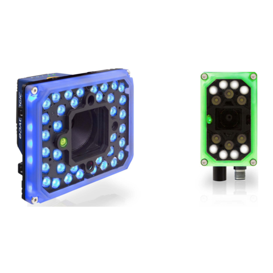
CHAPTER 1 INTRODUCTION GENERAL VIEW Disconnect power before removing the cover. CAUTION P2x-Series™ (14 LEDs ILLUMINATOR) Connector block rotates to 90° position Lens cover Lens Button (Camera Reset - Loader) Bracket Mounting Holes (4) Focus Adjustment Screws (4) Gigabit Ethernet Connection LED... -
Page 10: P2X-Series™ (36 Leds Illuminator)
INTRODUCTION P2x-Series™ (36 LEDs ILLUMINATOR) Connector block rotates to 90° position Button (Camera Reset - Loader) Internal Illuminator Lens Cover Bracket Mounting Holes (4) Lens Gigabit Ethernet Connection LED Focus Adjustment Screw (on side) Gigabit Ethernet Connector Red Spot Power - Serial Interfaces - I/O Connector... -
Page 11: Product Description
Do not remove the heatsink from the camera body to avoid overheating. CAUTION Product Description The P2x-Series™ cameras are Datalogic industrial compact 2D cameras produced to be a high performance affordable solution for all machine vision applications. The P2x-Series™ cameras are designed to be flexibly assembled for all machine vision applications. - Page 12 The following diagrams list the operating distances for various cameras using a 14 LEDs illuminator or the spacer. The operating distance using a 36 LEDs illuminator is 15 mm shorter. To calculate the Vertical Field of View use this formula: V * 9/16 P2X-SERIES™...
- Page 13 GENERAL VIEW PRODUCT REFERENCE GUIDE...
-
Page 14: Indicators And Keypad Button
LED blinks during task execution and flash memory access Out 1 On – Output 1 is on Out 2 On – Output 2 is on Out 3 On – Output 3 is on On – Loaded tasks will be executed based on their trigger Online parameters P2X-SERIES™... -
Page 15: Lighting System And Lens Notes For 14 And 36 Leds Illuminators
3. The device restarts automatically. Lighting System and Lens Notes for 14 and 36 LEDs illuminators The following table shows the lenses and illuminators for the P2x-Series. The blue checkbox indicates the recommended combinations, the green check-box indicates the compatible combinations. Illuminators are enabled in VPM – Camera Setup. -
Page 16: Necessary Camera Components
Lighting WHT white LTP 110-352 SN14L 35D BLU 475nm LTP 112-352 SN36L 35D BLU 475nm Necessary camera components Configuration A - External Lighting Cover Spacer Lens Body Configuration B1 - 14 LEDs Illuminator Cover Lens Body LTP 14 LED P2X-SERIES™... -
Page 17: Basic Components
GENERAL VIEW Configuration B2 - 36 LEDs Illuminator LTP 36 Lens Body Adapter Basic components PART ACCESSORY DESCRIPTION NUMBER Bases (Body, Spacer and Cover) P20M 100-00 ML P20M-ML 960x540 Mono Micro Lens 937710021 P20C 000-000 ML P20C-ML 960x540 Color Micro Lens 937710022 P22M 700-00 ML P22M-ML 1920x1080 Mono Micro Lens... - Page 18 Various M12 Panel Connectors for CBX Connection Boxes are available Licenses License, Enhanced, Smart Camera 95A900008 License, Pro, Smart Camera 95A900009 Power Supplies PG6002 AC/DC Power Supply Unit (US) 93ACC1718 PG6001 AC/DC Power Supply Unit (UK) 93ACC1719 PG6000 AC/DC Power Supply Unit (EU) 93ACC1720 P2X-SERIES™...
-
Page 19: Chapter 2. Rapid Configuration
Use the PG600x AC/DC Power Supply Unit (3 versions for European, UK or US plug). • Terminal Block Connection Use CAB-DSxx-S between the P2x-Series™ camera and the Terminal Block for power, external trigger device (photocell), and additional I/O connections. PRODUCT REFERENCE GUIDE... -
Page 20: Cbx500/Cbx800 Pinout For P2X-Series
RAPID CONFIGURATION Use the CAB-ETH-X-Mxx for the Ethernet connection to the host. The P2x-Series™ does not support sourcing power towards the CBX in order to power I/O devices. These devices must be powered through the CBX or from an external source. -
Page 21: Step 2 - Install The Lens And Illuminator
STEP 2 – INSTALL THE LENS AND ILLUMINATOR STEP 2 – INSTALL THE LENS AND ILLUMINATOR Continue with this step if the camera has no lens or internal illuminator, or you want to use a lens or illuminator with different characteristics. If the camera already contains the correct lens and illuminator, continue with Step 3. - Page 22 Figure 3 - Aligning the cover (14 and 36 LEDs models) 2. Place the new cover on the reader and press the cover frame edges. To avoid damage, do not press on the window. CAUTION P2X-SERIES™...
- Page 23 STEP 2 – INSTALL THE LENS AND ILLUMINATOR 3. Insert the four screws and loosely tighten them in a clockwise direction. 4. Finally tighten the screws to a maximum torque of 0.8 N m. To remove the camera micro-lens Lens release position Lens lock position Adjust the focus to “NEAR”...
- Page 24 3. Turn the camera upside down. Hold it firmly with both hands to be sure that the illuminator stays with the case. 4. Replace the four illuminator screws. Maximum tightening torque 0.8 N m. Configure an Internal Illuminator in VPM - Camera Setup (See “Startup” on page 46.) NOTE P2X-SERIES™...
- Page 25 STEP 2 – INSTALL THE LENS AND ILLUMINATOR To replace the optional Yag Cut lens filter The reader must be disconnected from the power supply during the proce- dure. CAUTION Make sure to operate in a dust-free environment during the cover replace- ment procedure.
-
Page 26: Step 3 - Mount And Position The Camera
RAPID CONFIGURATION STEP 3 – MOUNT AND POSITION THE CAMERA Use the P2x-Series™ mounting brackets to obtain the most suitable position for the camera. The most common mounting configurations are shown in the figures below. 14 LEDs Illuminator Pitch Tilt Figure 4- 14 LEDs Illuminator with STD Fix Bracket This mounting position is valid also for Configuration A - External Lighting. - Page 27 STEP 3 – MOUNT AND POSITION THE CAMERA Position 2 Skew Tilt Figure 6 - 36 LEDs Illuminator, front extended positioning with Pivot Fix Bracket Position 3 Tilt Skew Figure 7 - 36 LEDs Illuminator, side extended positioning with Pivot Fix Bracket Position 4 Tilt Skew...
-
Page 28: Step 4 - Focus The Camera
Figure 9 - Pitch, Tilt and Skew Angles STEP 4 – FOCUS THE CAMERA To adjust the P2x-Series™ lens, use VPM to continuously snap and display an image. Use the camera Focus adjustment on the side of the camera to adjust the focus. -
Page 29: Chapter 3. Installation
CHAPTER 3 INSTALLATION PACKAGE CONTENTS Verify that the P2x-Series™ camera and all the parts supplied with the equipment are present and intact when opening the packaging; the list of parts includes: 1. P2x-Series™ camera (base + spacer + camera) 2. Quick Reference Guide 3. -
Page 30: Mechanical Dimensions
INSTALLATION MECHANICAL DIMENSIONS The P2x-Series™ cameras can be installed to operate in different positions. The four screw holes (M4 x 6) on the body of the camera are for mounting the heatsink to the camera and this latter to the provided brackets. The diagram below gives the overall dimensions of the camera and may be used for its installation. - Page 31 MECHANICAL DIMENSIONS [in] Figure 3 - Overall Dimensions with Connector at 90° PRODUCT REFERENCE GUIDE...
- Page 32 INSTALLATION Figure 4- STD Fix Bracket Overall Dimensions P2X-SERIES™...
-
Page 33: P2X-Series™ (36 Leds Illuminator)
MECHANICAL DIMENSIONS P2x-Series™ (36 LEDs ILLUMINATOR) The P2x-Series ™ cameras 36 LEDs can be mounted horizontally and vertically. Connector block [in] rotates to 90° position Figure 5 - Overall Dimensions with Connector at 0° PRODUCT REFERENCE GUIDE... - Page 34 INSTALLATION Figure 6 - Overall Dimensions with Connector at 90° P2X-SERIES™...
- Page 35 MECHANICAL DIMENSIONS Figure 7 - Pivot Fix Bracket for 36 LEDs Illuminator - large (BK-32-010) PRODUCT REFERENCE GUIDE...
- Page 36 INSTALLATION Figure 8 - Pivot Fix Bracket for 36 LEDs Illuminator - small (BK-32-010) P2X-SERIES™...
-
Page 37: Mounting And Positioning The P2X-Series
The Pivot Fix Bracket is included in the 36LEDs illuminator’s box. NOTE Use the P2x-Series™ mounting brackets to obtain rotation on the various axes of the camera as shown in the diagram below: Figure 11 - 14 LEDs Illuminator with STD Fix Bracket (connectors at 0° and 90°) This mounting position is valid also for Configuration A - External Lighting. - Page 38 Figure 12 - 36 LEDs Illuminator with STD Fix Bracket Figure 13 - 36 LEDs Illuminator side positioning with Pivot Fix Bracket (connectors at 0° and 90°) Figure 14 - 36 LEDs Illuminator front extended positioning with Pivot Fix Bracket (illuminator horizontally mounted) P2X-SERIES™...
-
Page 39: Chapter 4. Electrical Connections
CHAPTER 4 ELECTRICAL CONNECTIONS ON BOARD GIGABIT ETHERNET INTERFACE The on-board Gigabit Ethernet Interface can be used for TCP/IP communication with a remote or local host computer by connecting the camera to either a LAN or directly to a host PC. On-board Gigabit Ethernet Connector A Standard M12 X-Coded female connector is provided for the on-board Gigabit Ether- net connection. -
Page 40: Rs232 Interface
The Impact software does not support RS485 protocol. Auxiliary RS232 Interface The 9-pin female Auxiliary Interface connector inside the CBX is to be used by Factory and Support personnel only. Do not make any connections to the Aux Interface. NOTE P2X-SERIES™... -
Page 41: Terminal Block Connections
TERMINAL BLOCK CONNECTIONS TERMINAL BLOCK CONNECTIONS The connector pinouts and notes given in this chapter are for custom cabling applica- tions. Power, COM and I/O Connector The CAB-DSxx-S cable has an M12 17-pin connector on the camera end and a 25-pin male D-sub connector on the other end. -
Page 42: Cbx Electrical Connections
CBX ELECTRICAL CONNECTIONS All P2x-Series™ configurations can be connected to a CBX500 or CBX800 connection box through one of the available CAB-DSxx-S accessory cables. These accessory cables ter- minate in an M12 17-pin connector on the camera side and in a 25-pin male D-sub con- nector on the CBX side. - Page 43 CBX ELECTRICAL CONNECTIONS CBX500/800 TERMINAL BLOCK CONNECTORS Input Power Power Supply Input Voltage + Power Supply Input Voltage - Earth Protection Earth Ground Inputs Power Source - External Trigger External Trigger + or - (polarity insensitive) External Trigger + or - (polarity insensitive) Power Reference - External Trigger Power Source - Inputs Input 2 + or - (polarity insensitive)
-
Page 44: Power Supply
Polarity insensitive inputs are full functionality even if pins A and B are exchanged. NOTE The connections are indicated in the following diagrams: CBX500/800 FUNCTION Power Source - External Trigger External Trigger A (polarity insensitive) External Trigger B (polarity insensitive) Power Reference - External Trigger P2X-SERIES™... -
Page 45: External Trigger Input Connections Using P2X-Series™ Power
Device on the +V/-V spring clamps, and does not pass through the Power Switch (ON/OFF) inside the CBX. Disconnect all power supplies when CAUTION working inside the CBX. Figure 3 - PH-1 External Trigger Using P2x-Series™ Power Figure 4 - NPN External Trigger Using P2x-Series™ Power PRODUCT REFERENCE GUIDE... -
Page 46: External Trigger Input Connections Using External Power
Figure 5 - PNP External Trigger Using External Power Figure 6 - NPN External Trigger Using External Power CBX500/800 FUNCTION Power Source - Inputs Input 2 + or - (polarity insensitive) Input 2 + or - (polarity insensitive) Power Reference - Inputs P2X-SERIES™... -
Page 47: Input 2 Connections Using P2X-Series™ Power
Device on the +V/-V spring clamps, and does not pass through the Power Switch (ON/OFF) inside the CBX. Disconnect all power supplies when CAUTION working inside the CBX. Figure 7 - PNP Input 2 Using P2x-Series™ Power Figure 8 - NPN Input 2 Using P2x-Series™ Power PRODUCT REFERENCE GUIDE... -
Page 48: Input 2 Connections Using External Power
When Outputs 1 and 2 are connected through the CBX connection box, you must set the Output Type configuration parameters to NPN. NOTE The outputs are programmed using VPM. 1. Start VPM 2. Select the General icon. 3. Select the Communication button. P2X-SERIES™... - Page 49 OUTPUTS Select NPN for the output type. Outputs are typically used either to signal the data collection result or to control an external lighting system. CBX500/800 FUNCTION Power Source - Outputs Output 1 + opto-isolated and polarity sensitive Output 1 - opto-isolated and polarity sensitive Output 2 + opto-isolated and polarity sensitive Output 2 - opto-isolated and polarity sensitive CBX500: 03A...
-
Page 50: Output 1 And 2 Connections Using P2X-Series™ Power
Switch (ON/OFF) inside the CBX. Disconnect all power supplies when NOTE working inside the CBX. Figure 11 - PNP/Open Emitter Output Using P2x-Series™ Power Figure 12 - NPN/Open Collector Output Using P2x-Series™ Power OUTPUT 1 AND 2 CONNECTIONS USING EXTERNAL POWER Figure 13 - PNP/Output Open Emitter Using External Power P2X-SERIES™... -
Page 51: Output 3 Connections Using P2X-Series™ Power (Cbx500 Only)
The CBX500 or CBX800 must be used to connect this output. OUTPUT 3 CONNECTIONS USING P2x-Series™ POWER (CBX500 Only) Figure 15 - Output 3 Using P2x-Series™ Power OUTPUT 3 CONNECTIONS USING EXTERNAL POWER (CBX500 Only) Figure 16 - Output 3 Using External Power Do not connect to I3A or I34B Signals, they are reserved. -
Page 52: Output 3 Connections Using P2X-Series™ Power (Cbx800 Only)
ELECTRICAL CONNECTIONS OUTPUT 3 CONNECTIONS USING P2x-Series™ POWER (CBX800 Only) Figure 17 - Output 3 Using P2x-Series™ Power OUTPUT 3 CONNECTIONS USING EXTERNAL POWER (CBX800 Only) Figure 18 - Output 3 Using External Power Outputs Three general purpose non opto-isolated but short circuit protected outputs are avail- able on the M12 17-pin connector. - Page 53 User Interface Vext 9/8/16 Figure 20 - NPN Output Connection For NPN output connections, the external interface voltage (Vext) must not exceed the P2x-Series™ power supply source voltage (Vdc) otherwise correct output functioning cannot be guaranteed. CAUTION PRODUCT REFERENCE GUIDE...
-
Page 54: Chapter 5. Software Configuration
After completing the mechanical and electrical connections to P2x-Series™ camera, you can begin software configuration as follows: 1. Power on the P2x-Series™ camera. Wait for the camera startup. The system boot- strap requires about 30 seconds to be completed. 2. Run VPM. - Page 55 STARTUP 4. (Optional step) To update the Smart Camera Firmware click the button. The firm- ware update dialog will appear. Package is automatically selected and loaded. 5. When the connection is complete, click the Settings tab. 6. Click the camera icon, click the Setup tab, then click the Setup button below the image window.
- Page 56 SOFTWARE CONFIGURATION 8. Click the Illuminator tab to configure the P2x-Series™ camera’s internal illumina- tor. The illuminator settings will affect the shutter Open Time range. MODE This sets the Internal Illuminator’s operating mode (Disabled, Normal, Power). This also affects the permitted Shutter Open Time range.
- Page 57 STARTUP 2. decrease the Exposure Shutter Open Time Figure 2 - Example Over Exposure: Too Light MODEL This box contains the model name of the Internal Illuminator mounted on the camera, and the number of Lighting Chains that the Illuminator contains. LIGHTING CHAINS •...
- Page 58 The pictures below display the relative position on the illuminator. Illuminator Vertical Position Chain 5 Chain 4 Chain 6 Chain 3 Chain 1 Chain 2 Illuminator Horizontal Position Chain 6 Chain 1 Chain 5 Chain 2 Chain 4 Chain 3 P2X-SERIES™...
-
Page 59: Calibration
CALIBRATION CALIBRATION VPM provides calibration software to insure that the measurements indicated in VPM tools accurately relate to the inspected object’s measurements. You may calibrate a camera using a calibrated target, a part with known dimensions, or you can enter the camera’s units-per-pixel factor manually. -
Page 60: Chapter 6. Illuminators
One Image Acquisition Setting could enable and use an inter- nal illuminator and another setting could enable and use an external lighting system. The P2x-Series offers two Illuminators options (14 or 36 LEDs) and standard or polarized cover to remove LED reflection. -
Page 61: Cover
Glossy labels • Labels under plastic films By removing LED reflection, P2x-Series™ with polarized illuminators features extreme mounting flexibility, as it can be mounted 90° to the target surface. This in turn avoids code distortion and allows more reliable code grading. -
Page 62: Lightning
Coaxial Field Illumination When the light hits the surface, most of it will reflect away from the lens and produce a dark image. Coaxial lights hit the surface perpendicular to the object plane providing a diffuse illumination and reducing shadowing. P2X-SERIES™... - Page 63 LIGHTNING Dark Field Illumination Lighting of surfaces at wide angles used to avoid direct reflection of the light into the camera’s lens. Typically this type of lighting is used in solutions to enhance reflectance of the uneven surface. It is also used with very reflective surfaces. Structured Field Illumination The light is projected with a known shading pattern on the target.
-
Page 64: Chapter 7 Maintenance
Impact Reference Guide. • If you’re unable to fix the problem and you’re going to contact your local Datalogic office or Datalogic Partner, we suggest providing (if possible): software version, Serial Number, and Order Number of your camera. You can get some of this infor- mation while VPM is connected to the camera. - Page 65 TROUBLESHOOTING TROUBLESHOOTING GUIDE Problem Suggestion • Check if you are referring to the 19-pin connector or to the CBX spring clamp connectors. • Is the sensor connected to Input 1 or Input 2? • Is power supplied to the photo sensor? Using Input 1 (External •...
-
Page 66: Chapter 8. Technical Features
Pixel Size µ m square qHD: 5.6 m square 2.0 Mpixel : 1920x1080 Image Format qHD: 960 × 540 6.18 µ m diagonal Imager Size 1/2.8 inches Max. Frame Rate (sensor) 60 frames/sec Led Safety according to EN 62471 P2X-SERIES™... - Page 67 ELECTRICAL FEATURES Lighting System Internal Illuminator (14 or 36 LEDs) and External Strobe (Output 3) ENVIRONMENTAL FEATURES -10 to 50°C (14 to 122°F) Operating Temperature Storage Temperature -20° to 70°C (-4 to 158°F) Max. Humidity 90% non condensing 14 mm @ 2 to 10 Hz; 1.5 mm @ 13 to 55 Hz; Vibration Resistance EN 60068-2-6 2 g @ 70 to 500 Hz;...
-
Page 68: Optical Sensor Response
TECHNICAL FEATURES Optical sensor response P2X-SERIES™... -
Page 69: Glossary
GLOSSARY BARCODES (1D CODES) A pattern of variable-width bars and spaces which represents numeric or alphanumeric data in machine-readable form. The general format of a barcode symbol consists of a leading margin, start character, data or message character, check character (if any), stop character, and trailing margin. - Page 70 (Charge Coupled Devices) or CMOS (Complementary Metal Oxide Semiconductor) pixel sensors. INTERNAL ILLUMINATOR The strobe illuminator that is an integral part of the lens cover for the P2x-Series™. IP ADDRESS The terminal’s network address. Networks use IP addresses to determine where to send data that is being transmitted over a network.
- Page 71 TCP/IP is the primary protocol that defines the Internet. VISION PROGRAM MANAGER (VPM) The Impact software module that provides tools to configure the P2x-Series™ camera and create vision programs for inspection and control. Throughout this manual, the name “VPM” is used to refer to the software installed on the camera.
- Page 72 © 2021 Datalogic S.p.A. and /or its affiliates • All rights reserved • Without limiting the rights under copyright, no part of this documentation may be reproduced, stored in or introduced into a retrieval system, or transmitted in any form or by any means, or for any purpose, without the express written permission of Datalogic S.p.A.
Need help?
Do you have a question about the P2x-Series and is the answer not in the manual?
Questions and answers