Datalogic AV7000 Reference Manual
Linear camera
Hide thumbs
Also See for AV7000:
- Product reference manual (352 pages) ,
- Product reference manual (488 pages)
Table of Contents
Advertisement
Quick Links
Advertisement
Table of Contents

Related Manuals for Datalogic AV7000


Summary of Contents for Datalogic AV7000
- Page 1 > AV7000 Linear Camera...
- Page 2 This manual refers to software version 2.0.0 and later. © 2016 - 2017 Datalogic S.p.A. and/or its affiliates ALL RIGHTS RESERVED. Without limiting the rights under copyright, no part of this documentation may be reproduced, stored in or introduced into a retrieval system, or transmitted in any form or by any means, or for any purpose, without the express written permission of Datalogic S.p.A.
-
Page 3: Table Of Contents
Reading Station Overview .................... 1 Image Acquisition ......................3 Pulsed Illumination ......................4 Applications ........................5 Model Description ......................6 AV7000 and AI7000 versions ..................6 External Function Buttons (HMI – Human Machine Interface) ........7 Accesories ........................8 1.10 Photoelectric Sensor ....................11 1.11... - Page 4 2.4.8 Illuminator Bracket Pre-Assembly and Mounting ............27 2.4.9 AV7000 Bracket Angles ....................33 2.4.10 Alternative Camera Mounting Between Rails ............. 35 2.4.11 Mounting the AV7000 Camera to the AI7000 Illuminator ........... 36 Installing the Deflection Mirror ..................39 2.5.1 Deflection Mirror Bracket Angles ................40 2.5.2 Alternative Deflection Mirror Mounting Between Rails ..........
- Page 5 IMAGING FEATURES ....................212 First-time Startup ...................... 212 5.1.1 Default Parameters ....................212 Focus Device Setup ....................213 5.2.1 Setting up AV7000 Focus Using a DM3610 Dimensioner ........213 5.2.2 Installing and Calibrating a RangeFinder for Focusing in an AV7000 System ..221...
- Page 6 5.2.3 Setting up an AV7000 System Using an LCC-75XX KIT with DS2 Light Array ..233 AV7000 Camera Setup and Calibration ..............236 5.3.1 e-Genius Calibration Presets ..................238 5.3.2 Calibrating AV7000: Static Calibration ..............241 5.3.3 Calibrating AV7000: Dynamic Calibration ..............247 Final Acceptance Test ....................
-
Page 7: References
REFERENCES REFERENCE DOCUMENTATION The documentation related to the AV7000 camera system management is listed below: DM3610 Reference Manual RangeFinder FRU Guide DS2 Instruction Manual PWR-480B Installation Manual SUPPORT THROUGH THE WEBSITE Datalogic provides several services as well as technical support through its website. Access www.datalogic.com and click on the SUPPORT >... -
Page 8: Conventions
CONVENTIONS WARNING or CAUTION: This symbol identifies a hazard or procedure that, if incorrectly performed, could cause personal injury or result in equipment damage. It is also used to bring the user’s attention to details that are considered IMPORTANT. HIGH VOLTAGE CAUTION: This symbol alerts the user they are about to perform an action involving, either a dangerous level of voltage, or to warn against an action that could result in damage to devices or electrical shock. -
Page 9: Warning And Serial Labels
LED light. Avoid staring at the LEDs as one would with any very strong light source, such as the sun. WARNING: There are no user-serviceable parts inside the reader. Service should only be performed by Datalogic trained and certified technicians. -
Page 10: Power Supply
The EU declaration of conformity is available for competent authorities and customers through Datalogic commercial reference contacts. Since April 20th, 2016 the main European directives applicable to Datalogic products require inclusion of an adequate analysis and assessment of the risk(s). This evaluation was carried out in relation to the applicable points of the standards listed in the Declaration of Conformity. -
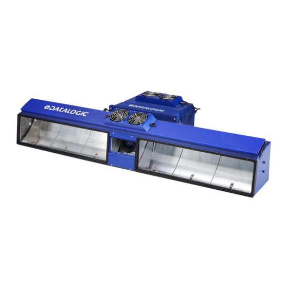
Page 11: General View
GENERAL VIEW Figure 2: AV7000 Camera Front View Figure 3: AV7000 Camera Back View... -
Page 12: Field Procedure Quick Cross Reference
FIELD PROCEDURE QUICK CROSS REFERENCE: DM3610 Focusing/Calibration, see section 5.2.1 RangeFinder Focusing/Calibration, see section 5.2.2 DS2 Light Array Calibration, see section 5.2.3 AS1 Area Sensor Alignment, see section 5.7 Camera Calibration – Static, see section 5.3.2 ... -
Page 13: Introduction
1 INTRODUCTION 1.1 PRODUCT DESCRIPTION The AV7000 Camera is a high performance linear camera with an integrated image processing system dedicated to automatic code identification on moving parcels. This chapter introduces a minimum set of concepts necessary for camera installation and setup. - Page 14 (photoelectric sensors, encoders, height sensors, and etc.). A typical reading station will also include: Power Supply Systems: The AV7000 requires a 24 Vdc power supply. Usually each barcode reader-illuminator pair has its own power supply system (i. e. PWR-480B).
-
Page 15: Image Acquisition
1.3 IMAGE ACQUISITION Each barcode reader contains two distinct groups of devices: The acquisition device or "camera." This part of the AV7000 has to work in strict real time to acquire the best possible images. The decoding device or “decoder." This part of the AV7000 interprets the data received through the camera. -
Page 16: Pulsed Illumination
AV7000 LINEAR CAMERA REFERENCE MANUAL 1.4 PULSED ILLUMINATION When building multi-camera stations with standard continuous light illuminators, the illumination areas must be accurately chosen to avoid the illuminator of one camera disturbing the acquisition of another camera. In particular the lobes of the side camera illuminators must not cross over the conveyor belt. -
Page 17: Applications
INTRODUCTION 1.5 APPLICATIONS The AV7000 cameras are specifically designed for industrial applications and for all cases requiring high reading performance such as: Reading low aspect ratio barcodes Reading of codes covered by plastic film Reading of codes with a large depth of field ... -
Page 18: Model Description
AV7000 LINEAR CAMERA REFERENCE MANUAL 1.6 MODEL DESCRIPTION AV7000 cameras are available in versions that differ depending on the optical resolution (focus range), while the AI7000 illuminators differ depending on the illuminated reading width: AV7000 - 1 X 0 0... -
Page 19: External Function Buttons (Hmi - Human Machine Interface)
1.8 EXTERNAL FUNCTION BUTTONS (HMI – HUMAN MACHINE INTERFACE) The AV7000 camera includes two external buttons that can be used to perform specific tasks without the need of connecting to e-Genius (AV7000 browser-based user interface). See section 5.9 for functional description. -
Page 20: Accesories
AV7000 LINEAR CAMERA REFERENCE MANUAL 1.9 ACCESORIES The following accessories are available on request for the AV7000 Camera Imaging System. Description Part Number AV7000 CAMERA HEADS INDIVIDUAL HEADS AV7000-1000 140MM F/5.6 934001000 AV7000-1100 140MM F/5.6 SHORT RANGE 934001010 AV7000-1200 110MM F/8.0... - Page 21 HOST AND IMAGE NETWORK CABLES CAB-9E05 RJ45-IP67 CABLE ETHERNET 5M 93A051364 CAB-9E10 RJ45-IP67 CABLE ETHERNET 10M 93A051365 AV7000 TO CBX CABLES CBL AV7-100 M16-IP67 CABLE TO CBX 3M 93A050072 CBL-AV7-101 M16-IP67 CABLE TO CBX 5M 93A050073 CBL-AV7-102 M16-IP67 CABLE TO CBX 10M...
- Page 22 AV7000 LINEAR CAMERA REFERENCE MANUAL Description Part Number BM1210 MODBUS TCP IP65 MODULE 93ACC1849 NOTE: For AV7000 applications, the CBX Fieldbus modules listed above are only used in the CBX800 Gateway. BA100 DIN RAIL ADAPTERS 93ACC1821 BA900 TWO CABLE GLANDS PANEL 93ACC1847 BA300 M12 3P F.
-
Page 23: Photoelectric Sensor
In irregular package applications, the photoelectric sensor assists in maintaining the package footprint so that the AV7000 camera will only scan and provide data for a specific package. -
Page 24: Area Sensor
AV7000 LINEAR CAMERA REFERENCE MANUAL 1.11 AREA SENSOR The photoelectric light grids of the AS1 series are crossed-beam area sensors able to detect all objects, with even 0.2mm thickness, inside a 100mm height, over operating distances reaching 3m between emitter and receiver. The AS1 area sensors represent the ideal solution for the detection of very small objects, even when passing in different positions inside the controlled height and width. -
Page 25: Encoder (Tachometer)
INTRODUCTION 1.12 ENCODER (TACHOMETER) The encoder/tachometer delivers a continuous pulse to the system, which provides feedback on conveyor speed and transmit point, and can be used to help track the package position along the length of the conveyor. See section 3.10.3 and 3.11.3 for wiring options. Figure 13: Encoder/Tachometer, Mounting Bracket, and Cable Encoder (Tachometer) OEK-2 OPTICAL ENCODER (CAB 10m+SPRING) -
Page 26: Pgd100 Non-Contact Speed Detector
AV7000 LINEAR CAMERA REFERENCE MANUAL 1.13 PGD100 NON-CONTACT SPEED DETECTOR The PGD100 is a non-contact position measurement device, or Speed Detector, consisting of a Controller and Sensor Array(s). It is used in cases where a traditional contact encoder/tachometer will not work, as in a Cross-Belt Sorters or Tilt-Tray system where a continuous belt surface is not available. -
Page 27: Cbx Industrial Connection Box
INTRODUCTION 1.14 CBX INDUSTRIAL CONNECTION BOX CBX Series are industrial connection boxes that can be used to connect the barcode readers to an encoder/tachometer, photoelectric sensor, serial devices, relays, or other peripherals. See section 3.10 for wiring options. Figure 15: CBX500, CBX800, and CBX100 Connection Boxes shown CBX Connection Box CBX100 CONNECTION BOX COMPACT 93A301067... -
Page 28: Lcc-75Xx Kit With Ds2 Light Array
AV7000 LINEAR CAMERA REFERENCE MANUAL 1.15 LCC-75XX KIT WITH DS2 LIGHT ARRAY The DS2 Light Array (Light Curtain), part of the LCC-75xx kit, is used to detect the presence of products as they enter the scanning area as well as report the package heights to the system Master. -
Page 29: Rangefinder
INTRODUCTION 1.16 RANGEFINDER The RangeFinder is used to detect the presence of products as they enter the scanning area as well as report the package positions/heights and sequence number to all cameras in the system. RangeFinders can also be used to provide rough dimensioning data. See section 5.2.2 for information on installing and calibrating the RangeFinder. -
Page 30: Dm3610 Dimensioner
See section 0 for information on setting up the DM3610. For complete information about the features and capabilities of the DM3610 Dimensioner, see the dimensioner page on the Datalogic website: www.datalogic.com. Figure 18: DM3610 Dimensioner The DM3610 Dimensioner requires the following: ... -
Page 31: Mechanical Installation
Do not attempt to perform any electrical installation procedures unless you are a trained technician. IMPORTANT: AV7000 cameras contain electronics that may be affected by electrostatic discharge (ESD). To prevent personal injury or damage to the unit, please follow the safety precautions and warnings found in the References section at the beginning of this manual. -
Page 32: Tools Required
AV7000/AI7000, deflection mirror, and brackets, 2.2 UNPACKING INSTRUCTIONS Verify that the AV7000 Camera and all the parts supplied with the equipment are present and intact when opening the packaging; the list of parts includes: Figure 19: AV7000 Camera package contents NOTE: The AV7000 Camera and accessory packaging is designed to protect the unit(s) during shipment. - Page 33 MECHANICAL INSTALLATION Figure 20: AI7000 Illumination package contents Important: Be sure to retain shipping boxes and packing material for use if the unit needs to be returned to Datalogic for any reason.
-
Page 34: Installation Sequence
4. Mount the brackets to the mounting structure 5. Mount the AI7000 Illuminator to its mounting brackets 6. Mount the fan assembly to the AV7000 Camera 7. Mount the AV7000 Camera to the Illuminator 8. Mount the brackets for the deflection mirror, if required. -
Page 35: Installation
Mounting the unit with 300 mm [12 in] of clearance (front, top, and sides) is recommended for cooling and ease of maintenance. Note: The AV7000 datum is indicated by the dashed line. As indicated, the range to the target is measured from the camera/illumination interface plane. -
Page 36: Physical Support Requirements
Datalogic products, parts or related equipment. As you plan and install your AV7000 camera imaging system application, be sure to keep the following guidelines in mind: Follow application drawings for structural details and barcode reader placement. -
Page 37: Scanning Station Frame/Mounting Structure Preparation And Positioning
MECHANICAL INSTALLATION It provides approximately 300 mm [12 in] minimum clearance on all sides. This clearance is necessary to provide proper ventilation, allow access to all panels of the barcode reader, and allow room for proper servicing. 2.4.6 Scanning Station Frame/Mounting Structure Preparation and Positioning The vision system components and in particular the mounting brackets have been designed for installation onto standard Bosch and 80/20 frame profiles (extrusions) and accessories. -
Page 38: Mounting Rails
AV7000 LINEAR CAMERA REFERENCE MANUAL 2.4.7 Mounting Rails The Camera/Illuminator and Deflection Mirror are mounted to mounting structure rails, as shown below. Typically, the rising brackets are mounted to the rails, but in some cases it may be necessary to mount the camera and deflection mirror between the mounting rails. -
Page 39: Illuminator Bracket Pre-Assembly And Mounting
MECHANICAL INSTALLATION 2.4.8 Illuminator Bracket Pre-Assembly and Mounting The mounting brackets have been designed specifically to quicken, simplify and facilitate vision system mounting. These brackets have universal mounting configurations and reference slots for all standard mounting angles allowing all of the standard Camera mounting positions to be made without the use of special tools. - Page 40 AV7000 LINEAR CAMERA REFERENCE MANUAL AV7000/AI7000 Top/Bottom Mounting Bracket Assembly and Mounting Both Top and Bottom Camera positions require the same pre-assembly of the Illuminator Bracket. Figure 26: Bracket Assembly for Top and Bottom Mounted Cameras (Exploded View 90°) Figure 27: Bracket Assembly for Top and Bottom Mounted Cameras (Assembled 90°)
- Page 41 (Top, Side, or Bottom), the basic sequence is the same: 1. Mount the cooling fan to the AV7000 camera (See section 2.4.11). 2. Pre-assemble the Illuminator brackets according to the application.
- Page 42 AV7000 LINEAR CAMERA REFERENCE MANUAL AV7000/AI7000 Side Mounting Bracket Assembly and Mounting The illustrations below show how the brackets are assembled, and how the AI7000 Illumination is then mounted to the brackets. Typically, the brackets are pre-assembled and attached to the mounting structure, and then the illumination is mounted to its brackets. The Support Bracket (green in the figure) passes through the Main Bracket (blue).
- Page 43 MECHANICAL INSTALLATION Although both brackets will be mounted having 25 mm [1 in] between the Support Bracket (green) surface and the Rising Bracket (red) surface, for mounting purposes the "top" bracket should be pre-assembled so that this distance is 0 mm/in. This will provide clearance when placing the camera/illuminator between the mounted brackets.
- Page 44 AV7000 LINEAR CAMERA REFERENCE MANUAL AV7000 Side Mounting Sequence: 1. Mount the cooling fan to the AV7000 camera (See section 2.4.11). 2. Pre-assemble the Illuminator brackets according to the application. 3. Mount the bracket to the station frame. 4. Place the lower end of the illumination on the bottom bracket, and then tilt the top end of the illumination in line with the top bracket.
-
Page 45: Av7000 Bracket Angles
90- degrees. NOTE: The “left” and “right” references shown below refer to the ends of the illumination, and not the AV7000’s position on the mounting structure. Figure 32: Standard TOP Mount AV7000 Bracket Angles (with locking bolt position) - Page 46 AV7000 LINEAR CAMERA REFERENCE MANUAL Figure 33: Standard SIDE Mount AV7000 Bracket Angles (with locking bolt position)
-
Page 47: Alternative Camera Mounting Between Rails
MECHANICAL INSTALLATION 2.4.10 Alternative Camera Mounting Between Rails In some cases when you need to save space, the AV7000 Camera (and deflection mirror) can be mounted directly between the rails, without the use of the Rising Bracket. Figure 34: Alternative Mounting: TOP Camera Between Rails... -
Page 48: Mounting The Av7000 Camera To The Ai7000 Illuminator
Mounting the fan to the camera housing The AV7000 Camera is shipped without the cooling fan attached to the top of the housing. Before mounting the camera to the illuminator, first mount the fan to the camera housing, as shown below. - Page 49 MECHANICAL INSTALLATION Mounting the Camera to the Illuminator After the cooling fan has been installed on the camera housing, the camera can be mounted to the illuminator as follows: 1. Make sure the illuminator is firmly mounted to the mounting structure. 2.
- Page 50 AV7000 LINEAR CAMERA REFERENCE MANUAL 4. Push the camera in place against the back of the illumination and secure it by turning a mounting bolt through the camera housing and into one of the mounting holes in the illuminator. Finger-tighten the bolt for now to secure the camera and prevent it from slipping out of the illumination.
-
Page 51: Installing The Deflection Mirror
MECHANICAL INSTALLATION 2.5 INSTALLING THE DEFLECTION MIRROR The external deflection mirror allows the AV7000 Camera to be mounted parallel to the conveyor, which can save space while allowing the light from the illuminator and image view to be angled for precise image capture. -
Page 52: Deflection Mirror Bracket Angles
AV7000 LINEAR CAMERA REFERENCE MANUAL 2.5.1 Deflection Mirror Bracket Angles Standard deflection mirror bracket angles are shown below. The YELLOW bolt indicates the locking position between the Main Bracket (blue) and Rising Bracket (red). The named angles are reflective view angles, and not the physical angle of the bracket, as shown in the illustration below. - Page 53 MECHANICAL INSTALLATION 45° View Angle (Top or Outside Side) Figure 42: 45° View Angle Top or Side...
- Page 54 AV7000 LINEAR CAMERA REFERENCE MANUAL 15° View Angle (Top or Outside Side) Figure 43: 15° View Angle Top or Side...
- Page 55 MECHANICAL INSTALLATION In some cases, it may be necessary to install side mounted AV7000 Cameras and deflection mirrors on the inside of the mounting structure (closer to the conveyor), as shown below. Notice that to achieve a 15-degree locking angle, the mirror must be mounted on the outside of the main bracket.
- Page 56 AV7000 LINEAR CAMERA REFERENCE MANUAL 15° View Angle (Inside Side) Figure 45: 15° View Angle Inside Side...
- Page 57 MECHANICAL INSTALLATION 15° View Angle with Old Bracket (Inside Side) Figure 46: 15° View Angle with Old Bracket Inside Side...
-
Page 58: Alternative Deflection Mirror Mounting Between Rails
AV7000 LINEAR CAMERA REFERENCE MANUAL Deflection mirrors for bottom mounted AV7000 Cameras should be mounted to create an 8- degree view angle (from vertical). However, the angle must be set up manually because there is no locking hole in the bracket for this angle. Using an electronic angle finder, tilt the mirror 41-degrees off the horizontal, as shown below. -
Page 59: Aligning The Av7000 With Deflection Mirrors
MECHANICAL INSTALLATION 2.6 ALIGNING THE AV7000 WITH DEFLECTION MIRRORS When using deflection mirrors with the AV7000 reader, which is typical, the mirrors must be mounted parallel to the reader and at the correct distance to allow for proper focus and the highest read rate. -
Page 60: Electrical Installation
ELECTRICAL INSTALLATION. See Chapter 2 for mechanical installation details. Most AV7000 applications are shipped with the CBX connection box and all the necessary cabling required to electrically install the system. If your system requires custom-length cables or other special wiring, documentation specific to these requirements has been provided in your shipment. -
Page 61: Connecting An Av7000 Camera
9. Wire the Remote Display to the CBX connection box (if used). 10. Connect the AV7000 to its power supply. 11. Connect the power supply to the power source. 12. Setup / check camera operations (See Chapter Error! Reference source not found..) -
Page 62: Typical Connection Block Diagrams
A CBX510 Connection Box can be used in place of the CBX100 Connection Boxes shown in the following block diagrams. 3.3.1 Single Head AV7000 with DM3610 Figure 51: Single AV7000 with DM3610 * See section 3.8.1 for AV7000 power supply connections. -
Page 63: Single Head Av7000 With Rangefinder
ELECTRICAL INSTALLATION 3.3.2 Single Head AV7000 with RangeFinder Figure 52: Single AV7000 with RangeFinder * See section 3.8.1 for AV7000 power supply connections. -
Page 64: Single Head Av7000 With Lcc-75Xx Light Curtain Kit
AV7000 LINEAR CAMERA REFERENCE MANUAL 3.3.3 Single Head AV7000 with LCC-75xx Light Curtain Kit Figure 53: Single AV7000 with LCC-75xx Light Curtain Kit * See section 5.2.3 for LCC-75xx power supply connections. † See section 3.8.1 for AV7000 power supply connections. -
Page 65: Master/Slave Array With Dm3610
ELECTRICAL INSTALLATION 3.3.4 Master/Slave Array with DM3610 Figure 54: Master/Slave Array (Tunnel) with DM3610 * See section 3.8.1 for AV7000 power supply connections. -
Page 66: Master/Slave Array With Rangefinder
AV7000 LINEAR CAMERA REFERENCE MANUAL 3.3.5 Master/Slave Array with RangeFinder Figure 55: Master/Slave Array (Tunnel) with RangeFinder * See section 3.8.1 for AV7000 power supply connections. -
Page 67: Master/Slave Array With Lcc-75Xx Light Curtain Kit
3.3.6 Master/Slave Array with LCC-75xx Light Curtain Kit For Top Reading Applications Figure 56: Master/Slave Array (Tunnel) with LCC-75xx Light Curtain Kit * See section 5.2.3 for LCC-75xx power supply connections. † See section 3.8.1 for AV7000 power supply connections. -
Page 68: General Electrical Installation Guidelines And Precautions
It is important that you follow these general precautions when installing, setting up, operating, maintaining, troubleshooting or replacing any Datalogic products, parts or related equipment. As you plan and install your barcode reader(s), be sure to keep the following guidelines in mind: ... -
Page 69: Av7000/Ai7000 Connector Panels
AI7000 Illumination 13. POWER IN – Main DC power connection for AV7000/AI7000 assembly 14. POWER OUT – Supplies DC power via cable to POWER connector on AV7000 15. FANS – Supplies DC power to AI7000 illumination fan units AV7000 Camera 16. - Page 70 If a connector is not in use, it should always be covered with its protective cap. Figure 58: Connector protective caps Route wiring from the barcode reader’s connector panel through the wiring channels (if available) on the Datalogic mounting structure when interconnecting cables to other devices. Figure 59: Wiring Channels...
-
Page 71: Connecting A Pc To The Av7000
During initial setup, a PC (laptop) may be connected to the AV7000 with an RJ45 cable. Connect an Ethernet cable from the HOST NET or IMAGE NET port of the AV7000 to the Ethernet port of your PC. For information on connect to e-Genius, see Chapter 4. -
Page 72: Power Connections
The CBX connection boxes provide flexible connectivity to a range of I/O devices as well as serial hosting. The AV7000 connects to the CBX via its I/O port using a single 19-pin M16 to 25-pin D cable. 3.8.1 Power Supplies and Supply Capacity When Wiring to AI7000s One PG-600 is able to power: ... - Page 73 One PWR-480B is able to power: one AI7000 illuminator (including the AV7000 camera which is powered via this unit and one CBX510 with all the standard sensors) The power supply unit is connected to the camera illuminator according to the following...
-
Page 74: Wiring Into The Cbx Connection Box
WARNING: DO NOT connect a separate power source to the CBX connection box. The CBX receives its power through its connection to the AV7000. Connecting a separate power source will be detrimental to the system operation. As shown below, loose-lead cables must pass through the water-tight seals in the base of the CBX connection box (CBX100 shown). -
Page 75: Selecting The Correct Cbx Connection Box For Your Application
(Ref to D+) CBX510 CBX800 w/ jumper (Ref to D+) IMPORTANT: Although multiple AV7000 cameras can have a CBX box, only one of the CBX boxes in the system can have the Jumper to make it the Master. -
Page 76: Cbx100/Cbx500/Cbx800 Connection Box Initial Configuration
Complete installation information on these connection boxes is available in the CBX100, CBX500, and CBX800 Installation Manuals available at www.datalogic.com. CBX100 Please verify that the CBX100 connection box is configured for the AV7000 application as follows: Figure 63: CBX100 Initial Setup Reference the image and diagram above: 1. - Page 77 6. Set DEVICE CHASSIS GROUNDING to Earth. 7. Set POWER switch to ON. CBX500 Please verify that the CBX500 connection box is configured for the AV7000 application as follows: Figure 64: CBX500 Initial Setup 1. Set ID-NET TERM switch to OFF.
- Page 78 AV7000 LINEAR CAMERA REFERENCE MANUAL CBX800 Please verify that the CBX800 connection box is configured for the AV7000 application as follows: Figure 65: CBX800 Initial Setup 1. Set HOST RS485HD TERM switch to OFF. 2. Set Power Source Selector jumper to FROM SOURCE.
-
Page 79: Photoelectric Sensor Connections To Cbx100/Cbx500/Cbx800
ELECTRICAL INSTALLATION 3.10.1 Photoelectric Sensor Connections to CBX100/CBX500/CBX800 A photoelectric sensor can be used as a trigger (phase) for an AV7000 system. The photoelectric sensor is wired directly into the CBX100/CBX500/CBX800. If your application uses a trigger other than the one specified by Datalogic, follow the appropriate wiring diagram to assure proper wiring. - Page 80 AV7000 LINEAR CAMERA REFERENCE MANUAL Photoelectric Sensor (PNP Output) Figure 67: Photoelectric Sensor Wiring (PNP Output)
-
Page 81: As1 Area Sensor Connections To Cbx100/Cbx500/Cbx800
ELECTRICAL INSTALLATION 3.10.2 AS1 Area Sensor Connections to CBX100/CBX500/CBX800 The AS1 area sensors can detect and provide trigger for very small or irregularly shaped objects. AS1 Area Sensor (PNP Output) Figure 68: AS1 Area Sensor Connections (PNP Output) -
Page 82: Encoder/Tachometer Connections To Cbx100/Cbx500
AV7000 LINEAR CAMERA REFERENCE MANUAL 3.10.3 Encoder/Tachometer Connections to CBX100/CBX500 AV7000 applications over a conveyor belt use an accessory tachometer and mounting kit. Use the cable provided with the tachometer to connect to the CBX100/CBX500 pin block as shown below. - Page 83 ELECTRICAL INSTALLATION Encoder/Tachometer Wiring (PNP Output) NOTE: Some Photocraft tachometers may have a different color coding: (+V) Red or White/Orange (Signal) White or White/Blue (Ground) Black or Orange/White Figure 70: OEK-2 Encoder/Tachometer Wiring (PNP Output)
-
Page 84: Wiring From Dm3610 Cbx100 To Av7000 Focus Ser
3.10.4 Wiring from DM3610 CBX100 to AV7000 FOCUS SER When using a DM3610 dimensioner for focusing, the DM3610’s CBX box must be wired to the focus serial (FOCUS SER) port of the master AV7000 using a flying lead to M12 cable (FOCUS CONTROL 5MT CABLE (M12-FREE WIRES) 93A201203.) -
Page 85: Serial Communication Wiring To Cbx100/Cbx500
ELECTRICAL INSTALLATION 3.10.5 Serial Communication Wiring to CBX100/CBX500 The AV7000 provides serial RS232/422 communications to other devices through the CBX100. RS232 provides point-to-point communications at distances up to 15 M [50 ft]. RS422 provides point-to-point communications at distances up to 1200 M [3940 ft] The following wiring diagrams illustrate the different types of serial communications available via the CBX100 pin block. - Page 86 AV7000 LINEAR CAMERA REFERENCE MANUAL RS422FD HOST (Full Duplex) Use RS422 for a direct connection to a controller, personal computer, or other device. RS422 provides point-to-point communications at distances up to 1200 M [3940 ft]. Full duplex wiring supports a four wire, double twisted pair RxD/TxD. The Signal GND and shield cables are also required as shown.
-
Page 87: Relay Configuration From Cbx100/Cbx500
ELECTRICAL INSTALLATION 3.10.6 Relay Configuration from CBX100/CBX500 The CBX100/CBX500 includes an OUTPUTS block for wiring relays as needed for external accessories. e-Genius Modify | Relays window includes options for outputs 1 and 2 including Life Light, Trigger Output, Error Light, Ready Light, Good Dim, and No Dim. Schematics for Isolated and Non-Isolated relays are provided below. - Page 88 AV7000 LINEAR CAMERA REFERENCE MANUAL Powered Outputs Figure 76: Powered Output Connections...
-
Page 89: Cbx510 Connection Box
Barcode scanning applications may use a Datalogic photoelectric sensor as a trigger device. The photoelectric sensor is wired directly into the CBX510 terminal block. If your application uses a trigger other than the one specified by Datalogic, follow the appropriate wiring diagram to assure proper wiring. - Page 90 AV7000 LINEAR CAMERA REFERENCE MANUAL Photoelectric Sensor to CBX510 (NPN) Figure 78: Photoelectric Sensor Wiring (NPN Output)
- Page 91 ELECTRICAL INSTALLATION Photoelectric Sensor to CBX510 (PNP) Figure 79: Photoelectric Sensor Wiring (PNP Output)
-
Page 92: As1 Area Sensor To Cbx510 Connections
AV7000 LINEAR CAMERA REFERENCE MANUAL 3.11.2 AS1 Area Sensor to CBX510 Connections The AS1 area sensors can detect and provide trigger for very small or irregularly shaped objects. AS1 Area Sensor (PNP Output) Figure 80: AS1 Area Sensor Wiring (PNP Output) -
Page 93: Encoder/Tachometer Wiring To Cbx510
ELECTRICAL INSTALLATION 3.11.3 Encoder/Tachometer Wiring to CBX510 Encoder/Tachometer Wiring for NPN Output to CBX510 NOTE: Some Photocraft tachometers may have a different color coding: (+V) Red or White/Orange (Signal) White or White/Blue (Ground) Black or Orange/White Figure 81: OEK-2 Encoder/Tachometer Wiring (NPN Output) - Page 94 AV7000 LINEAR CAMERA REFERENCE MANUAL Encoder/Tachometer Wiring for PNP Output to CBX510 NOTE: Some Photocraft tachometers may have a different color coding: Red (+V) or White/Orange White (signal) or White/Blue Black (ground) or Orange/White Figure 82: OEK-2 (93ACC1770) Encoder/Tachometer Wiring (PNP Output)
-
Page 95: Wiring From Dm3610 Cbx510 To Av7000 Focus Ser
3.11.4 Wiring from DM3610 CBX510 to AV7000 FOCUS SER When using a DM3610 dimensioner for focusing, the DM3610’s CBX box must be wired to the focus serial (FOCUS SER) port of the master AV7000 using a flying lead to M12 cable (FOCUS CONTROL 5MT CABLE (M12-FREE WIRES) 93A201203.) -
Page 96: Digital Output Configuration From Cbx510
AV7000 LINEAR CAMERA REFERENCE MANUAL 3.11.5 Digital Output Configuration from CBX510 The CBX510 includes an OUTPUTS block for wiring relays as needed for external accessories. Schematics for Isolated and Non-Isolated digital outputs are provided below. Outputs 1 - 3 Maximum Voltage 30 Vdc Collector Current (pulse) 130 mA Max. -
Page 97: Powered Outputs
ELECTRICAL INSTALLATION 3.11.7 Powered Outputs Figure 86: Powered Outputs... -
Page 98: Grounding
AV7000 LINEAR CAMERA REFERENCE MANUAL 3.12 GROUNDING In order to avoid any problems with electrical noise that could negatively affect system function, make sure that: 1. The AC power cable coming into the PWR box is always provided with a Ground and connected to the proper connector (Protective Earth - PE). -
Page 99: Installing The Optional Vga / Usb Interface Panel Kit
An optional VGA / USB Interface Panel Kit (93A201204) replacement panel accessory can be used to attach a monitor, keyboard and mouse to an installed AV7000 camera. In this way, system status and statistics can be monitored local to a scan point or tunnel, and the monitor, keyboard and mouse can be used to change parameters without the need of an external computer. - Page 100 AV7000 LINEAR CAMERA REFERENCE MANUAL 3. Locate the USB and VGA connectors inside the camera. Figure 90: USB and VGA Connectors inside camera 4. Connect the VGA cable on the back of the VGA / USB Interface Panel Kit to the VGA connector inside the back of the camera.
-
Page 101: Check Av7000 Installation
Figure 94: Right click for browser drop-down 3.14 CHECK AV7000 INSTALLATION After completing the installation, confirm that the AV7000 reader(s) and CBX connection box have been properly installed mechanically and electrically. Use the Installation Sequence at the beginning of this chapter and your application specifications to check your installation. -
Page 102: Genius
This is especially important after software upgrades to make sure updates in e-Genius are visible. 4.1.1 Prerequisites Before setting up your AV7000 or multi-head barcode reader system, you will need the following: Computer Laptop... -
Page 103: Accessing E-Genius
In the IP address field, type the first 3 octets of the IP address of the unit. g. For the last octet, type a number that differs from the last octet in the AV7000’s IP address. The actual number used is not important as long as it does not match that of the AV7000. - Page 104 AV7000 LINEAR CAMERA REFERENCE MANUAL The default setup IP address for all AV7000 cameras is: 192.168.0.145 (setup/sync controller), 192.168.3.10 (Host), and 10.0.40.20 (Image). 5. Enter the User ID (default is setup) and Password (default is DLAset) for your system in the fields provided.
-
Page 105: E-Genius Basics
E-GENIUS 4.2 E-GENIUS BASICS 4.2.1 e-Genius Menu Tree The functions that you can select are displayed in a menu tree on the left–hand side of e-Genius. The function list is organized much like the hierarchy of a file system, where you can expand items that are preceded by a box ( ) to further sub–levels until you find a function of interest. -
Page 106: Getting Help
AV7000 LINEAR CAMERA REFERENCE MANUAL 4.2.3 Getting Help e-Genius provides complete online help (this document). To access the complete help system: Select Utilities | Help in the e-Genius menu tree. The help Welcome window appears. The Welcome page provides important product information as well as three ways to find specific help information: Contents, Index, and Search. - Page 107 E-GENIUS Click Show to access Contents, Index and Search options.
-
Page 108: Modify Settings
AV7000 LINEAR CAMERA REFERENCE MANUAL 4.3 MODIFY SETTINGS Use the Modify Settings Menu Tree selections during initial setup to configure your scanning system. If necessary, you can later make modifications to the configuration using the same menu selections, including:... -
Page 109: Modify Settings | System Info
E-GENIUS 4.4 MODIFY SETTINGS | SYSTEM INFO Use System Info to identify and name the scanning system (whether it includes one AV7000 barcode reader or an array), indicate Master or Standalone systems, discover the cameras included in the system, and distribute software from the Master AV7000 to Slave AV7000s in the system. - Page 110 See section 4.4 for this Cluster information on moving AV7000 cameras into the Cluster. 3. When you have finished making changes, click Update to save or click Reset to revert to...
-
Page 111: Device Details
E-GENIUS 4.4.1 Device Details From the System Info window, click on a device’s MAC Address to open a window displaying details about that device. The details include statistics, decoder, software, and processor information. -
Page 112: Global Settings
Use the Global Settings menu tree selections during initial setup to configure your camera system. Global settings are applied to the system Master, and then distributed by the Master AV7000 to the Slave devices. If necessary, you can later make modifications to the global system settings using the following menu selections:... -
Page 113: Modify Settings | Global Settings | Operating Mode
E-GENIUS 4.5.1 Modify Settings | Global Settings | Operating Mode Use Operating Mode to set up the physical parameters for your system including encoder, trigger, conveyor, and position sensor attributes. To edit the system Operating Mode: 1. In the menu tree under Modify Settings, navigate to Global Settings | Operating Mode. - Page 114 AV7000 LINEAR CAMERA REFERENCE MANUAL 2. Enter the appropriate information in the form as described below: Field Name Action/Definition Encoder Settings Physical Encoder Select Disable or Enable from the drop-down list: Disable: External encoder is disabled, and internal encoder is active ...
- Page 115 E-GENIUS Field Name Action/Definition Tunnel Software Update Allow automatic Select the check box to enable all cameras in the tunnel to automatically update software updates when software is loaded to one of the cameras. NOTE: This will not update software of different types on individual cameras, it is only intended to update the version of software currently on the camera.
- Page 116 AV7000 LINEAR CAMERA REFERENCE MANUAL Field Name Action/Definition Trigger Source Enter the physical distance from the trigger to the positions sensor. to Position Sensor Trigger Active Select Active High or Active Low from the drop-down list. This depends on the State active state of the selected photoelectric sensor.
- Page 117 E-GENIUS Field Name Action/Definition RangeFinder Settings These values are entered by the Wizard. For information RangeFinder installation and calibration, see section 5.2.2 Left/Right Offset Enter the offset on the X axis (across the conveyor) of the RangeFinder. This parameter compensates for the RangeFinder not being centered above the scanning surface.
-
Page 118: Modify Settings | Global Settings | Object Detection
AV7000 LINEAR CAMERA REFERENCE MANUAL Field Name Action/Definition Transmit Point Enter the distance in the field provided. This is the distance upstream of the Advance transmit point when the camera will stop decoding the image data. This will help eliminate processing errors. - Page 119 E-GENIUS Modify Settings | Global Settings | Barcode Settings | Barcode Settings Table Use Barcode Settings Table to select and configure barcodes to be read in your application. Each barcode type To edit the Barcode Settings Table Settings: 1. In the menu tree under Modify Settings, navigate to Global Settings | Barcode Settings | Barcode Settings Table.
- Page 120 AV7000 LINEAR CAMERA REFERENCE MANUAL Field Name Action/Definition Select an option button for the row/barcode you wish to edit. If a barcode type is displayed in the selected row, its configuration can then be edited. If a row displaying disabled is selected, a barcode type can be selected and configured for that row.
- Page 121 E-GENIUS Field Name Action/Definition The regular expression algorithms allow checking for conditional barcode information based on specific expression functions (see below). A pattern matching string is programmable for each barcode used in the system, and if the barcodes read do not match the defined string, a No Read Event will be returned. It is possible to define the matching string by inserting Regular Expressions, including but not limited to the following: .
- Page 122 AV7000 LINEAR CAMERA REFERENCE MANUAL Field Name Action/Definition Check Digit is transmitted, it must be considered in the match conditions. NOTE: Input fields will vary depending on the selected symbology. Options Transmit Start / Select the check box to enable transmission of start and stop characters. Available Stop Char(s) for Code 128 and Code GS1-128.
- Page 123 E-GENIUS Field Name Action/Definition transmitting the code stop character: Disabled: The character is not selected; Lower Case: The character is transmitted in lower case; Upper Case: The character is transmitted in upper case. Data Matrix Fast Select the check box to enable the Data Matrix options available via the Improve table shown below.
- Page 124 Enter the minimum height of codes the system is expected to read. This parameter Minimum 1D Code Height defines the minimum height of the barcode the AV7000 will read. The minimum height is 6 mm [.25 in]. Code Select Single Label, Standard Multi Label, Logical Combination, or Code Combination Collection from the drop-down list.
- Page 125 E-GENIUS Field Name Action/Definition If the code is not read during the reading phase, the No Read message is produced. NOTE: If there are multiple barcodes within the barcode readers read area during a trigger cycle, the first barcode decoded will be the data transmitted to the host.
- Page 126 AV7000 LINEAR CAMERA REFERENCE MANUAL Barcode Configuration | Single Label When Single Label has been selected from the Code Combination drop-down list, the Barcode Configuration window reveals related input fields. 1. Enter the appropriate information in the form as described below:...
- Page 127 E-GENIUS Field Name Action/Definition Multi-Filter Settings Strip Filter Select the check box to display the Strip Filter options. This filter, when enabled, allows eliminating characters not managed by the host. Strip All Non Select the check box to remove all non- printable ASCII characters from the code Printable Chars (000-020 and 127).
- Page 128 AV7000 LINEAR CAMERA REFERENCE MANUAL 1. Enter the appropriate information in the form as described below: Field Name Action/Definition Minimum 1D Enter the minimum code height in the field provided (mm [in]) Code Height Code Standard Multi Label has been selected.
- Page 129 E-GENIUS Field Name Action/Definition Char(s) to be Click to activate the Text Entry Tool and enter specific characters to be stripped Stripped from the code. Click Submit to save your text to the origin window text field, or click Cancel to return to origin window without transferring text. Strip Filter Select the check box to remove the stripped characters from the code and, therefore, Collapse...
- Page 130 AV7000 LINEAR CAMERA REFERENCE MANUAL Barcode Configuration | Logical Combination When Logical Combination has been selected from the Code Combination drop-down list, the Barcode Configuration window reveals related input fields. NOTE: The Logical Combination option is only available when more than one code is enabled in the Barcode Settings Table.
- Page 131 E-GENIUS Field Name Action/Definition Logical Click to activate the Code Group selection dialog box. Combination Rule Select the number of groups you wish to use from the Number of Groups drop-down list. Then select the check box next to the Group/Code you wish to define. Click Submit to save your text to the origin window text field, or click Cancel to return to origin window without transferring text.
- Page 132 AV7000 LINEAR CAMERA REFERENCE MANUAL Field Name Action/Definition No Read Select Disable No Read Message, Global No Read Message, or Local No Message Read(s) Message from the drop-down list. The No Read condition occurs whenever a code cannot be read or decoded.
- Page 133 E-GENIUS Barcode Configuration | Logical Combination Rule The following are examples of rules used with Logical Combination selection in Barcode Configuration. For all the following examples the No Read Message parameter is set to Global No Read Message. Example 1 Code label setting#1 = Code 128 Logical Combination Rule = 1&1 Defines 2 groups, each of them expecting a Code 128 label.
- Page 134 AV7000 LINEAR CAMERA REFERENCE MANUAL Example 2 Code label setting#1 = Code 39 Code label setting#2 = Code 128 Logical Combination Rule = 1^2 Defines a single group expecting a Code 39 label OR a Code 128 label. Decoded Code Symbology...
- Page 135 E-GENIUS Example 3 Code label setting#1 = Code 39 Code label setting#2 = Code 128 Logical Combination Rule = 1&1&1^2 Defines three different groups. The first two groups expect a Code 39 label while the third one expects a Code 39 label OR a Code 128 label. Decoded Code Symbology Output Message First...
- Page 136 AV7000 LINEAR CAMERA REFERENCE MANUAL Example 4 Code label setting#1 = Interleaved 2/5 Code label setting#2 = Code 128 Code label setting#3 = Code 39 Code label setting#4 = UPC-A Logical Combination Rule = 1^2&3^4 Defines 2 groups, each of them expecting one of the defined code types. The first group may expect an Interleaved 2 of 5 label or a Code 128 label.
- Page 137 E-GENIUS Barcode Configuration | Code Collection When Code Collection has been selected from the Code Combination drop-down list, the Barcode Configuration window reveals related input fields. 1. Enter the appropriate information in the form as described below: Field Name Action/Definition Minimum 1D Enter the minimum code height in the field provided (mm [in]).
- Page 138 AV7000 LINEAR CAMERA REFERENCE MANUAL Field Name Action/Definition Multi-Filter Settings Strip Filter Select the check box to display the Strip Filter options. This filter, when enabled, allows eliminating characters not managed by the host. Strip All Non Select the check box to remove non- printable ASCII characters from the code (000- 020 and 127).
- Page 139 ROI Usage Select a code profile from the drop-down list to match the type of barcodes read by (Region of the system. Do not change this parameter unless directed by Datalogic Interest) Support. ROI Threshold The ROI Threshold factor in the field provided. To improve decode time, this allows for the restriction of the decoding region of interest.
-
Page 140: Modify Settings | Global Settings | Communications
AV7000 LINEAR CAMERA REFERENCE MANUAL 4.5.4 Modify Settings | Global Settings | Communications Use Communications options to enable and setup the following communication outlets: Communications | Transports Use the Transports window to setup, edit, and configure numbered user sockets or serial ports for your scanning system. - Page 141 Use Global Select the check box to reveal the global configuration options. When Global Configuration is selected any of the AV7000’s in the tunnel will use this transport. Configuration When not selected, a drop-down allows you to select a particular AV7000. This is only available for transport 1, the only serial transport option.
- Page 142 Absolute is selected from the Conveyor Speed Error (mm/s) Check Type drop-down list. Video Tunnel Enter at character string used to identify the AV7000 Coding Identifier Tunnel/Array; usually a number. Index Type Select Short Parcel Identifier, Extended Parcel Identifier,...
- Page 143 If images become available at different times (typically on multisided AV7000 Systems) more than one message is sent to the Video Coding System. The last one is explicitly flagged. If this Max Distance from the Trigger is...
- Page 144 AV7000 LINEAR CAMERA REFERENCE MANUAL Field Name Action/Definition Timeout Enter a time value in seconds to define the amount of time between two message transmissions. If the input timeout expires and no transmission has occurred, the Heartbeat message will be transmitted.
- Page 145 E-GENIUS Field Name Action/Definition Terminator Click to activate the Text Entry Tool and create a Terminator to be defined and transmitted as a block following the Protocol Index string sent by the Host. Use characters from NUL (00H) to ~ (7EH). Click Submit to save your changes, or click Cancel to return to previous window.
- Page 146 AV7000 LINEAR CAMERA REFERENCE MANUAL Field Name Action/Definition Distance to Select Upstream or Downstream. This parameter specifies if the distance from the Trigger Line physical Trigger Line is required Upstream or Downstream (i.e. Trigger Source) To State the expect receiving point of the Protocol Index, measured in mm. It is used together with the Minimum Distance Between Two Consecutive Objects (below) parameter to assign the Protocol Index information to the correct package.
- Page 147 E-GENIUS Field Name Action/Definition Socket Socket Type Select TCP Server, TCP Client, UPD, or UDP Multicast from the Settings drop-down list. NOTE: When using the UDP protocol: The User Socket Client Port is bound to the Server Port. The maximum size for maintaining a whole datagram is 1436 bytes, messages exceeding this value will be fragmented.
-
Page 148: Protocol Index Setup Example
AV7000 LINEAR CAMERA REFERENCE MANUAL 4.5.5 Protocol Index Setup Example Protocol is used to get a message from third party equipment such as a scale or sorter. The message can then be attached to the barcode message output from the system. - Page 149 E-GENIUS 7. Select a transport Idx # for the incoming scale message. In this example, transport number 7 is selected. 8. Make sure TCP Server is selected from the Socket Type drop-down list. 9. Enter a viable server port number for the scale in your system in the Server Port text field.
- Page 150 AV7000 LINEAR CAMERA REFERENCE MANUAL 14. Select NoScale from the No Index String drop-down list. This means “NoScale” will be attached to the outgoing host message if nothing was received from the scale. 15. Select Leading from the Reference Edge drop-down list. This indicates the front/leading edge of the box is the reference point.
- Page 151 E-GENIUS 3. Set up a Code (system barcode), and a delimitter to fall between the barcode data and protocol index data from the scale. See Advanced Formatter Message Building Examples in section 4.5.6. 4. To add in the scale message (Protocol Index), click Add. 5.
- Page 152 AV7000 LINEAR CAMERA REFERENCE MANUAL Protocol Index Message 3. Click Legend to determine the line color for the Protocol Index. The color depends on the transport selected to bring in the Protocol Index Message. The line representing the Protocol Index (Scale Message) should fall on the small test package. If it doesn’t, adjust the Distance to Trigger Line value in the Transports window for transport 7.
-
Page 153: Modify Settings | Global Settings | Output Format
E-GENIUS 4.5.6 Modify Settings | Global Settings | Output Format Use Output Format to format messages: Output Format | Standard Formatter Use the Standard Formatter to set up standard code parameters for output messages. To edit the Standard Formatter settings: 1. - Page 154 AV7000 LINEAR CAMERA REFERENCE MANUAL Field Type Select Variable Length or Fixed Length from the drop-down list. The code field length can be (in number of characters/digits) can be specified in order to be accepted for decoding: Selections: Variable Length: All possible code field lengths (in number of characters/digits) allowed for the code selected are accepted.
- Page 155 E-GENIUS Output Format | Advanced Formatter Use the Advanced Formatter to set up a selection of advanced code parameters for output messages. To edit the Advanced Formatter settings: 1. In the menu tree under Modify Settings, navigate to Global Settings | Output Format | Advanced Formatter.
- Page 156 AV7000 LINEAR CAMERA REFERENCE MANUAL Field Name Action/Definition Header Click to activate the Text Entry Tool and create a header string. Headers (up to 128 bytes) can be defined and transmitted as a block preceding the barcode(s). Characters from NUL (00H) to ~ (7EH) can be used.
- Page 157 E-GENIUS Message Builder Use the Message Builder window to configure Standard or Advanced system messages. This option allows for the defining of each field in the host message. When Message Builder is activated, Its settings apply to the Advanced Formatter n Item that was being modified in the Advanced Formatter Definition window.
- Page 158 AV7000 LINEAR CAMERA REFERENCE MANUAL Field Name Action/Definition Item Type Displays the message type including various Code Related Item, String, or Global Item messages. Qualifier Displays relevant qualifiers for the message item if needed. Advanced Formatter n - Item List Buttons Click to add a new message item to the bottom of the list.
- Page 159 E-GENIUS Field Name Action/Definition Average Code Position: Average position of the code in the scan line (Average of Minimum and Maximum Code Position) Minimum Code Position: Minimum position of the code in the scan line (closest to the left side/connector side of the barcode reader) ...
- Page 160 AV7000 LINEAR CAMERA REFERENCE MANUAL Field Name Action/Definition Link to Select Disabled, Previous Code, or Next Code from the drop-down list. Code Selections include: Disabled: A code will not be linked to this text string Previous Code: The text string will be linked to the previous generated code ...
- Page 161 E-GENIUS Example message: 01-123456789000-450 Message #2 will be a serial message. <STX>(string of six Xs [xxxxxx] followed by last 4 digits of the barcode),hh:mm:ss<ETX> Example message: xxxxxx8900,12:59:59 NOTE: In this example the Barcode Settings Table is set up to read code 1 as a code128 4-40 characters barcode, code 2 is set up as a code39 10 character barcode, and the Code Combination selection is set for Logical Combination.
- Page 162 AV7000 LINEAR CAMERA REFERENCE MANUAL 7. Select the Enable check box. 8. Select TCP Server from the Socket Type drop-down list. 9. Enter a Server Port in the field provided (4004 in this example). 10. Enter Max Clients or the number of devices this Transport will be communicating to 92 in this example).
- Page 163 E-GENIUS 2. Select 1 (to build Message #1) from the Select an Advanced Formatter to Modify drop-down list. This was set in the Transports window Advanced Formatter Index selection in the previous steps. 3. For the Header, click to activate the Text Entry Tool and select STX (Start of Text), and click Submit.
- Page 164 AV7000 LINEAR CAMERA REFERENCE MANUAL 6. Click Add. 7. Select Global from the Item Type drop-down list. 8. Select Sequence Number from the Global Item drop-down list. 9. Select Right from the Item Alignment drop-down list. 10. Enter 2 in the Item Alignment Length text field.
- Page 165 E-GENIUS To create a hyphen separator, click to activate the Text Entry Tool, select the hyphen (-), and click Submit. 14. Click Add. 15. Select Code Related from the Item Type drop-down list. 16. Select Code from the Code Related Item drop-down list. 17.
- Page 166 AV7000 LINEAR CAMERA REFERENCE MANUAL 29. Select Global from the Item Type drop-down list. 30. Select Parcel Length from the Global Item drop-down list. 31. Select Metric from the Scale Type drop-down list. The resulting Item List should look like this: 32.
- Page 167 E-GENIUS 2. Select 2 (to build Message #2) from the Select an Advanced Formatter to Modify drop-down list. This was set in the Transports window Advanced Formatter Index selection in the previous steps. (Start of Text) For the Header, click to activate the Text Entry Tool and select STX , and click Submit.
- Page 168 AV7000 LINEAR CAMERA REFERENCE MANUAL 11. Select Code Related from the Item Type drop-down list. 12. Select 2 from the Code Definition Number drop-down list. 13. Select Simple from the Code Cutting drop-down list. 14. Enter 6 in the Number of Leading Chars to Cut text field.
- Page 169 E-GENIUS 2. In e-Genius, navigate to Diagnostics | Device Tracking. The Device Tracking window opens. 3. Run the box through the system. Look at the Event Information for transports 1, 2, and 3, and verify that the information returned is what you intended.
-
Page 170: Modify Settings | Global Settings | Image Saving
AV7000 LINEAR CAMERA REFERENCE MANUAL 4.5.7 Modify Settings | Global Settings | Image Saving Use Image Saving options to configure how images are saved: Image Saving | Destination Settings Use Destination Settings to configure how and where system images are saved. There are three configurable image destinations available. - Page 171 E-GENIUS 2. Enter the appropriate information in the form as described below: Field Name Action/Definition Image Select the check box(es) corresponding to the numbered image destination to enable setup. Image Index n Destination Settings inputs will appear for the image Destination List destinations selected.
- Page 172 Server so that the connection is maintained even if no data is sent. Destination Enter the path of the FTP server directory as follows: \datalogic\images, without Directory indicating any volume, because the FTP connection already points to the correct volume (for example: D:\).
- Page 173 E-GENIUS Image Saving | Image Settings Use the Image Settings window to configure where and how images are saved. To edit the Image Settings: 1. In the menu tree under Modify Settings, navigate to Global Settings | Image Saving | Image Settings.
- Page 174 AV7000 LINEAR CAMERA REFERENCE MANUAL Field Name Action/Definition Downsample Select None, 2, or 4 from the drop-down list. Only available when JPEG is selected. Select a quality percentage from the drop- JPEG Quality down list. Quality defines the compression, by the Hoffman algorithm, in JPG images: 100 means maximum quality and minimum compression, lower values mean lower quality but higher compression.
- Page 175 E-GENIUS Field Name Action/Definition Save No Reads Select the check box to save no read images. Save Multiple Select the check box to save multiple read images. Reads Save Good Select the check box to save good read images. Reads Save Partial Select the check box to save partial read images.
- Page 176 AV7000 LINEAR CAMERA REFERENCE MANUAL Field Name Action/Definition Number of Enter a number indicating the number of characters Leading to cut from the leading part of the message. Characters to Cut Number of Enter a number indicating the number of characters Trailing to cut from the trailing part of the message.
- Page 177 E-GENIUS Field Name Action/Definition Align Enter the number of characters to fill with the Length Align Filler Character. Align Length is the number of characters to fill if the counter value if less than the maximum number. Its main purpose is to make the field length consistent no matter what the counter value.
-
Page 178: Modify Settings | Global Settings | Time Synchronization
AV7000 LINEAR CAMERA REFERENCE MANUAL 4.5.8 Modify Settings | Global Settings | Time Synchronization Use Time Synchronization to synchronize system time between the system devices. Time must be synchronized for accurate tracking and logging. This feature allows all units within an organization to have the same time stamp. -
Page 179: Modify Settings | Device Settings
E-GENIUS 4.6 MODIFY SETTINGS | DEVICE SETTINGS Use the Device Settings menu tree selections during initial setup to configure device specific settings. If necessary, you can later make modifications to the device settings using the same menu selections, including: 4.6.1 Modify Settings | Device Settings | <Camera Name> | Device Info Use the Device Info window to view information about each device in the system including description, serial number, and address. - Page 180 AV7000 LINEAR CAMERA REFERENCE MANUAL Field Name Definition Camera Name Enter a unique name for the camera. Once changed, this name will appear in the System Info page and the Device Settings menu tree. NOTE: The following characters may NOT be used in the camera name: # % &...
-
Page 181: Modify Settings | Device Settings |
E-GENIUS 4.6.2 Modify Settings | Device Settings | <Camera Name> | Mounting Use the Mounting window when installing and calibrating the camera. To view the Mounting window: 1. In the menu tree under Modify Settings, navigate to Device Settings | <Camera Name> | Mounting.| Mounting - Page 182 AV7000 LINEAR CAMERA REFERENCE MANUAL Field Name Definition Mounting Click to open the Mounting Calibration Wizard (see section 4.6.3). Calibration Wizard This is used during initial static calibration only. Enter an angle (degrees) in the field provided. View Angle This parameter allows defining the reading angle of the camera. For standard...
-
Page 183: Mounting | Mounting Calibration Wizard
E-GENIUS 4.6.3 Mounting | Mounting Calibration Wizard For complete information on using the Mounting Calibration Wizard, see section 5.3. 4.6.4 Modify Settings | Device Settings | <Camera name> | Imaging Use the Imaging window to configure how images are handled by the selected camera. To view the Imaging window: 1. - Page 184 (See 1.4). This allows the mounting structure to be reduced in size. If a bright glare spot appears in the AV7000 Live Image Viewer when an image is acquired, this may indicate interference of crossing illuminator lobes. Increase the Pulsed Acq Delay value incrementally until the bright spot disappears.
- Page 185 E-GENIUS Field Name Definition Use Focus Data When Profile mode is selected, select this check box to use focusing data and not to Detect photoeye, to identify whether there is a spacing violation. Spacing Violations Fixed Focus When Fixed mode is selected, enter the fixed focus value in the field provided. Value This parameter indicates the fixed focus position used when the position sensor related to the camera is not used.
- Page 186 AV7000 LINEAR CAMERA REFERENCE MANUAL Field Name Definition Line Start Enter a value in pixels in the field provided. Line End Enter a value in pixels in the field provided. 3. When you have finished making changes, click Update to save or click Reset to revert to...
-
Page 187: Modify Settings | Device Settings |
E-GENIUS 4.6.5 Modify Settings | Device Settings | <Camera Name> | Serial Port Use the Serial Port menu tree selections to set up communications through the serial Port. If necessary, you can later make modifications to the device settings using the same menu selections, including: Serial Port | Focus Port Use the Focus Port window to configure communication between the barcode reader and...| Serial Port - Page 188 AV7000 LINEAR CAMERA REFERENCE MANUAL Field Name Action/Definition Stop Bits Select 1 or 2 from the drop-down list. Stop Bits is a parameter indicating the number of stop bits in the data packet of the communication protocol frame. Serial Select RS422 Full Duplex or RS232 from the drop-down list.
- Page 189 E-GENIUS Field Name Action/Definition Serial Select RS422 Full Duplex or RS232 from the drop-down list. Communication Type 3. When you have finished making changes, click Update to save or click Reset to revert to the previously saved values. Serial Port | Aux Port Use the Aux Port window to configure communication between the barcode reader and the Host, or, in a multi-sided layout, between the Master and a Host.
-
Page 190: Modify Settings | Device Settings |
1. In the menu tree under Modify Settings, navigate to Modify Settings | Device Settings | Camera N | Ethernet | Host Port. The Host Port window opens. NOTE: In a multi-headed system each AV7000 will have its own host option.| Ethernet - Page 191 E-GENIUS Field Name Action/Definition Auto DNS Select the check box to automatically assign a DNS address. When not selected, Enable the DNS Address field is revealed. Available only in static IP mode (when DHCP is not selected). DNS Address Enter the address of the Secondary Domain Name System (DNS) in the field provided.
-
Page 192: Ethernet | Advanced Routing
AV7000 LINEAR CAMERA REFERENCE MANUAL 3. When you have finished making changes, click Update to save or click Reset to revert to the previously saved values. 4.6.7 Ethernet | Advanced Routing Use the Advanced Routing window to make a string command to route to your network. -
Page 193: Modify Settings | Device Settings |
E-GENIUS 4.6.8 Modify Settings | Device Settings | <Camera Name> | Logging Use the Logging configuration window to configure how and what information is logged (saved). o view the Logging configuration window: 3. In the menu tree under Modify Settings, navigate to Device Settings | Camera # (if applicable) | Logging.| Logging - Page 194 AV7000 LINEAR CAMERA REFERENCE MANUAL Advanced Logging Use the Advanced Logging window to configure how and what information is logged (saved). The main Logging options have been identified to cover most logging needs, however, Advanced Logging can provide advanced data collection for troubleshooting purposes.
- Page 195 E-GENIUS Field Name Action/Definition Status Monitor Log Manager Config Manager Package Collector FPGA Decode Engine Host Web Manager Communication Image Saving Master Image Saving RT Manager Protocol Index ...
-
Page 196: Diagnostics
AV7000 LINEAR CAMERA REFERENCE MANUAL 4.7 DIAGNOSTICS Use the Diagnostics Menu Tree selections to monitor system performance and identify maintenance or device degradation issues. You can continually monitor system performance using the following selections:... -
Page 197: Diagnostics | System Status
E-GENIUS 4.7.1 Diagnostics | System Status Use the System Status to get an overview of how your system is running. To access the System Status window: 1. In the menu tree under Diagnostics, click System Status. The System Status window opens. - Page 198 AV7000 LINEAR CAMERA REFERENCE MANUAL Tunnel/Array Statistics No Reads Number of packages not read since last reset. Number of times a “Mult” condition has been met since last reset. Multiple Reads The average number of packages successfully read since last reset.
- Page 199 E-GENIUS Tunnel/Array Statistics Back, Pause, Click the Back |<, Pause ||, and Forward >| buttons to navigate through recent statistics of Forward previous trigger cycles. Package The following information is displayed: Information Trigger: Tachometer information for each phase Volumetric: general package size/position ...
-
Page 200: Diagnostics | System Health
AV7000 LINEAR CAMERA REFERENCE MANUAL 4.7.2 Diagnostics | System Health Use the System Health to get specific functional details on each device in the system. WARNING: Accessing the System Health window during operation can cause lost package data. To access the System Health window: 1. -
Page 201: Diagnostics | Input/Output Status
E-GENIUS 4.7.3 Diagnostics | Input/Output Status Use the Input/Output Status window to view whether the PLC is seeling the data coming from the camera I/O. To access the Input/Output Status window: 1. In the menu tree under Diagnostics, click Input/Output Status. The Input/Output Status window opens. -
Page 202: Diagnostics | Device Tracking
AV7000 LINEAR CAMERA REFERENCE MANUAL 4.7.5 Diagnostics | Device Tracking Use the Device Tracking window to view encoder/tachometer and trigger event information. This will provide information such as start and end trigger, transmit point data, transmit message, sequence number, and etc) To access the Device Tracking window: 1. -
Page 203: Diagnostics | Image Viewer
4.7.6 Diagnostics | Image Viewer Use the Image Viewer window to view encoder/tachometer and trigger event information. See section 5.3 for information on using Image Viewer during AV7000 calibration. To access the Image Viewer window: 1. In the menu tree under Diagnostics, click Image Viewer. The Image Viewer window opens. - Page 204 AV7000 LINEAR CAMERA REFERENCE MANUAL 5. Click Stop to cease capturing images. 6. Click Fit to Screen to zoom the image to fill the view window. Controls: Click an image multiple times to zoom in. Hold <SHIFT> and click an image multiple times to zoom out.
-
Page 205: Multiple Camera Viewer (Multi Viewer)
The Image Viewer can also be used to check the Lines per Inch (LPI) and Dots per Inch (DPI) of an image. For information on when this tool is used, see section 5.3. 1. Prepare a test box with the Dynamic Focus Target that is included with each AV7000 camera. - Page 206 AV7000 LINEAR CAMERA REFERENCE MANUAL Controls: Click an image multiple times to zoom in. Hold <SHIFT> and click an image multiple times to zoom out. Roll the mouse wheel to zoom in or out. Click, hold, and slide to pan an image.
-
Page 207: Multiple Symbol Viewer
The number of images shown depends on the number of AV7000 cameras that read barcodes on a particular package. Only cameras that read a barcode will return an image. For a barcode to be read, it must be configured in Modify Settings | Global Settings | Barcode Settings | Barcode Settings Table (See section 4.5.3). -
Page 208: Diagnostics | Log Viewer (Decoder)
AV7000 LINEAR CAMERA REFERENCE MANUAL 4.7.9 Diagnostics | Log Viewer (Decoder) Use the Log Viewer (Decoder) window to view encoder/tachometer and trigger event information. To access the Log Viewer (Decoder) window: 1. In the menu tree under Diagnostics, click Log Viewer (Decoder). The Log Viewer (Decoder) window opens. -
Page 209: Diagnostics | Log Viewer (Real-Time Process)
E-GENIUS 4.7.10 Diagnostics | Log Viewer (Real-Time Process) Use the Log Viewer (RT) window to view encoder/tachometer and trigger event information. To access the Log Viewer (RT) window: 1. In the menu tree under Diagnostics, click Log Viewer (RT). The Log Viewer (RT) window opens. -
Page 210: Diagnostics | Scope (Calibration Check)
AV7000 LINEAR CAMERA REFERENCE MANUAL 4.7.11 Diagnostics | Scope (Calibration Check) Use the Scope (Calibration Check) window to view a software oscilloscope of the camera/illumination performance. NOTE: Scope functionality will enable Calibration Mode and disable normal camera functionality. For practical use of the Scope for verifying the function of the focusing mechanism, see section 7.2. -
Page 211: Diagnostics | Scope (Advanced)
E-GENIUS 4.7.12 Diagnostics | Scope (Advanced) Use the Scope (Advanced) window to view a software oscilloscope of the camera/illumination performance. NOTE: Scope functionality will enable Calibration Mode and disable normal camera functionality. To access the Scope (Calibration Check) window: 1. In the menu tree under Diagnostics, click Scope (Calibration Check). The Scope (Advanced) window opens. -
Page 212: Diagnostics | Conveyor View
AV7000 LINEAR CAMERA REFERENCE MANUAL 4.7.13 Diagnostics | Conveyor View Use the Conveyor View window to view a representation of the packages currently on the conveyor. To access the Conveyor View window: 1. In the menu tree under Diagnostics, click Conveyor View. The Conveyor View window opens. - Page 213 E-GENIUS 6. Click Legend to view a color key for the Conveyor View animation. Click Home to return to Modify Settings | System Info.
-
Page 214: Enabling Diagnostics | Conveyor View
AV7000 LINEAR CAMERA REFERENCE MANUAL 4.7.14 Enabling Diagnostics | Conveyor View Two settings must be enabled in order for the Conveyor View to be available. 1. Access Device Settings | Camera_1 | Logging and the logging window will open. 2. Select the checkbox to enable Protocol Index Logging. -
Page 215: Diagnostics | Network Diagnostics
E-GENIUS 4.7.15 Diagnostics | Network Diagnostics Use Network Diagnostics to diagnose network issues. To access the Network Diagnostics window: 1. In the menu tree under Diagnostics, click Network Diagnostics. The Network Diagnostics window opens. 2. Enter the IP Address of the remote device you want to communicate with and click the ping button to send a message to that device. - Page 216 AV7000 LINEAR CAMERA REFERENCE MANUAL 3. All of the images stored in that directory will display, along with date and time. 4. Click on the image name “0001.9.jpb” to view that particular image.
-
Page 217: Utilities
E-GENIUS 4.8 UTILITIES Use the Utilities Menu Tree selections to backup and restore system parameters, upgrade system software, or download system log information using the following selections:... -
Page 218: Advanced Cluster Configuration
1. In the menu tree under Utilities, click Advanced Cluster Configuration. The Advanced Cluster Configuration window opens. The enabled columns (not greyed out) show the AV7000 cameras currently online in the system. If a camera is not online (greyed out) you can still select it for action. -
Page 219: Utilities | Backup/Restore Parameters
E-GENIUS 4.8.2 Utilities | Backup/Restore Parameters Use Backup/Restore Parameters window to download system parameters to a camera or save them to a file. To use the Backup/Restore Parameters functions: 1. In menu tree under Utilities, click Backup/Restore Parameters Info. The Backup/Restore Parameters window opens. 2. -
Page 220: Utilities | Software Upgrade
AV7000 LINEAR CAMERA REFERENCE MANUAL 4.8.3 Utilities | Software Upgrade Use Software Upgrade window to load new versions of the camera system software. IMPORTANT: Please clear the PC’s browser cache regularly or set up the browser to disable caching altogether. This is especially important after software upgrades to make sure updates in e-Genius are visible. -
Page 221: Utilities | Download Logs
E-GENIUS 7. Click Operating System History to view historical software patch information about the operating system. 8. Click RTP Operating System history to view RTP (Real Time Processing) software revision historical information about the Real Time Processing OS. 9. Click Download to save a copy of the installed software to your PC. 4.8.4 Utilities | Download Logs Use Download Logs window to download system information logs to your PC. -
Page 222: Utilities | Download Tools
AV7000 LINEAR CAMERA REFERENCE MANUAL 4.8.5 Utilities | Download Tools The Download Tools window provides links to tools stored on the AV7000 that can be used for calibrating and testing the camera system. These include printable calibration targets and other helpful items. The items available may change depending on the camera version. -
Page 223: Utilities | Camera Reset
E-GENIUS 4.8.6 Utilities | Camera Reset The Camera Reset window allows you to resent a specific camera. To reset the camera: 1. In the menu tree under Utilities, click Camera Reset. The Camera System Options window opens. 2. Click Camera Reset and the following confirmation message appears. 3. -
Page 224: Imaging Features
AV7000 LINEAR CAMERA REFERENCE MANUAL 5 IMAGING FEATURES This chapter provides detailed procedures on AV7000 setup and calibration, and on how the AV7000 Camera System functions during normal operation. It also helps familiarize the user with status indicator LEDs, and how the camera can be easily and quickly replaced with a new unit if necessary. -
Page 225: Focus Device Setup
IMAGING FEATURES 5.2 FOCUS DEVICE SETUP The AV7000 focusing position is computed by the camera based on the position of the package measured by a height sensor. The Datalogic sensors may be a DM3610 Dimensioner (see section 0), RangeFinder (see section 5.2.2), or AREAscan™ DS2 Light Array (LCC-75xx Kit) (see section 5.2.3). - Page 226 DM3610 and AV7000 Cameras when looking downstream or in the direction of package flow. Notice how the Far Working Distance of the right side AV7000 camera coincides with the DM3610 Left Focus Offset, and the Far Working Distance of the left side AV7000 camera coincides with the DM3610 Right Focus Offset.
- Page 227 4. Next, under Modify Settings, navigate to Serial | Main or Aux depending on the port wired to the AV7000 (typically Main). The port window opens. 5. Make sure the selected Baud Rate matches that of the AV7000 (AV7000 uses the main port, RS485 (RS422), at 115200).
- Page 228 AV7000 LINEAR CAMERA REFERENCE MANUAL 8. Navigate to Diagnostics | Focus Setup. The Focus Setup window opens. 9. Select Constant from the Tachometer drop-down list. 10. Select Left or Right from the Connector Position drop-down list depending on which side the DM3610 connectors are on when looking down stream.
- Page 229 IMAGING FEATURES Adjusting DM3610 Left Focus Offset 1. Place a box/spacer in the beam of the DM3610 with the LEFT side of the box aligned with the Far Working Distance of the RIGHT camera based on the application drawing. You must know the width of the box/spacer, and in this example, a 3 in [76.2 mm] spacer is used.
- Page 230 AV7000 LINEAR CAMERA REFERENCE MANUAL 4. Click Focus Data. The focus setup window displays the measurement results from the DM3610 equaling width of the 3 in. box/spacer (3 x 4 (¼ in. increments) = 12). This distance is displayed as Right=xxx in the DM3610 Focus Setup.
- Page 231 IMAGING FEATURES Adjusting DM3610 Right Focus Offset 1. Place a box/spacer in the beam of the DM3610 with the RIGHT side of the box aligned with the Far Working Distance of the LEFT camera based on the application drawing. You must know the width of the box/spacer, and in this example, a 3 in [76.2 mm] spacer is used.
- Page 232 AV7000 LINEAR CAMERA REFERENCE MANUAL 4. Click Focus Data. The focus setup window displays the measurement results from the DM3610 equaling width of the 3 in. box/spacer (3 x 4 (¼ in. increments) = 12). This distance is displayed as Left=xxx in the DM3610 Focus Setup.
-
Page 233: Installing And Calibrating A Rangefinder For Focusing In An Av7000 System
IMAGING FEATURES 5.2.2 Installing and Calibrating a RangeFinder for Focusing in an AV7000 System The RangeFinder can be used to detect the presence of products as they enter the scanning area as well as report the package positions/heights and sequence number to all cameras in the system. - Page 234 AV7000 LINEAR CAMERA REFERENCE MANUAL RangeFinder Mechanical Installation Install the RangeFinder according to the AV7000 application drawing. The RangeFinder is typically installed 1924 mm [75.75 in] above the conveyor. 1. Attach mounting brackets to both sides of RangeFinder (if not already installed). Place each bracket over its mounting post(s) and tighten the retaining screws.
- Page 235 IMAGING FEATURES Figure 105: Attaching the RangeFinder to the Mounting Structure NOTE: There must be 300 mm [12 in] between the RangeFinder’s code words on the belt to the beginning read area of the nearest camera. 4. Measure from Left and Right laser housing to the belt, making sure the RangeFinder 1924 mm [75.75 in] above the conveyor at those points.
- Page 236 AV7000 LINEAR CAMERA REFERENCE MANUAL Leveling the RangeFinder Before beginning normal operations, the RangeFinder must be level with the conveyor surface. This is especially important to dimensioning applications. WARNING: The RangeFinder uses visible red lasers and is rated as a Class 2 Laser Product. Do not look directly into the beam.
- Page 237 IMAGING FEATURES Beam Blockers: Blocking RangeFinder Codewords on Narrow Belts It is necessary to block the RangeFinder laser pattern (also called codewords) that is projected beyond the edges of the conveyor (read area). WARNING: The RangeFinder uses visible red lasers and is rated as a Class 2 Laser Product. Do not look directly into the beam.
- Page 238 AV7000 LINEAR CAMERA REFERENCE MANUAL RangeFinder Pre-Calibration Steps: 1. Make sure the RangeFinder is mounted at the correct height (typically 1924 mm [75.75 in] from the left and right laser housings to the conveyor belt. See Figure 106: Height Reference.) 2.
- Page 239 IMAGING FEATURES 3. Select the left pattern generator and compare its signal to the right pattern generator. Both signals should be symmetrical. 4. In e-Genius under Modify Settings, navigate to Global Settings / Operating Mode. The Operating Mode window opens. 5.
- Page 240 AV7000 LINEAR CAMERA REFERENCE MANUAL 6. Make sure the main part of the signal reaches inside line 192 in the RangerOScope application program. Left/Right laser Pattern generator display Top of the signal reaches saturation Main part of the signal 7. Open the CodeWord Viewer application and view the signal.
- Page 241 IMAGING FEATURES 11. Select the Right option button under Pattern Generator Display Enable, and make sure the code word signal remains stable. NOTE: If the gain is set too high or too low some of the code words along the scan line will drop in and out as shown below. Adjust the gain to eliminate the drop-outs.
- Page 242 AV7000 LINEAR CAMERA REFERENCE MANUAL Other Possible RangeFinder Signal Degradation Factors Two other factors that can negatively affect the RangeFinder signal are Laser Power and Ambient Light. Laser Power Test If the Left (or Right) laser signal looks good, but the opposite side laser code words periodically drop out: 1.
- Page 243 IMAGING FEATURES Ambient Light Ambient light can influence the signal DC level: Good Read:...
- Page 244 AV7000 LINEAR CAMERA REFERENCE MANUAL RangeFinder Static Calibration If not already connected, connect a PC to the RangeFinder and run Codeword Viewer: Local PC IP address 192.168.0.1 Connect PC to sync port of the RangeFinder (RF IP: 192.168.0.40) ...
-
Page 245: Setting Up An Av7000 System Using An Lcc-75Xx Kit With Ds2 Light Array
RangeFinder mounting parameters: Left: –15 Right: +13 5.2.3 Setting up an AV7000 System Using an LCC-75XX KIT with DS2 Light Array The DS2 AREAscan™ Light Array is a multibeam optoelectronic devices that can be used to detect objects, including small and transparent targets as well as for measurement detection. - Page 246 The emitter and receiver units have to be mounted with the relevant sensitive surfaces facing each other. The connectors must be positioned on the same side and with the operating distance of the model used (see DS2 Instruction Manual available at www.datalogic.com). Reference system application drawings for proper placement.
- Page 247 IMAGING FEATURES LCC-75xx Kit with DS2 Light Array Electrical Connection and Setup The DS2 AREAscan™ Light Array for the AV7000 is part of the LCC-75XX Light Curtain kit. The LCC-75XX Light Curtain consists of: • DS2 AREAscan™ Light Array (Receiver & Emitter) •...
-
Page 248: Av7000 Camera Setup And Calibration
AV7000 LINEAR CAMERA REFERENCE MANUAL 5.3 AV7000 CAMERA SETUP AND CALIBRATION The AV7000 Camera can be set up as a single unit or with multiple AV7000s in a scanning array (tunnel). The AV7000 camera system is a high-precision imaging system, and requires careful and accurate setup and calibration to function at its full potential. - Page 249 If using the AS1 Area Sensor as trigger, see section 0 for information on installation and alignment. AV7000 Software Update If necessary, a Datalogic technician will update the AV7000 CPU with the latest software. This must only be done by, or under the guidance of, a trained Datalogic technician. IMPORTANT: DO NOT use a parameter file from any previous AV7000 installations.
-
Page 250: E-Genius Calibration Presets
4.1.2 for information on connecting a laptop to the AV7000. System Info: Bring Each Camera into the Network When power is applied to the AV7000 scan tunnel for the first time each camera will need to be brought into the sync network using the e-Genius. - Page 251 Conveyor speed: Enter the conveyor speed (Formula: . This is Max conveyor speed x 1.05) needed so the AV7000 sets the exposure time parameter during calibration 2. Conveyor width: Enter the width of the conveyor (the distance between left and right focus offsets; See section 0) 3.
- Page 252 Device Settings In the menu tree under Modify Settings, navigate to Device Settings. Due to the mounting differences among the AV7000 cameras in the system, each camera will be calibrated separately. There will be a different Device Settings branch in the menu tree for each camera in the array.
-
Page 253: Calibrating Av7000: Static Calibration
2. Place the CH-3 Autofocus Test Chart on the conveyor within the imaging area for the selected camera. Figure 116: CH-3 Autofocus Test Chart 3. Click Mounting Calibration Wizard. The AV7000 camera launches the Step 1/5 calibration wizard window, and attempts to focus on the calibration test target. NOTE: If the image does not come into focus as shown above, click Find Focus. - Page 254 AV7000 LINEAR CAMERA REFERENCE MANUAL 4. Confirm that the application’s correct MAX conveyor speed (Formula: Max conveyor speed is in the Conveyor Speed field. This is used by the AV7000 to set the image x 1.05) exposure time. 5. Place the CH-3 Autofocus Test Chart at the FARTHEST distance from the AV7000 (far working distance).
- Page 255 8. Click Zoom to and the image is zoomed to the selected area. 9. Click Next Step >>>. The Step 2/5 Mounting Calibration Window opens. The AV7000 uses the image and determine the optimal far working distance for the camera. This step...
- Page 256 For Side Read, the target can be placed on a box. Set the box at the farthest distance from the AV7000 and the H value is the width of the box. 11. Measure the distance from the center of the CH-3 Autofocus Test Chart (center of X) to the focus source (DM3610, RangeFinder, or Light Curtain).
- Page 257 14. Zoom into the target area as described in the steps above. 15. Click Next Step >>>. The Step 4/5 Mounting Calibration Window opens. 16. Enter the Target height (top mount AV7000) or distance from farthest side (side mounted AV7000) (H).
- Page 258 19. The Mounting Calibration Wizard displays the results of the static calibration. The yellow highlight indicates which fields will be changed in the XML file. These new parameters will automatically be used by the AV7000. 20. Click Save and Exit.
-
Page 259: Calibrating Av7000: Dynamic Calibration
IMAGING FEATURES 5.3.3 Calibrating AV7000: Dynamic Calibration Dynamic calibration is used to set up and calibrate a system in motion. Configuring e-Genius for Running Dynamic Calibration 1. The test target used for dynamic calibration uses 20 character Code 128 barcodes, so e-Genius must be configured to accept those codes. - Page 260 AV7000 LINEAR CAMERA REFERENCE MANUAL Preparing the Dynamic Calibration Test Box 1. Tape the Dynamic Focus Target and Picket Fence/Step Ladder Res Test Chart on the 460x300x150 mm [18x12x6 in] box. Figure 118: Dynamic Focus Target and Picket Fence/Step Ladder Res Test Chart 2.
- Page 261 IMAGING FEATURES Calibrating Distance to Trigger Source (X) 1. In e-Genius, navigate to Diagnostics | Image Viewer. The Image Viewer window opens. 2. Select the camera to be calibrated from the first drop-down box. 3. Click Start. 4. Send a small box through the system (belt surface for top mount, and farthest distance from camera for side mount).
- Page 262 AV7000 LINEAR CAMERA REFERENCE MANUAL 7. Incrementally modify Distance to Trigger Source (X) to move the Focusing Data Transition Point (purple line) to the actual corner of the box. To do this, re-run the SMALL box and adjust the Distance to Trigger Source (X) until the Focusing Data Transition Point aligns with the leading corner of the box.
- Page 263 IMAGING FEATURES Calibrating Camera View Angle After the Distance to Trigger Source (X) is set correctly, set the camera view angle. 1. From the menu tree, navigate to Diagnostic | Image Viewer. The Image Viewer window opens. 2. Run a box (TALL box for a top read, and NEAR box for a side read), through the system and identify the position of the Focusing Data Transition Point (purple line) in regards to the corner of the box.
- Page 264 AV7000 LINEAR CAMERA REFERENCE MANUAL 4. Incrementally modify the View Angle until the Focusing Data Transition Point aligns with the corner of the box. Box corner and Focusing Data Transition Point align 5. Re-run the small box and confirm the Distance to Trigger Source (X) setting. Make adjustments as needed.
- Page 265 IMAGING FEATURES Image Gain The image gain affects the camera’s ability to decode the barcodes by modifying the image exposure. Increased gain increases the brightness and clarity of an image at a given exposure. 1. From the menu tree, navigate to Diagnostic | Image Viewer. The Image Viewer window opens.
- Page 266 AV7000 LINEAR CAMERA REFERENCE MANUAL NOTE: If pulsed illumination is enabled in Device Settings | Camera n (unit being calibrated) | Imaging, Global Gain with Pulsed Illumination should be adjusted. If pulsed illumination is not enabled, make adjustments to Global Gain with Continuous Illumination.
- Page 267 IMAGING FEATURES LPI/DPI Calibration Lines Per Inch (LPI) and Dots Per Inch (DPI) values read by the AV7000 must be within 5% of each other. The goal is for the AV7000 to capture square pixels. This is especially important with certain barcodes and in cases where Optical Character Recognition (OCR) is required.
- Page 268 AV7000 LINEAR CAMERA REFERENCE MANUAL 5. If the LPI/DPI are not within 5% then a parameter is likely incorrect. Run the install wizard again to correct the problem. If that doesn’t correct the problem, consult Datalogic Support for possible solutions.0.
- Page 269 IMAGING FEATURES Adjusting the Focus (Far Working Distance (Z) ) The Far Working Distance must be adjusted to read an equal number of step ladder and picket fence barcodes on the Picket Fence/Step Ladder Test Chart. 1. Place the Picket Fence/Step Ladder Test Chart on the test box. The first part of the data of the barcode indicates the mil/mm size of the narrow element.
- Page 270 AV7000 LINEAR CAMERA REFERENCE MANUAL 3. In the menu tree, navigate to Modify Settings | Device Setting | Camera n (unit being calibrated) | Mounting. The Mounting window opens. 4. Adjust the Far Working Distance (Z) parameter incrementally and run the box through the system again.
-
Page 271: Final Acceptance Test
Repeat the following procedure for each AV7000 Camera in the tunnel or array. 1. Place bar codes on the surface of the box facing the AV7000 mounting location. 2. Using the smallest box with the barcodes on the top surface, run the box on the left,... -
Page 272: Other Camera Checks
AV7000 LINEAR CAMERA REFERENCE MANUAL 3. Using the medium box with the barcodes on the top surface, run the box on the left, center, and right portions of the Field of View. All barcodes should be read. 4. Using the largest box with the barcodes on the top surface, run the box on the left, center, and right portions of the Field of View. -
Page 273: Replacing An Av7000 Camera
IMAGING FEATURES 5.5 REPLACING AN AV7000 CAMERA Use the following procedures to replace an AV7000 Camera, either a stand-alone unit, a Master in a tunnel/array, or a Slave unit in a tunnel/array. CAUTION: Observe precautions to prevent Electrostatic Discharge (ESD). Use an ESD grounding wrist strap and avoid direct contact with circuit boards, which could be damaged by ESD. - Page 274 AV7000 LINEAR CAMERA REFERENCE MANUAL 4. Place the old camera on a flat surface and remove the back access panel by loosening the retaining screws. Figure 123: Removing the access panel 5. Locate the memory card inside the access opening on the upper left side.
-
Page 275: Replacing An Av7000 Camera With A Failed Memory Card
Sometimes a failed memory card can cause a Camera Assembly to fail. In this case replacing the camera assembly and transferring its memory card to a replacement unit will not resolve the problem. In these situations, you need to replace an AV7000 Camera with a failed Memory Card. - Page 276 DO NOT CONNECT ANY OTHER CABLES UNTIL THE FOLLOWING STEPS ARE COMPLETED. If other cables are connected there is a risk that the existing tunnel parameters may get corrupted. Connect the Controller Key (tach dongle) to the I/O port of the AV7000.
- Page 277 16. In the “This Cluster” section of the page the failed camera will show up with the “Delete” option in the Action column. Note the MAC address of this camera. 17. The replacement AV7000 will be found in the “Cameras not in the Cluster” portion of the page.
- Page 278 AV7000 LINEAR CAMERA REFERENCE MANUAL 18. Under the “Action” section select Replace (The MAC address of the failed camera). Cameras in the Failed Camera cluster Replacement Camera Failed Camera’s MAC Address...
-
Page 279: As1 Area Sensor Alignment
IMAGING FEATURES 5.7 AS1 AREA SENSOR ALIGNMENT The photoelectric light grids of the AS1 series are crossed-beam area sensors able to detect all objects, with even 0.2mm thickness, inside a 100mm height, over operating distances reaching 3m between emitter and receiver. The AS1 area sensors represent the ideal solution for the detection of very small objects, even when passing in different positions inside the controlled height and width. -
Page 280: Led Indicators
AV7000 LINEAR CAMERA REFERENCE MANUAL 5.8 LED INDICATORS 5.8.1 AV7000 LEDs The AV7000 Camera has several LEDs on its back panels. Figure 132: AV7000 LED Indicators The indicators have the following meanings: Description – Power LED indicating all internal power supplies are at the correct... - Page 281 IMAGING FEATURES Description – Image Network Link at Gbit speed IMAGE Green – Image Network Data activity NOTE: With a Gbit link, Green will always be on and Red will blink, looking like it alternates Green to amber. If connected to 100Mbit network, the LED will only blink Red with activity.
-
Page 282: Ai7000 Illumination Leds
AV7000 LINEAR CAMERA REFERENCE MANUAL 5.8.2 AI7000 Illumination LEDs The AI7000 Illumination has several LEDs on its back panel. Figure 133: LED Indicators The indicators have the following meanings: Description – Indicates internal temperature exceeding software or hardware Solid OVERTEMP threshold –... -
Page 283: Control Panel Buttons
IMAGING FEATURES 5.9 CONTROL PANEL BUTTONS Figure 134: Control Panel Buttons Function Description Reset Camera to With the unit powered up, hold down buttons 1 and 2 at the same time. Factory Defaults The STATUS LED will blink GREEN and then RED to indicate that the unit has been defaulted. -
Page 284: Setting Up Websentinel Plus In The Av7000
AV7000 LINEAR CAMERA REFERENCE MANUAL 5.10 SETTING UP WEBSENTINEL PLUS IN THE AV7000 IMPORTANT: Set the parameters in the order they appear in this documentation. Update the settings in e-Genius (see chapter 4) as shown in the following procedure: 1. In the menu tree under Modify Settings, navigate to Global Settings | Image Saving | Destination Settings. - Page 285 IMAGING FEATURES 5. Set up the Image Saving options as shown below. 6. Click Update to save the changes. 7. In the menu tree under Modify Settings, navigate to Global Settings| Communications | Transports. The Transports window opens.
-
Page 286: Websentinel Plus Configuration
(user names and passwords), and scan points must be defined. See the WebSentinel PLUS Reference Manual. 10. The Remote Monitor server is usually connected to the Image Net port of the AV7000. Open a browser and enter the IP address of the Remote Monitor server, typically... - Page 287 IMAGING FEATURES 11. Log in to the WebSentinel PLUS server. You can also select a language and metric or imperial units before logging in. 12. From the WebSentinel PLUS menu tree, select Local Settings / Scan Point Management. 13. Add a scan point by clicking the plus sign in the upper left corner of the Scan Point Management window.
- Page 288 AV7000 LINEAR CAMERA REFERENCE MANUAL 14. Configure the following fields General Tab Scan Point Name: Identifies where the scan point is located. Scan Point address: IP address of the controller unit in the tunnel/array. Report Category Name: The unique name of the tunnel used for reporting purposes.
- Page 289 IMAGING FEATURES Client Devices Tab ID: For a single unit in a scan point there will be only one device added. An entry will need to be made for each unit in a tunnel Name: Enter the name of the mounting location. Ex- Left_Front ...
- Page 290 AV7000 LINEAR CAMERA REFERENCE MANUAL 15. Click on the scan point name to view the Dashboard window for that device. 16. Click on the Package Activity results to show more information. The Image Management window opens.
- Page 291 IMAGING FEATURES 17. Click on an image to open the Image Viewer with additional information. 18. Click and hold the left mouse button over the image to zoom in.
- Page 292 AV7000 LINEAR CAMERA REFERENCE MANUAL 19. To pan the image, click and hold down the left mouse button while moving the cursor around the viewing window.
-
Page 293: Reading Diagrams
IMAGING FEATURES 5.11 READING DIAGRAMS How to identify the camera model: The camera and illumination model numbers are shown on the serial label. Model Number Model Number Figure 135: Identifying the Camera Model... -
Page 294: Reading Linear Barcodes
AV7000 LINEAR CAMERA REFERENCE MANUAL 5.11.1 Reading Linear Barcodes Figure 136: 140mm Lens Reading Linear Barcodes... - Page 295 IMAGING FEATURES Figure 137: 140mm Short Lens Reading Linear Barcodes...
- Page 296 AV7000 LINEAR CAMERA REFERENCE MANUAL Figure 138: 110mm Lens Reading Linear Barcodes...
- Page 297 IMAGING FEATURES Figure 139: 90mm Lens Reading Linear Barcodes...
-
Page 298: Reading 2D Barcodes
AV7000 LINEAR CAMERA REFERENCE MANUAL 5.11.2 Reading 2D Barcodes Figure 140: 140mm Lens Reading 2D Barcodes... - Page 299 IMAGING FEATURES Figure 141: 140mm Short Lens Reading 2D Barcodes...
- Page 300 AV7000 LINEAR CAMERA REFERENCE MANUAL Figure 142: 110mm Lens Reading 2D Barcodes...
- Page 301 IMAGING FEATURES Figure 143: 90mm Lens Reading 2D Barcodes...
-
Page 302: Maintenance
THERE ARE NO USER SERVICEABLE PARTS WITHIN THE AV7000. DO NOT OPEN THE UNIT. OPENING THE AV7000 MAY VOID ITS WARRANTY. : Proceeding with any setup, calibration, or service CAUTION procedures without proper training may void the warranty. -
Page 303: Recommended Maintenance Frequency
MAINTENANCE 6.2 RECOMMENDED MAINTENANCE FREQUENCY The AV7000 Camera Barcode Reading System is designed for industrial environments. The recommended frequency for performing these maintenance tasks will depend on the application’s environment. In general, these procedures are recommended only if it is noticed... -
Page 304: Cleaning The Illumination And Camera Window
AV7000 LINEAR CAMERA REFERENCE MANUAL 6.3.1 Cleaning the Illumination and Camera Window WARNING: Shut down the camera system before performing this maintenance task. Do not stare into the camera’s window at the LED light. Avoid direct eye exposure. The LED light level does not constitute a health hazard, however staring at the LED light for prolonged periods could result in eye damage. -
Page 305: Cleaning The Deflection Mirror
MAINTENANCE 6.3.2 Cleaning the Deflection Mirror WARNING: Shut down the camera system before performing this maintenance task. Do not stare into the camera’s window at the LED light. Avoid direct eye exposure. The LED light level does not constitute a health hazard, however staring at the LED light for prolonged periods could result in eye damage. -
Page 306: Cleaning The Rangefinder Windows
AV7000 LINEAR CAMERA REFERENCE MANUAL 6.3.3 Cleaning the RangeFinder Windows WARNING: Shut down the camera system before performing this maintenance task. Do not stare into the camera’s window at the LED light. Avoid direct eye exposure. The LED light level does not constitute a health hazard, however staring at the LED light for prolonged periods could result in eye damage. -
Page 307: Cleaning The Photoelectric Sensor
MAINTENANCE 6.3.4 Cleaning the Photoelectric Sensor If your application uses the photoelectric sensor option as a hardware trigger, be sure to clean the photoelectric sensor periodically as outlined below. 1. Switch off the conveyor. 2. Switch off the camera system. 3. -
Page 308: Cleaning The Tachometer
Figure 147: Tachometer Wheel 6.3.6 Tighten Mounting Hardware 1. Check all AV7000, Deflection Mirrors, CBX connection boxes, and power supply mounting hardware as applicable. Tighten as necessary. Do not over-tighten. Be sure not to disturb the equipment’s alignment as it relates to the product transport. -
Page 309: Verify Barcode Reader Operation
6.3.8 Verify Barcode Reader Operation If after performing maintenance, the imaging system continues to perform below the normal operations experienced with the system under normal daily conditions, contact Datalogic through our website at www.datalogic.com. 6.3.9 Verify Photoelectric Sensor Operation 1. -
Page 310: Troubleshooting
For further information on training, contact us through the Datalogic website at www.datalogic.com. NOTE: When contacting Datalogic for help with an AV7000 camera or AI7000 Illumination, please be ready to share the unit serial number with the Datalogic technician. The unit’s serial number tag is located on the bottom of the device, as shown below. -
Page 311: Error Codes And Resolutions
STD software. XML. Could Not Save JPEG - Error JPEG compression Image was too big or Contact Datalogic Support if Compression Failed failed. too small. Compression this error persists. was interrupted. Could Not Save JPEG -... - Page 312 AV7000 LINEAR CAMERA REFERENCE MANUAL e-Genius Type Explanation Possible Cause Solution Description Failed to Login to FTP Error The camera was The log in credentials Verify the login credentials Server unable to log into the are incorrect. The are correct. Verify the...
- Page 313 An try to reload the new software. period and was reset. internal hardware failure If the error persists, replace exists. the camera and/or contact Datalogic Support. No ACK from Error RangeFinder did not Communication with Check the Ethernet Rangefinder after...
- Page 314 AV7000 LINEAR CAMERA REFERENCE MANUAL e-Genius Type Explanation Possible Cause Solution Description Decoder board over Warning The Decoder board has Ambient temperature has Verify the ambient temperature temperature exceeded the maximum exceeded the maximum is less than or equal to 50 C.
-
Page 315: Real-Time Processor Errors
Driver returned an error Info PCIe driver returned an HW issue with the PCIe Contact Datalogic Support if error. bus or the FPGA. this error persists. 7.1.2 Real-Time Processor Errors Alphabetical by type: Error / Warning / Info... - Page 316 AV7000 LINEAR CAMERA REFERENCE MANUAL e-Genius Type Explanation Possible Cause Solution Description Cycle the unit’s power. If the Error: FSM Data Valid Error The focus servo Data corruption while EEPROM is not valid reading the EEPROM. error persists, replace the or is corrupt.
- Page 317 LED module. on. If the error persists, replace the illumination and/or contact Datalogic Support. Cycle the unit’s power. If the Error: Network Logger Error The Network Logger The application has...
- Page 318 AV7000 LINEAR CAMERA REFERENCE MANUAL e-Genius Type Explanation Possible Cause Solution Description Cycle the unit’s power. Error: Sensor Board Error An error may have An error occurred Error Loading Micro occurred while writing writing the software to Verify the Sensor SW did not the Micro software to the sensor.
- Page 319 Conveyor speed parameter maximum value high. Physical belt is set properly. Contact allowed. This could speed is too high for Datalogic Support if all result in noisy and/or the LPI setting required. settings are correct . dark images. Info: Reading...
-
Page 320: Rangefinder Errors
AV7000 LINEAR CAMERA REFERENCE MANUAL e-Genius Type Explanation Possible Cause Solution Description Info: Running FSM Self Info RTP is running a test A production test script Contact Datalogic Support Test script to test the focus was left on the RTP... - Page 321 Beam blockers are set correctly. Cycle the unit’s correctly. power. If the error persists, replace the RangeFinder and/or contact Datalogic Support. Error: Sensor data Error Object data is always Object stuck on belt. Verify there are no objects or...
-
Page 322: Verifying Functionality Of The Focus Mechanism
AV7000 LINEAR CAMERA REFERENCE MANUAL 7.2 VERIFYING FUNCTIONALITY OF THE FOCUS MECHANISM Use the Scope (Calibration Check) window to view a software oscilloscope of the camera/illumination performance. To access the Scope (Calibration Check) window: 1. In the menu tree under Diagnostics, click Scope (Calibration Check). The Scope (Calibration Check) window opens. - Page 323 TROUBLESHOOTING 3. Use the sliders at the bottom of the screen to adjust Height (Focus) and Speed (Amplitude). 4. Click Stop Acquiring to freeze the scope.
-
Page 324: Bypassing An Av7000 In An Array (Tunnel)
7.3 BYPASSING AN AV7000 IN AN ARRAY (TUNNEL) If for any reason, a slave AV7000 needs to be removed from an array (tunnel), it can be bypassed to allow the array to continue functioning in a redundant loop, minimizing down time. -
Page 325: Technical Features
TECHNICAL FEATURES 8 TECHNICAL FEATURES This chapter provides detailed specifications for the AV7000 Barcode Reading Systems. It provides specific information on: Electrical Features Optical Features Reading Features Human Machine Interface Software Features Environtmental Features ... - Page 326 AV7000 LINEAR CAMERA REFERENCE MANUAL Digital Outputs 2 x Outputs SW programmable, optocoupled, event driven, NPN 2 General Purpose opto-isolated open collector or open emitter Optional Setup 1 USB 2.0 port for Keyboard/Mouse Hub + 1 VGA Interface port for System Monitor...
- Page 327 Protection Class IP65 Fan Life L10 @ 50°C : 50000h PHYSICAL FEATURES Mechanical Dimensions: AV7000 with external fans and 845x416x237 mm [33.3x16.4x9.3 in] Short Illumination AV7000 with external fans and 1150x416x237 mm [45.3x16.4x9.3 in] Medium Illumination AV7000 with external fans and 1480x416x237 mm [58.3x16.4x9.3 in]...
-
Page 328: Glossary
GLOSSARY Address A unique designation for the location of data or the identity of a smart device; allows each device on a single communications line to respond to its own message. Alignment The position of a scanning or detection device in relation to the target scanning area or receiving element. - Page 329 Barcode label A label that carries a bar code and can be affixed to an article. Barcode reader, reader A single device that performs two functions: 1. examines a printed spacial pattern (bar code) and then, 2. decodes the encoded data. Barcode symbol A group of bars that represent a character or group of characters whose width and spacing is determined by a set of rules.
- Page 330 Local No Read A configurable No Read message associated with each individual code enabled in the Barcode Settings Table. Parameter A value that you specify to a program. Typically parameters are set to configure a device to have particular operating characteristics. Position The position of a barcode reader or light source in relation to the target of a receiving element.
-
Page 331: Index
Master/Slave Array with DS2 Light Array, 55 Config Manager, 182 Master/Slave Array with RangeFinder, 54 Connecting Single AV7000 with DM3610, 50 Camera, 49 Single AV7000 with DS2 Light Array, 52 Connecting a Laptop, 59 Single AV7000 with RangeFinder, 51 Connection Block Diagrams, Typical, 50 Typical, 50... - Page 332 Output Format, 141 DM3610 Dimensioner, 18 Advanced Formatter, 143 DM3610 Focus Setup, 213 Serial Port, 175 DM3610, Wiring to AV7000, CBX100, 72 Aux Port, 177 DM3610, Wiring to AV7000, CBX510, 83 Host Port, 176 DNS, 178, 179 Time Synchronization, 166...
- Page 333 Logout, 211 FTP Password, 158 Software Upgrade, 208 FTP Server, 158 Electrical FTP Server Destination Directory, 158 disconnect device, readily accessible, 60 FTP Server IP Address, 158 high-voltage precautions, 60 FTP Server Port Number, 158 installation sequence recommended, 298 FTP Server Settings, 158 safety ground, 60 FTP Server Timeout, 158 Electrical Installation, 48...
- Page 334 Calibration Wizard, 169 Position, 169 JPEG Quality, 161 Side AV7000, 30 Top/Bottom AV7000, 29 Mounting AV7000 Camera to Illuminator, 36 Mounting Calibration Wizard, 171 Label Local Multiple Read String, 125 Mounting Guidlines, 24 Label Local No Read String, 125 Mounting rails, 26...
- Page 335 Standard Formatter, 141 Standard Multi Label, 115, 125 Start Char Tx, 107 Startup First Time, 212 RangeFinder, 17 Static Calibration, AV7000, 241 RangeFinder Focus Setup, 221 Stop Acquiring, 199 Read Bitmap, 145 Stop Bits, 175, 176, 177 Read Charts, 281...
- Page 336 WARNINGS or CAUTIONS, viii Web Manager, 182 UDP, 128 Web Sentinel, 182 UDP Multicast, 128 WebSentinel PLUS Setup, 272 Unpacking, 20 Website, vii User Interface, 90 White on Black, 127 User Socket Client Port, 128 Wiring User Sockets, 128 Camera, 49 Utilities, 205, 207, 208, 209, 210 CBX Connection Box, 62 Photoelectric Sensor, 67...
Need help?
Do you have a question about the AV7000 and is the answer not in the manual?
Questions and answers