Table of Contents
Advertisement
Advertisement
Table of Contents

Related Manuals for AGFA CR 35-X


Summary of Contents for AGFA CR 35-X
- Page 1 CR 35-X User Manual 4454C EN 2013-05-14...
- Page 2 For more information on Agfa products and Agfa HealthCare products, please visit www.agfa.com. Agfa and the Agfa rhombus are trademarks of Agfa-Gevaert N.V., Belgium or its affiliates. CR 35-X is a trade- mark of Agfa HealthCare N.V., Belgium or one of its affiliates. All other trademarks are held by their respective owners and are used in an editorial fashion with no intention of infringement.
-
Page 3: Table Of Contents
Configurations ....................21 Maintenance .......................24 Patient data security ..................28 Environmental Protection ..................29 The user interface ....................30 Switching on the CR 35-X ...................37 Switching off the CR 35-X ..................39 Chapter 2: Basic operation (‘Operator mode’) ..........41 Workflow ......................42 Reading an image plate ..................43... - Page 4 CR 35-X D IGITIZER 4454C EN 2013-05-14...
-
Page 5: Chapter 1: Introducing The Cr 35-X
Chapter Introducing the CR 35-X This chapter draws attention to important safety precautions and introduces the CR 35-X. CR 35-X intended use CR 35-X intended user CR 35-X features Warnings, Cautions and Notes Equipment Classification ... -
Page 6: Cr 35-X Intended Use
CR 35-X D IGITIZER CR 35-X intended use This device must only be used to scan exposed X-ray cassettes, containing an erasable image plate (IP). This device is part of a system, consisting of X-ray cassettes with erasable phosphor image plates, an identification station for the cassettes and a workstation where the resulting digital image information is further processed and routed. -
Page 7: Cr 35-X Intended User
CR 35-X D IGITIZER CR 35-X intended user This manual has been written for trained users of Agfa products and trained diagnostic X–Ray clinical personnel who have received proper training. Users are those persons who actually handle the equipment and those who have authority over the equipment. -
Page 8: Cr 35-X Features
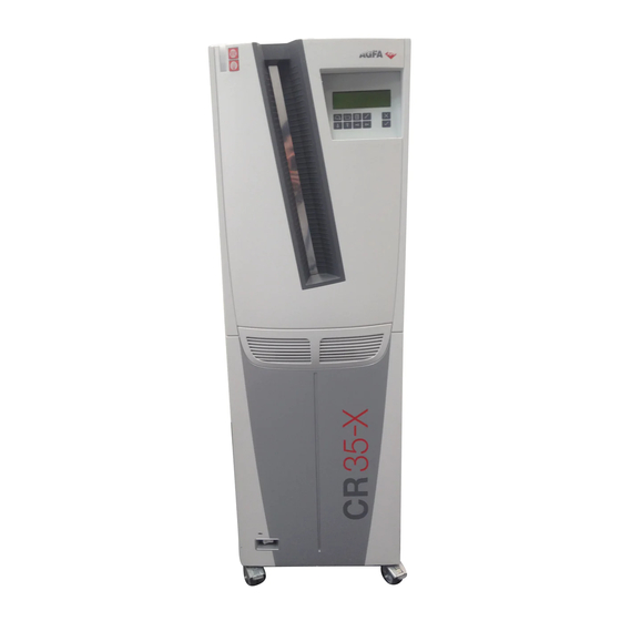
CR 35-X D IGITIZER CR 35-X features The CR 35-X is a Digitizer for image plates retaining latent X-ray images. It has been developed by Agfa. The CR 35-X accepts one cassette containing one image plate at a time. The ... -
Page 9: Warnings, Cautions And Notes
CR 35-X D IGITIZER Warnings, Cautions and Notes The following samples show how warnings, cautions, instructions and notes appear in this document. The text explains their intended use. WARNING: Warnings are directions which, if they are not followed, can cause serious or fatal injuries. -
Page 10: Equipment Classification
CR 35-X D IGITIZER Equipment Classification Class I Equipment Equipment in which protection against electric shock does not rely on basic insulation only, but includes a power sup- ply cord with protective earth conductor. For earth reli- ability always plug the main power cord into an earthed mains power outlet. -
Page 11: Training
IGITIZER Training The user must have received adequate Agfa training on the safe and effective use of the product before attempting to work with it. Training requirements may vary from country to country. The user should ensure that training is received in accordance with local laws or regulations that have the force of law. -
Page 12: Product Complaints
Agfa. If the device malfunctions and may have caused or contributed to a serious injury of a patient, Agfa must be notified immediately by telephone, fax or written correspondence to the following address: Agfa Service Support - local support addresses and phone numbers listed on www.agfa.com... -
Page 13: Safety Precautions
• Do not override or disconnect the integrated safety features. • As is the case for all technical devices, the CR 35-X must be operated, cared for and serviced correctly. • If you don’t operate the CR 35-X correctly or if you don’t have it serviced correctly, Agfa is not liable for resulting disturbances, damages or injuries. - Page 14 CR 35-X D IGITIZER • The classification of this product according to the medical electrical equipment standard IEC 60601-1 requires installation outside the patient vicinity. For definition of patient vicinity see dimensions below. Patient vicinity Patient vicinity R = 1.5 m/4.9 feet (EN 60601-1) or 1.83 m/6 feet (UL 60601-1).
- Page 15 Caution hot: Keep hands clear from the erasure unit. Supplementary protective earth connector: Provides a connection between the CR 35-X and the potential equalization busbar of the electrical system as found in medical environments. This plug should never be unplugged before the power is turned off and the power plug has been removed.
- Page 16 Insert the cassette in the input buffer as described in ‘Reading an image plate’ on page 43. At all times, keep your fingers clear of the input slot. As soon as the cassette enters the CR 35-X, release it. Safety precautions 4454C EN 2013-05-14...
- Page 17 12 mrad. Under normal operating conditions - when both doors are closed - there can be no laser radiation outside the CR 35-X. It is nonetheless imperative that the local radiation safety regulations regarding the protection of staff against scattered radiation are complied with, if the CR 35-X is located in the immediate vicinity of an X-ray room.
-
Page 18: Safety Compliance
IEC 60601-1-1 respectively IEC 60601-1:2005. If in doubt, consult your local service organization. Certificates The CR 35-X complies with: • the general safety standards: IEC 60601-1: 2005, EN 60601-1: 2006,... - Page 19 CR 35-X D IGITIZER Radio Interference Suppression It is hereby certified that the Digitizer has interference suppression according to the EN 55011 Class B as well as the FCC Rules CR47 Part 15 Class B (North- America). Short-range devices EN 300 330-2 V1.1.1 EN 301 489-03 V1.2.1...
-
Page 20: Operating Modes
CR 35-X D IGITIZER Operating modes The CR 35-X can be operated in three modes: operator mode, key-operator mode, and service mode. Operator mode The operator mode groups all basic functions which are aimed at radiographers: • Reading an image plate;... -
Page 21: Configurations
IGITIZER Configurations The CR 35-X can be used in two configurations: either one or more ID Stations serve a range of Digitizers, or one ID Station is dedicated to one Digitizer. For the ID Station a CR User Station with included ID Tablet can be used as well as a stand-alone ID Tablet. - Page 22 CR 35-X D IGITIZER CR 35-X ID Station with ID Tablet Interchangeable configuration Dedicated configuration If one ID Station is dedicated to one Digitizer, cassettes can be identified without using an ID Tablet. The identification data are transmitted from the ID Station to the Digitizer via the network.
- Page 23 CR 35-X ID Station without ID Tablet Dedicated configuration Note: In the dedicated configuration, you can still use the CR 35-X to digitize cassettes which have been identified on an ID Station or a CR User Station. 4454C EN 2013-05-14...
-
Page 24: Maintenance
Regular preventive maintenance needs to be done once per year or after 12000 cycles (whatever comes first). This maintenance cannot be done by the user but has to be done by an Agfa certified field service engineer. Not performing the regular maintenance by appropriately certified people can have impact on warranty commitments. - Page 25 CR 35-X D IGITIZER Cleaning and Disinfection All appropriate policies and procedures should be followed to avoid contamination of the staff, patients and device. All existing universal precautions should be taken to avoid that the digitizer comes into contact with potential contaminations. Details about cleaning can be found in the following pages.
- Page 26 Cleaning the optic unit is required if stripes parallel to the image plate movement can be seen in the image. When you recognize this type of artefact, when using the CR 35-X, clean the optic unit using the cleaning brush. Switch off the digitizer and disconnect from the mains.
- Page 27 CR 35-X D IGITIZER Hold the wire with two fingers near the housing and push it carefully towards the housing. Repeat this sequence until the head of the wire has reached the housing. Note: Misuse of the bowden wire leads to bending. This causes a complicated replacement f the dust brush.
-
Page 28: Patient Data Security
CR 35-X D IGITIZER Patient data security It is the responsibility of the hospital to ensure how the patients’ legal requirements are to be met, how the security of the patient records are: • maintained and tested, • audited, •... -
Page 29: Environmental Protection
For more detailed information about take-back and recycling of this product please contact your local Agfa service organization and/or Agfa dealer. By ensuring this product is disposed of correctly, you will help prevent potential negative consequences for the environment and human health, which could otherwise be caused by inappropriate waste handling of this product. -
Page 30: The User Interface
‘Survey of advanced functions (‘Key-operator mode’)’ page 64. For detailed information on the key-operator mode, refer to the CR 35-X Reference manual.An overview of the functions of the key-operator mode is given in ‘Survey of advanced functions (‘Key-operator mode’)’... - Page 31 CR 35-X D IGITIZER The keypad The CR 35-X keypad features the following keys: To give an image priority to be sent to the image processing Emergency station if other images are already waiting in the image queue. This key can only be used for unidentified cassettes.
- Page 32 • To toggle between values in a field. The display The CR 35-X control panel has a backlit LCD display with 8 lines of 40 characters each. Its lay-out depends on the operating mode. In operator mode, the display has dedicated areas for specific information: ...
- Page 33 During scanning of image plate and transmittal of image data; During transmittal of image data to image processing station. The operator main screen is: READY When the CR 35-X is treating an image plate, it displays the following screen: BUSY Miller Chest AP...
- Page 34 Informational messages are displayed as black text against a white background; warning messages are displayed in reverse mode. The status indicator The light at the top of the CR 35-X indicates the status of the CR 35-X. Constant/ Color Status...
- Page 35 Emergency buttons Two emergency buttons are located at the front of the CR 35-X. The emergency buttons determine the speed class, i.e. the sensitivity, which will be used to digitize the image plate. The sensitivity associated with the emergency buttons has been set during the configuration of your system.
- Page 36 A short beep means that CR 35-X has accepted the key command and is starting the operation. • A long beep means that you have pressed a non-active key or that the CR 35-X has rejected the key command. •...
-
Page 37: Switching On The Cr 35-X
CR 35-X D IGITIZER Switching on the CR 35-X Make sure that the setting of the voltage selector at the back of the machine matches the power supply voltage. Locate the main switch and place it in position ‘I’. 4454C EN 2013-05-14... - Page 38 WAIT Self test proceeding Note: During the self-test, you cannot activate any functions. If the CR 35-X has completed the self-test successfully, the CR 35-X enters the opera- tor mode and displays the operator main screen: READY Note: Notes provide advice and highlight unusual points. A note is not intended as an instruction.
-
Page 39: Switching Off The Cr 35-X
Switching off the CR 35-X Before switching off Check that the CR 35-X is not scanning an image plate. If the CR 35-X is scanning an image plate, the status indicator at the top of the machine is green and flashing. - Page 40 CR 35-X D IGITIZER Switching off the CR 35-X 4454C EN 2013-05-14...
-
Page 41: Chapter 2: Basic Operation ('Operator Mode')
Chapter Basic operation (‘Operator mode’) This chapter provides basic information on how to digitize image plates under normal conditions and in emergency situations. It also treats how to re-erase an image plate to prevent ghost images caused by previous exposures or by stray radiation. -
Page 42: Workflow
In the dedicated configuration the identification data are transmitted from the ID Station to the dedicated CR 35-X via the network. Therefore, the CR 35-X can digitize the image plate while you are entering the identification data on the ID Station. Refer to ‘Reading an image plate in the dedicated configuration’... -
Page 43: Reading An Image Plate
READY • The status indicator at the top of the CR 35-X must be green and be lit constantly. Note: The CR 35-X is operational if the status field equals ‘READY’, even if status messages of the destination are shown (e.g. ‘QS not ready’). - Page 44 • returns the cassette; • transmits the digital image data to the image processing station (‘destination’). When the CR 35-X has treated the cassette, it displays the operator main screen. Note: If the CR 35-X displays an error message, refer to ‘Troubleshooting...
- Page 45 READY • The status indicator at the top of the CR 35-X must be green and be lit constantly. Note: The CR 35-X is operational if the status field equals ‘READY’, even if status messages of the destination are shown (e.g. ‘QS not ready’).
- Page 46 Make sure to insert the cassette with the hinge [1] at the top and the locking mechanism [2] at the bottom. The CR 35-X starts digitizing the image plate. You can enter the identification data, refer to step 4. While treating the image plate, the CR 35-X will display the following screens:...
- Page 47 BUSY Miller Chest AP As soon as the CR 35-X has digitized the entire image plate and you have entered the identification data: • the CR 35-X erases the image plate and re-inserts it into the cassette; • the CR 35-X gives the cassette ID data the status ‘erased’.
-
Page 48: Reading An Emergency Image Plate
Make sure the cassette has been identified properly via the ID Station. Check that the CR 35-X is ready for operation: • The CR 35-X must display the operator main screen with ‘Ready’ status, e.g.: QS not ready READY Status field... - Page 49 IGITIZER • The status indicator at the top of the CR 35-X must be green and be lit constantly. Note: The CR 35-X is operational if the status field equals ‘READY’, even if status messages of the destination are shown (e.g. ‘QS not ready’).
- Page 50 Note: If you do not enter a cassette within 1 minute after pressing the Emergency key or if you enter a cassette without ID data, the CR 35-X will quit the emergency function and return to the operator main screen.
- Page 51 IGITIZER • The status indicator at the top of the CR 35-X must be green and be lit constantly. Note: The CR 35-X is operational if the status field equals ‘READY’, even if status messages of the destination are shown (e.g. ‘QS not ready’).
- Page 52 The image plate will be digitized using the speed class, i.e. the sensitivity, corre- sponding to the emergency button as defined during configuration. When the CR 35-X has treated the emergency image plate, it displays the operator digital image data main screen.
- Page 53 Status field • The status indicator at the top of the CR 35-X must be green and be lit constantly. Note: The CR 35-X is operational if the status field equals ‘READY’, even if status messages of the destination are shown (e.g. ‘QS not ready’).
- Page 54 Make sure to insert the cassette with the hinge [1] at the top and the locking mechanism [2] at the bottom. The CR 35-X starts digitizing the image plate. While treating the image plate, the CR 35-X will display the following screen: BUSY DIRECT ID...
- Page 55 [Examination type] equals ‘Extremities‘. • If you pressed the emergency button for digitizing images of the trunk, [Examination type] equals ‘Corpus’. When the CR 35-X has treated the emergency image plate, it displays the operator digital image data main screen. The are transmitted to the image processing station accompanied by default ID data.
-
Page 56: Re-Erasing An Image Plate
CR 35-X must display the operator main screen with ‘Ready’ status, e.g.: Status READY • the status indicator at the top of the CR 35-X must be green and be lit constantly. Press the Erase key on the keypad. Re-erasing an image plate 4454C EN 2013-05-14... - Page 57 Insert the cassette into the cassette slot. While erasing, the CR 35-X will still display the above screen. When the CR 35-X has erased the image plate, it displays the operator main screen. WARNING: If the above screen is not displayed but the display reads:...
- Page 58 READY Status • The status indicator at the top of the CR 35-X must be green and be lit constantly. Insert the cassette into the cassette slot. The CR 35-X will automatically erase the image plate. The display will read:...
-
Page 59: Reading The Identification Data Of A Cassette (Dedicated Configuration Only)
Status field • The status indicator at the top of the CR 35-X must be green and be lit constantly. Note: The CR 35-X is operational if the status field equals ‘READY’, even if status messages of the destination are shown (e.g. ‘QS not ready’). - Page 60 Make sure to insert the cassette with the hinge [1] at the top and the locking mechanism [2] at the bottom. While the CR 35-X reads the identification data from the cassette chip, the status indicator at the top of the machine is red and flashing.
-
Page 61: Changing The Image Plate Type (Dedicated Configuration Only)
Status field • The status indicator at the top of the CR 35-X must be green and be lit constantly. Note: The CR 35-X is operational if the status field equals ‘READY’, even if status messages of the destination are shown (e.g. ‘QS not ready’). - Page 62 Enter the initialization code in the ID Software. Refer to the User manual of the ID Software. While the CR 35-X initializes the cassette, the status indicator at the top of the machine is red and flashing. When the cassette has been initialized, the CR 35-X returns the cassette to the cas- sette slot and displays the operator main screen.
-
Page 63: Chapter 3: Advanced Operation ('Key-Operator Mode')
Chapter Advanced operation (‘Key-operator mode’) This chapter gives an overview of the key-operator functions and troubleshooting. For detailed information on these topics, refer to the Reference manual. Survey of advanced functions (‘Key-operator mode’) Troubleshooting checklist ... -
Page 64: Survey Of Advanced Functions ('Key-Operator Mode')
A survey of the functions which are available in key-operator mode is given below. For detailed information, refer to Chapter 3, ‘Advanced operation (‘Key- operator mode’)’ of the CR 35-X Reference manual. Function in key-operator main Section in Reference manual Page... -
Page 65: Troubleshooting Checklist
CR 35-X D IGITIZER Troubleshooting checklist A survey of possible problems is listed below. If corrective actions are straightforward, they are given below. The more elaborate troubleshooting procedures are explained in detail in Chapter 4, ‘Troubleshooting’ of the CR 35- X Reference manual. - Page 66 Reference manual. • Press Confirm key. English will be used. Default language is ERROR WHILE LOADING • Restart CR 35-X. LANGUAGE FILE used, please press • If the problem persists, contact your local service organization. Troubleshooting checklist 4454C EN 2013-05-14...
- Page 67 CR 35-X D IGITIZER Status field: WARNING MESSAGE 1 Message 2 Action • Press Confirm key. PARTLY SCANNED IP Possible loss of image, DETECTED press • Check image at destination. Status field: LOCKED MESSAGE 1 Message 2 Action • Press Confirm key.
- Page 68 (‘Queue management’)’ on page of the Reference manual. IMAGE-QUEUE FULL Check queue • Check that the CR 35-X is not off line (Refer to ‘The display’ page 32). • Press Confirm key. • Remove cassette. UNKNOWN DESTINATION Press , remove •...
- Page 69 CR 35-X D IGITIZER Errors when handling diskettes Error Action • Remove floppy. Wrong or missing volume label • Insert floppy with correct label. • Press Confirm key. • Remove floppy. Floppy not formatted • Insert formatted floppy. • Press Confirm key.
- Page 70 CR 35-X D IGITIZER Troubleshooting checklist 4454C EN 2013-05-14...
-
Page 71: Appendix A: Equipment Information Sheet
Appendix Equipment information sheet... - Page 72 IGITIZER Specifications Product description Type of product Digitizer Commercial name CR 35-X Model number 5158 Original seller/manufacturer Agfa HealthCare N.V. - Mortsel Labelling EN 60601-1:2006 EN 60601-2 EN 60825-1 NRTLus UL 60601-1 CSA 22.2 601-1 cNRTL CSA 22.2 601-2 Dimensions...
- Page 73 CR 35-X D IGITIZER Power consumption Standby • 230 V/ 50 Hz configuration 250 W • USA: 120 V/ 60 Hz configuration 250 W • Japan: 100 V/50 Hz and 100 V/60 Hz 250 W During operation • 230 V/ 50 Hz configuration max.
- Page 74 Preventive maintenance Preventive maintenance frequency Once a year or after 12000 cycles (whatever Note: Preventive maintenance needs to be done comes first). by an Agfa certified field service engineer. Grayscale resolution Data acquisition 12 bits/pixel Output to processor 12 bits/pixel...
- Page 75 CR 35-X D IGITIZER Spatial resolution HR: High resolution; SR: Standard resolution 35 x 43 cm (14 x 17") HR 10 pixels/mm 35 x 43 cm (14 x 17") SR 6,7 pixels/mm 21 x 43 cm HR 10 pixels/mm 35 x 35 cm (14 x 14") HR 10 pixels/mm 35 x 35 cm (14 x 14") SR...
- Page 76 CR 35-X D IGITIZER Scan area (scan width x scan length) HR: High resolution; SR: Standard resolution 35 x 43 cm (14 x 17") HR & SR 348 x 424 mm 21 x 43 cm HR 202 x 424 mm 35 x 35 cm (14 x 14") HR &...
-
Page 77: Appendix B: Cr Cassettes
Appendix CR cassettes... - Page 78 CR 35-X D IGITIZER Safety precautions Observe great care whenever removing the image plate from the CR cassette. Refer to the cleaning procedure described further on in this manual. WARNING: Make sure that the automatic exposure control device is placed above the cassette, to prevent patients from receiving an overdose of X-rays.
- Page 79 Embedded memory The main difference lies in the RF-tag memory chip that is permanently mounted in the cassette. Using the Agfa ID Software you can enter patient demographics and examination data into the memory chip. The identification of this data is performed by no-touch radiofrequency tagging via a built-in antenna card in the CR cassette.
- Page 80 CR 35-X D IGITIZER Image plate Another difference between a CR cassette and a conventional cassette is the X- ray sensitive element (image receptor). The latter is no longer a film, but an image plate that can be re-used thousands of times.
- Page 81 CR plate does not end up in a cassette initialized for another code. In case of doubt, you should re-initialize the cassette using the sensitivity code on the CR plate. Use only AGFA CR Phosphor Plate Cleaner and a soft lint-free cellulose cloth to clean the plate. WARNING: Do not use the AGFA CR Phosphor Plate Cleaner to clean the CR MM3.0 Mammo image plates with a batch code starting with...
- Page 82 CR 35-X D IGITIZER • More frequent cleaning is also required in case of excessive dust or under very dry conditions. (The screen cleaner contains antistatic agents which reduce buildup of static charges and dust collection.) Cleaning the image plate...
- Page 83 CR 35-X D IGITIZER Cleaning the cassettes Clean the cassette thoroughly. Use a dry cloth or blow away possible dust with compressed air. (DO NOT USE A SCREEN CLEANER TO CLEAN THE INSIDE OF THE CASSETTE.) 4454C EN 2013-05-14 Cleaning the cassettes...
- Page 84 CR 35-X D IGITIZER Technical specifications of the cassettes Sizes 35 x 43 cm (14 x 17"), 35 x 35 cm (14 x 14"), 24 x 30 cm, 18 x 24 cm, 8 x 10", ...
- Page 85 CR 35-X D IGITIZER Material BodyABS (Acrylonitryl Butadiene Styrene) CornersPolyurethane Rubber (PUR) HingePolypropylene (PP) Inner liningMakrolon Identification Memory chip (RF-tag card) embedded in the cassette Backscatter protection 150 µ lead 4454C EN 2013-05-14 Technical specifications of the cassettes...
- Page 86 Thanks to the red-shift of the stimulation spectrum, maximum stimulability is assured at 633 nm, the wavelength of the stimulating laser. The Agfa phosphor has excellent dark decay characteristics. Two hours after exposure, approximately 80% of the energy stored upon exposure is still...
- Page 87 CR 35-X D IGITIZER available. The image retention is greater than 50% up to 24 hours after irradiation. 4454C EN 2013-05-14 Technical specifications of the image plates...
- Page 88 CR 35-X D IGITIZER Technical specifications of the image plates 4454C EN 2013-05-14...
-
Page 89: Appendix C: Remarks For Hf-Emission And Immunity
Appendix Remarks for HF-emission and immunity... - Page 90 CR 35-X D IGITIZER Remarks for HF-emission and immunity This device is intended for operation in the electromagnetic environment given below. The user of the device should ensure that it is used in such an environment. Transmission Electromagnetic Environment Agreement...
- Page 91 CR 35-X D IGITIZER This device is intended for operation in the electromagnetic environment given below. The user of the device should ensure that it is used in such an environment. Resistance to IEC 60601 Level of Electromagnetic Environment Jamming Test...
- Page 92 CR 35-X D IGITIZER This device is intended for operation in the electromagnetic environment given below. The user of the device should ensure that it is used in such an environment. Tests of Resistance to IEC 60601 Level of Electromagnetic Environment...
- Page 93 CR 35-X D IGITIZER a. The field strength of stationary transmitters, such as base stations of radio telephones, mobile broadcasts for rural areas, amateur stations, and AM and FM radio transmitters, cannot be precisely predetermined theoreti- cally. An investigation of the location is recommended, to ascertain the electromagnetic environment as a result of stationary high frequency transmitters.
- Page 94 CR 35-X D IGITIZER This device is intended for operation in an electromagnetic environment in which the radiated high frequency disturbance variables are monitored. The user of the device can help to prevent electromagnetic disruptions by maintaining the minimum distances between portable and mobile high frequency...
- Page 95 CR 35-X D IGITIZER 4454C EN 2013-05-14 Remarks for HF-emission and immunity...
- Page 96 0413 Printed in Belgium Published by Agfa HealthCare N.V., B-2640 Mortsel-Belgium 4454C EN 2013-05-14...
Need help?
Do you have a question about the CR 35-X and is the answer not in the manual?
Questions and answers