Table of Contents
Advertisement
Quick Links
Advertisement
Table of Contents

Related Manuals for National Instruments PXIe-4162


Summary of Contents for National Instruments PXIe-4162
- Page 1 PXIe-4162 2022-07-06...
-
Page 2: Table Of Contents
Why Is the ACCESS LED Off When the Chassis Is On?..... . . 16 What Should I Do if the PXIe-4162 Fails the Self-Test?..... . 17 Where To Go Next. -
Page 3: Pxie-4162 Purpose And Introduction
PXIe-4162 PXIe-4162 Purpose and Introduction This document explains how to install, configure, and test the PXIe-4162. The PXIe-4162 ships with NI-DCPower driver software, which you can use to program the module. Note Before you begin, install and configure your chassis and controller. -
Page 4: Other Equipment
Store the module in the antistatic package when the module is not in use. Other Equipment There are several required items not included in your PXIe-4162 kit that you need to operate the PXIe-4162. Your application may require additional items not included in your kit to install or operate your PXIe-4162. -
Page 5: Installing The Software
Installing the Software You must be an Administrator to install NI software on your computer. 1. Install an ADE, such as LabVIEW or LabWindows™/CVI™. 2. Visit ni.com/downloads/drivers and search for NI-DCPower. © National Instruments... -
Page 6: Installing The Pxie-4162
PXIe-4162 3. Download the latest version of NI-DCPower by clicking Download and then running the executable (.exe) file. Driver support for the PXIe-4162 was first available in NI-DCPower 17.6. 4. Follow the instructions in the installation prompts. Note Windows users may see access and security messages during installation. - Page 7 12. Cover all empty slots using EMC filler panels or fill using slot blockers to maximize cooling air flow, depending on your application. 13. Power on the chassis. Related tasks Why Is the ACCESS LED Off When the Chassis Is On? ■ © National Instruments...
-
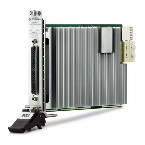
Page 8: Pxie-4162 Pinout And Leds
PXIe-4162 PXIe-4162 Pinout and LEDs Front Panel Refer to the following figures and tables for information about the PXIe-4162 front panel connector pins, channels, and LEDs. PXIe-4162 12-CH Precision SMU ACCES S VOLTAGE OUTPUT ALL CHANNEL SIGNALS ± 24V MAX... - Page 9 Refer to the driver software for possible sources. The device will not operate until the error is cleared and/or the device is reset. Table 2. LED Voltage Status Indicator Pinout The following figure and table provide detailed signal information for the PXIe-4162 connector. Calibration HI CH0 Guard...
- Page 10 PXIe-4162 Bundle Channel Pin Signal Description 41 Sense LO Guard#GUID-0B3D8A7D-C725-4D31- A90A-3B6C1E4E3A23__GUARDTERMINALS 20 Output HI 19 Sense HI 17 Sense LO Guard#GUID-0B3D8A7D-C725-4D31- A90A-3B6C1E4E3A23__GUARDTERMINALS 39 Output HI 38 Sense HI 59 Sense LO Guard#GUID-0B3D8A7D-C725-4D31- A90A-3B6C1E4E3A23__GUARDTERMINALS 57 Output HI 56 Sense HI 36 Sense LO...
- Page 11 Output HI Sense HI Sense LO Guard#GUID-0B3D8A7D-C725-4D31- A90A-3B6C1E4E3A23__GUARDTERMINALS 23 Output HI 22 Sense HI 43 Sense LO Guard#GUID-0B3D8A7D-C725-4D31- A90A-3B6C1E4E3A23__GUARDTERMINALS A, B, C, D 0 to 11 10 Output LO — — 21 Calibration HI 24 Not used Void © National Instruments...
- Page 12 Channel Pin Signal Description Table 3. PXIe-4162 Signal Descriptions Cable Bundles The PXIe-4162 has 12 channels organized into four cable bundles (A, B, C, D) for use with associated cable accessories. The following figure and table provide detailed bundle information.
-
Page 13: Configuring The Pxie-4162 In Max
Self-Calibrating the PXIe-4162 Self-calibration adjusts the PXIe-4162 for variations in the module environment. Perform a complete self-calibration after the first time you install the PXIe-4162. 1. Install the PXIe-4162 and let it warm up for 30 minutes. © National Instruments... -
Page 14: Programming The Pxie-4162
After first installing the PXIe-4162 in a chassis ■ After any module that is in the same chassis as the PXIe-4162 is installed, ■ uninstalled, or moved When the PXIe-4162 is in an environment where the ambient temperature ■... - Page 15 LabWindows/CVI—Available at Program Files » IVI Foundation » IVI » Drivers » NI-DCPower. LabWindows/CVI examples are available from the Start menu in the National Instruments folder. C/C++—Available at Program Files » IVI Foundation » IVI. Refer to the Creating an...
-
Page 16: Troubleshooting
If an issue persists after you complete a troubleshooting procedure, contact NI technical support or visit ni.com/support. What Should I Do if the PXIe-4162 Doesn't Appear in MAX? 1. In the MAX configuration tree, expand Devices and Interfaces. 2. Expand the Chassis tree to see the list of installed hardware, and press <F5> to refresh the list. -
Page 17: What Should I Do If The Pxie-4162 Fails The Self-Test
PXIe-4162 Notice Apply external signals only while the PXIe-4162 is powered on. Applying external signals while the module is powered off may cause damage. 1. Disconnect any signals from the module front panels. 2. Power off the chassis. 3. Remove the module from the chassis and inspect it for damage. Do not reinstall a damaged module. -
Page 18: Where To Go Next
(ADE) or review device an application programming for your application. specifications. interface (API). Getting Started PXIe-4162 Specifications* NI-DCPower Soft Front Panel NI-DCPower Instrument Driver with LabVIEW NI DC Power Supplies NI-DCPower Examples* Getting Started with and SMUs Help*... - Page 19 1 866 ASK MYNI (275 6964). For support outside the United States, visit the Worldwide Offices section of ni.com/niglobal to access the branch office websites, which provide up- to-date contact information. © National Instruments © 2022 National Instruments Corporation.
Need help?
Do you have a question about the PXIe-4162 and is the answer not in the manual?
Questions and answers