Table of Contents
Advertisement
Quick Links
Advertisement
Table of Contents

Subscribe to Our Youtube Channel
Related Manuals for Arcteq AQ-C215


Summary of Contents for Arcteq AQ-C215
- Page 1 AQ-C215 Capacitor bank protection IED Instruction manual...
-
Page 3: Table Of Contents
4.9 Configuring user levels and their passwords................. 50 5 Functions unctions ...................................................... 53 5.1 Functions included in AQ-C215 ................... 53 5.2 Measurements........................54 5.2.1 Current measurement and scaling ................54 5.2.2 Voltage measurement and scaling ................67 5.2.3 Power and energy calculation ..................78 5.2.4 Frequency tracking and scaling ................. - Page 4 7 Connections and applic 7 Connections and applica a tion examples tion examples..................................286 7.1 Connections of AQ-C215 ....................286 7.2 Application example and its connections................288 7.3 Two-phase, three-wire ARON input connection ..............290 7.4 Trip circuit supervision (95) ....................291...
- Page 5 9.3 Tests and environmental ....................342 10 Or 10 Ordering inf dering informa ormation tion ............................................345 11 Contact and r 11 Contact and re e f f er erence inf ence informa ormation tion....................................347 © Arcteq Relays Ltd IM00040...
- Page 6 Nothing contained in this document shall increase the liability or extend the warranty obligations of the manufacturer Arcteq Relays Ltd. The manufacturer expressly disclaims any and all liability for any damages and/or losses caused due to a failure to comply with the instructions contained herein or caused by persons who do not fulfil the aforementioned requirements.
- Page 7 A A Q Q -C215 -C215 Instruction manual Version: 2.07 Copyright Copyright © Arcteq Relays Ltd. 2022. All rights reserved. © Arcteq Relays Ltd IM00040...
-
Page 8: Document Inf
Revision 2.01 Date 6.11.2019 - First revision of AQ-C215. - Added description for LED test and button test. - Complete rewrite of every chapter. Changes - Improvements to many drawings and formula images. - Page 9 - Improvements to many drawings and formula images. - Improved and updated IED user interface display images. - AQ-C215 Functions included list Added: Capacitor bank protection module, capacitor bank overload protection, voltage memory and programmable stage. - Added 6th harmonic to harmonic overcurrent protection function.
- Page 10 GOOSE inputs. - Added function block diagram. - Arc point sensor HSO1 and HSO2 position fixed. - Added spare part codes and compatibilities to option cards. Revision 2.07 Date 7.7.2022 Changes - Added THD voltage measurements. © Arcteq Relays Ltd IM00040...
-
Page 11: Abbr Bbre E Via Viations Tions
FFT – Fast Fourier transform FTP – File Transfer Protocol GI – General interrogation HMI – Human-machine interface HR – Holding register HV – High voltage HW – Hardware IDMT– Inverse definite minimum time IED – Intelligent electronic device © Arcteq Relays Ltd IM00040... - Page 12 SG – Setting group SOTF – Switch-on-to-fault SW – Software THD – Total harmonic distortion TRMS – True root mean square VT – Voltage transformer VTM – Voltage transformer module VTS – Voltage transformer supervision © Arcteq Relays Ltd IM00040...
-
Page 13: General
It includes capacitor bank current unbalance and overload protection in addition to standard overcurrent, earth fault and voltage protections. The AQ-C215 capacitor bank protection IED is a member of the AQ-200 product line. The hardware and software are modular: the hardware modules are assembled and configured according to the application's I/O requirements, and the software determines the available functions. -
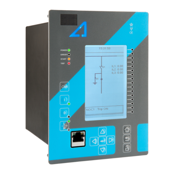
Page 14: Ied User Interface Erface
(hardware or software) error that affects the operation of the unit. The activation of the yellow "Start" LED and the red "Trip" LED are based on the setting the user has put in place in the software. © Arcteq Relays Ltd IM00040... -
Page 15: Mimic And Main Menu
) takes you to the password menu where you can enter the passwords for the various user levels (User, Operator, Configurator, and Super-user). 4.2.2 Navigation in the main configuration menus All the settings in this device have been divided into the following six (6) main configuration menus: • General • Protection © Arcteq Relays Ltd IM00040... -
Page 16: General Menu
The General main menu is divided into two submenus: the Device info tab presents the information of the device, while the Function comments tab allows you to view all comments you have added to the functions. Figure. 4.3 - 4. General menu structure © Arcteq Relays Ltd IM00040... - Page 17 Info page with the Force status to parameter. System phase rotating 0: A-B-C Allows the user to switch the expected order in which 0: A-B-C order 1: A-C-B the phase measurements are wired to the unit. © Arcteq Relays Ltd IM00040...
- Page 18 Displays the status of all enabled functions. Monitor profile Function comments Function comments displays notes of each function that has been activated in the Protection, Control and Monitoring menu. Function notes can be edited by the user. © Arcteq Relays Ltd IM00040...
-
Page 19: Protection Menu
The Protection main menu includes the Stage activation submenu as well as the submenus for all the various protection functions, categorized under the following modules: "Arc protection", "Current", "Voltage", "Frequency", "Sequence" and "Supporting" (see the image below). The available functions depend on the device type in use. © Arcteq Relays Ltd IM00040... - Page 20 For example, the I> (overcurrent) protection stage can be found in the "Current" module, whereas the U< (undervoltage) protection stage can be found in the "Voltage" module. Figure. 4.4 - 9. Submenus for Stage activation. © Arcteq Relays Ltd IM00040...
- Page 21 Each protection stage and supporting function has five sections in their stage submenus: "Info", "Settings", " Registers", "I/O" and "Events". Figure. 4.4 - 11. Info. The "Info" section offers many details concerning the function and its status: © Arcteq Relays Ltd IM00040...
- Page 22 Voltage and current transformers nominal values can be set at Measurement → Transformers . • Delay type and operating time delay settings are described in detail in chapter General properties of a protection function . © Arcteq Relays Ltd IM00040...
- Page 23 Data included in the register depend on the protection function. You can clear the the operation register by choosing "Clear registers" → "Clear". "General event register" stores the event generated by the stage. These general event registers cannot be cleared. © Arcteq Relays Ltd IM00040...
- Page 24 "Blocking input control" allows you to block stages. The blocking can be done by using any of the following: • digital inputs • logical inputs or outputs • the START, TRIP or BLOCKED information of another protection stage • object status information. © Arcteq Relays Ltd IM00040...
-
Page 25: Control Menu
, for configuring the objects ( Objects) , for setting the various control functions ( Control functions) , and for configuring the inputs and outputs ( Device I/O) . The available control functions depend on the model of the device in use. © Arcteq Relays Ltd IM00040... - Page 26 Force SG change enable must be "Enabled"). • Used se Used set t ting gr ting groups oups: this setting allows the activation of setting groups SG1...SG8 (only one group is active by default). © Arcteq Relays Ltd IM00040...
- Page 27 Each activated object is visible in the Objects submenu. By default all objects are disabled unless specifically activated in the Controls → Controls enabled submenu. Each active object has four sections in their submenus: "Settings", "Application control" ("App contr"), "Registers" and "Events". These are described in further detail below. © Arcteq Relays Ltd IM00040...
- Page 28 A request is considered to have failed when the object does not change its status as a result of that request. • C C lear sta lear statistics tistics: statistics can be cleared by choosing "Clear statistics" and then "Clear". © Arcteq Relays Ltd IM00040...
- Page 29 MIMIC (each level has its own password). By default, the access level is set to "Configurator". • You can use digital inputs to control the object locally or remotely. Remote controlling via the bus is configured on the protocol level. © Arcteq Relays Ltd IM00040...
- Page 30 Object blocking is done in the "Blocking input control" subsection. It can be done by any of the following: digital inputs, logical inputs or outputs, object status information as well as stage starts, trips or blocks. Figure. 4.5 - 22. Registers section. © Arcteq Relays Ltd IM00040...
- Page 31 In the image series below, the user has activated three control functions. The user accesses the list of activated control stages through the "Control functions" module, and selects the control function for further inspection. Figure. 4.5 - 24. Control functions submenu. © Arcteq Relays Ltd IM00040...
- Page 32 While the function is activated and disabled in the Control → Controls enabled submenu, you can disable the function through the "Info" section (the [function name] mode at the top of the section). Figure. 4.5 - 26. Settings section. © Arcteq Relays Ltd IM00040...
- Page 33 Data included in the register depend on the control function. You can clear the the operation register by choosing "Clear registers" → "Clear". "General event register" stores the event generated by the stage. These general event registers cannot be cleared. © Arcteq Relays Ltd IM00040...
- Page 34 "Blocking input control" allows you to block stages. The blocking can be done by using any of the following: • digital inputs. • logical inputs or outputs. • the START, TRIP or BLOCKED information of another protection stage. • object status information. © Arcteq Relays Ltd IM00040...
- Page 35 Mimic Indicator", "Logic signals" and "GOOSE matrix". Please note that digital inputs, logic outputs, protection stage status signals (START, TRIP, BLOCKED, etc.) as well as object status signals can be connected to an output relay or to LEDs in the "Device I/O matrix" section. © Arcteq Relays Ltd IM00040...
- Page 36 "Event masks" subsection you can determine which events are masked –and therefore recorded into the event history– and which are not. Figure. 4.5 - 32. Digital outputs section. All settings related to digital outputs can be found in the "Digital outputs" section. © Arcteq Relays Ltd IM00040...
- Page 37 LED quick displays and the matrices. You can also modify the color of the LED ("LED color settings") between green and yellow; by default all LEDs are green. © Arcteq Relays Ltd IM00040...
- Page 38 These signals can be used in a variety of situations, such as for controlling the logic program, for function blocking, etc. You can name each switch and set the access level to determine who can control the switch. © Arcteq Relays Ltd IM00040...
- Page 39 Logical output signals can be used as the end result of a logic that has been built in the AQtivate setting tool. The end result can then be connected to a digital output or a LED in the matrix, block functions and much more. © Arcteq Relays Ltd IM00040...
-
Page 40: Communication Menu
IP address of your device (can be found in the Communication → Connections submenu). As a standard, the devices support the following communication protocols: NTP, IEC 61850, Modbus/TCP, Modbus/RTU, IEC 103, IEC 101/104, SPA, DNP3 and Modbus/IO. © Arcteq Relays Ltd IM00040... - Page 41 When communicating with a device through a front Ethernet port connection, the IP address is always 192.168.66.9. SERIAL COM1 & COM2 SERIAL COM1 & COM2 SERIAL COM1 and SERIAL COM2 are reserved for serial communication option cards. They have the same settings as RS-485 port. © Arcteq Relays Ltd IM00040...
- Page 42 • DNP3: Supports serial and Ethernet communication. • ModbusIO: Used for connecting external devices like ADAM RTD measurement units. NOTE! Please refer to the "System integration" chapter for a more detailed text on the various communication options. © Arcteq Relays Ltd IM00040...
-
Page 43: Measurement Menu
Transformers menu is used for setting up the measurement settings of available current transformer modules or voltage transformer modules. Some unit types have more than one CT or VT module. Some unit types like AQ-S214 do not have current or voltage transformers at all. © Arcteq Relays Ltd IM00040... - Page 44 U4 channel can be set to work as residual voltage mode or "SS" (system set) mode, which can be used for synchrochecking, synchronizing and other uses. © Arcteq Relays Ltd IM00040...
- Page 45 Ref1, fRef2 and fRef3. With these parameters it is possible to set up three voltage or current channels to be used for frequency sampling. Parameter "f.meas in use" indicates which of the three channels are used for sampling if any. © Arcteq Relays Ltd IM00040...
- Page 46 (IL1, IL2, IL3) as well as the two residual currents (I01, I02); each component can be displayed as absolute or percentage values, and as primary or secondary amperages or in per-unit values. © Arcteq Relays Ltd IM00040...
- Page 47 • "Harmonics" displays harmonics up to the 31 harmonic for all four voltages (U1, U2, U3, U4); each component can be displayed as absolute or percentage values, and as primary or secondary voltages or in per-unit values. © Arcteq Relays Ltd IM00040...
- Page 48 "Energy measurements" displays the three-phase energy as well as the energies of the individual phases. Impedance calculations Figure. 4.7 - 48. Impedance calculations submenu. © Arcteq Relays Ltd IM00040...
-
Page 49: Monitoring Menu
( Disturbance REC ) and accessing the device diagnostics ( Device diagnostics ). The available monitoring functions depend on the type of the device in use. Figure. 4.8 - 50. Monitoring menu view. © Arcteq Relays Ltd IM00040... - Page 50 Configuring monitor functions is very similar to configuring protection and control stages. They, too, have the five sections that display information ("Info"), set the parameters ("Settings"), show the inputs and outputs ("I/O") and present the events and registers ("Events" and "Registers"). © Arcteq Relays Ltd IM00040...
- Page 51 • "Pretriggering time" can be selected between 0.1…15.0 s. • The IED can record up to 20 (20) analog channels that can be selected from the twenty (20) available channels. Every measured current or voltage signal can be selected to be recorded. © Arcteq Relays Ltd IM00040...
-
Page 52: Configuring User Levels And Their Passwords
A number of stars are displayed in the upper right corner of the HMI; these indicate the current user level. The different user levels and their star indicators are as follows (also, see the image below for the HMI view): © Arcteq Relays Ltd IM00040... - Page 53 • User: Can view any menus and settings but cannot change any settings, nor operate breakers or other equipment. • Operator: Can view any menus and settings but cannot change any settings BUT can operate breakers and other equipment. © Arcteq Relays Ltd IM00040...
- Page 54 • Super user: Can change any setting and can operate breakers and other equipment. NOTE! Any user level with a password automatically locks itself after half an hour (30 minutes) of inactivity. © Arcteq Relays Ltd IM00040...
-
Page 55: Functions Unctions
Instruction manual Version: 2.07 5 Functions 5.1 Functions included in AQ-C215 The AQ-C215 capacitor bank protection IED includes the following functions as well as the number of stages for those functions. Table. 5.1 - 3. Protection functions of AQ-C215. Name (number... -
Page 56: Measurements
A A Q Q -C215 -C215 Instruction manual Version: 2.07 Table. 5.1 - 4. Control functions of AQ-C215. Name ANSI Description Setting group selection Object control and monitoring (5 objects available) SOTF SOTF Switch-on-to-fault Table. 5.1 - 5. Monitoring functions of AQ-C215. - Page 57 For the measurements to be correct the user needs to ensure that the measurement signals are connected to the correct inputs, that the current direction is connected to the correct polarity, and that the scaling is set according to the nominal values of the current transformer. © Arcteq Relays Ltd IM00040...
- Page 58 CT in Input I02 T in Input I02 L L oad ( oad (nominal) nominal) - CT primary: 100 A - I0CT primary: 10 A 36 A - CT secondary: 5 A - I0CT secondary: 1 A © Arcteq Relays Ltd IM00040...
- Page 59 If the protected object's nominal current is chosen to be the basis for the per-unit scaling, the option "Object in p.u." is selected for the "Scale meas to In" setting (see the image below). Figure. 5.2.1 - 58. Setting the phase current transformer scalings to the protected object's nominal current. © Arcteq Relays Ltd IM00040...
- Page 60 The first of the two images shows how the measurements are displayed when the CT primary values are the basis for the scaling; the second shows them when the protected object's nominal current is the basis for the scaling. © Arcteq Relays Ltd IM00040...
- Page 61 Zero sequence CT scaling (ZCT scaling) is done when a zero sequence CT instead of a ring core CT is part of the measurement connection. In such a case the zero sequence CT should be connected to the I02 channel which has lower CT scaling ranges (see the image below). © Arcteq Relays Ltd IM00040...
- Page 62 The measured current amplitude does not match one of the measured phases./ Check the wiring connections between the injection device or the CTs and the relay. The calculated I0 is measured even though it should not. © Arcteq Relays Ltd IM00040...
- Page 63 The following image presents the most common problems with phase polarity. Problems with phase polarity are easy to find because the vector diagram points towards the opposite polarity when a phase has been incorrectly connected. © Arcteq Relays Ltd IM00040...
- Page 64 If two phases are mixed together, the network rotation always follows the pattern IL1-IL3-IL2 and the measured negative sequence current is therefore always 1.00 (in. p.u.). © Arcteq Relays Ltd IM00040...
- Page 65 "Scale measurement to In" setting. Ipu scaling A relay feedback value; the scaling factor for the primary current's primary per-unit value. Ipu scaling A relay feedback value; the scaling factor for the secondary current's secondary per-unit value. © Arcteq Relays Ltd IM00040...
- Page 66 The primary RMS current measurement from each of the phase current ILx 0.00…1000000.00 0.01 current channels. ("Pri.Pha.curr.ILx") Primary phase current ILx TRMS The primary TRMS current (inc. harmonics up to 31 0.00…1000000.00 0.01 ("Pha.curr.ILx measurement from each of the phase current channels. TRMS Pri") © Arcteq Relays Ltd IM00040...
- Page 67 The secondary RMS current measurement from the residual current current I0x 0.00…300.00 0.01 channel I01 or I02. ("Sec.Res.curr.I0x") Secondary The secondary RMS current measurement from the calculated current calculated I0 0.00…300.00 0.01 channel I0. ("Sec.calc.I0") © Arcteq Relays Ltd IM00040...
- Page 68 Secondary negative sequence current The secondary measurement from the calculated negative 0.00…300.00 0.01 ("Sec.Negative sequence sequence current. curr") Secondary zero sequence The secondary measurement from the calculated zero current 0.00…300.00 0.01 sequence current. ("Sec.Zero sequence curr.") © Arcteq Relays Ltd IM00040...
-
Page 69: Voltage Measurement And Scaling
The measured values are processed into the measurement database and they are used by measurement and protection functions (the protection function availability depends of the relay type). It is essential to understand the concept of voltage measurements to be able to get correct measurements. © Arcteq Relays Ltd IM00040... - Page 70 VT ratings. In the figure below, three line-to-neutral voltages are connected along with the zero sequence voltage; therefore, the 3LN+U4 mode must be selected and the U4 channel must be set as U0. Other possible connections are presented later in this chapter. © Arcteq Relays Ltd IM00040...
- Page 71 ( Protection → Voltage → [protection stage menu] → INFO ; see the image below). The number of available protection functions depends on the relay type. Figure. 5.2.2 - 68. Selecting the measured magnitude. © Arcteq Relays Ltd IM00040...
- Page 72 • 2LL+U3+U4 (two line-to-line voltages and the U3 and the U4 channels can be used for synchrochecking, zero sequence voltage, or for both) The 3LN+U0 is the most common voltage measurement mode. See below for example connections of voltage line-to-line measurement (3LL on the left, 2LL on the right). © Arcteq Relays Ltd IM00040...
- Page 73 The measurement mode is 3LN+U4 which means that the relay is measuring line-to-neutral voltages. The VT scaling has been set to 20 000 : 100 V. The U4 channel measures the zero sequence voltage which has the same ratio (20 000 : 100 V). © Arcteq Relays Ltd IM00040...
- Page 74 The measured voltage amplitude does not match one of the measured phases./ Check the wiring connections between the injection device or the VTs and the relay. The calculated U0 is measured even though it should not. © Arcteq Relays Ltd IM00040...
- Page 75 "2LL+U3+U4" mode is selected. U3 Res/SS VT The secondary nominal voltage of the connected U0 or SS VT. This 0.2…400V 0.1V 100.0V secondary setting is only valid if the "2LL+U3+U4" mode is selected. © Arcteq Relays Ltd IM00040...
- Page 76 The following measurements are available in the measured voltage channels. Table. 5.2.2 - 25. Per-unit voltage measurements. Name Unit Range Step Description Voltage Ux × U 0.00…500.0 0.01 The RMS voltage measurement (in p.u.) from each of the voltage channels. ("UxVolt p.u.") © Arcteq Relays Ltd IM00040...
- Page 77 Range Step Description Secondary positive sequence The secondary measurement from the calculated positive voltage 0.00…4800.0 0.01 sequence voltage. ("Pos.seq.Volt.sec") Secondary negative sequence The secondary measurement from the calculated negative voltage 0.00…4800.0 0.01 sequence voltage. ("Neg.seq.Volt.sec") © Arcteq Relays Ltd IM00040...
- Page 78 ("System volt UL2 mag") System voltage magnitude The primary RMS line-to-neutral UL3 voltage (measured or calculated). You 0.00…1000000.00 0.01 can also select the row where the unit for this is kV. ("System volt UL3 mag") © Arcteq Relays Ltd IM00040...
- Page 79 System voltage angle 0.00…360.0 0.01 The primary line-to-neutral angle UL3 (measured or calculated). ("System volt UL3 ang") System voltage angle 0.00…360.0 0.01 The primary zero sequence angle U0 (measured or calculated). ("System volt U0 ang") © Arcteq Relays Ltd IM00040...
-
Page 80: Power And Energy Calculation
The following equations apply for power calculations with the line-to-neutral mode and the line- to-line voltage mode (with U0 connected and measured): © Arcteq Relays Ltd IM00040... - Page 81 The direction of reactive power is divided into four quadrants. Reactive power may be inductive or capacitive on both forward and reverse directions. Reactive power quadrant can be indicated with Tan (φ) (tangent phi), which is calculated according the following formula: © Arcteq Relays Ltd IM00040...
- Page 82 (i.e. wiring errors, wrong measurement modes, faulty frequency settings, etc.). Settings Table. 5.2.3 - 35. Power and energy measurement settings Name Range Step Default Description 3ph active 0: Disabled energy Enables/disables the active energy measurement. 1: Enabled Disabled measurement © Arcteq Relays Ltd IM00040...
- Page 83 Clear pulse 0: - Resets the "DC 1…4 Pulses sent" counters back to 0: - counter 1: Clear zero. DC 1…4 0: Disabled Enables/disables the energy dose counter 1…4 0: Disabled enable 1: Enabled individually. © Arcteq Relays Ltd IM00040...
- Page 84 Name Unit Range Step Description Lx Apparent power (S) 0.01 The apparent power of Phase Lx in kilo-volt-amperes -1x10 …1x10 Lx Active power (P) 0.01 The active power of Phase Lx in kilowatts -1x10 …1x10 © Arcteq Relays Ltd IM00040...
- Page 85 (P) (kVAh or MVAh) active energy is imported. 904.00 Table. 5.2.3 - 41. Single-phase energy calculations (L1...L3). Name Range Step Description Export Active Energy Lx (kWh or MWh) 0.01 The exported active energy of the phase. -1x10 …1x10 © Arcteq Relays Ltd IM00040...
- Page 86 1000 : 5 A. Voltages (line-to-neutral): Currents: = 40.825 V, 45.00° = 2.5 A, 0.00° = 61.481 V, -159.90° = 2.5 A, -120.00° = 97.742 V, 126.21° = 2.5 A, 120.00° © Arcteq Relays Ltd IM00040...
- Page 87 = 2.5 A, 0.00° = 100.00 V, -90.00° = 2.5 A, -120.00° = 2.5 A, 120.00° Name Values 3PH (S) 20.00 MVA 3PH (P) 17.32 MW 3PH (Q) 0.00 Mvar 3PH Tan 0.00 3PH Cos 0.87 © Arcteq Relays Ltd IM00040...
-
Page 88: Frequency Tracking And Scaling
FFT calculation always has a whole power cycle in the buffer. The measurement accuracy is further improved by Arcteq's patented calibration algorithms that calibrate the analog channels against eight (8) system frequency points for both magnitude and angle. - Page 89 0: Use track 0: Use Defines the start of the sampling. Sampling can begin with Start sampling frequency track a previously tracked frequency, or with a user-set nominal with 1: Use nom frequency frequency. frequency © Arcteq Relays Ltd IM00040...
-
Page 90: General Menu
Protection , Control and Monitor profiles. Table. 5.3 - 44. Parameters and indications in the General menu. Name Range Default Description The file name uses these fields when loading the .aqs configuration file Device name Unitname from the AQ-200 unit. © Arcteq Relays Ltd IM00040... - Page 91 The unique serial number identification of the unit. Firmware version The firmware software version of the unit. Hardware configuration The order code identification of the unit. UTC time The UTC time value which the device's clock uses. © Arcteq Relays Ltd IM00040...
-
Page 92: Protection Functions
The protection function is run in a completely digital environment with a protection CPU microprocessor which also processes the analog signals transformed into the digital form. © Arcteq Relays Ltd IM00040... - Page 93 Figure. 5.4.1 - 78. Pick up and reset. The pick-up activation of the function is not directly equal to the START signal generation of the function. The START signal is allowed if a blocking condition is not active. © Arcteq Relays Ltd IM00040...
- Page 94 • Definite time operation (DT): activates the trip signal after a user-defined time delay regardless of the measured current as long as the current is above or below the X value and thus the pick-up element is active (independent time characteristics). © Arcteq Relays Ltd IM00040...
- Page 95 Selects whether the delay curve series for an IDMT operation follows either IEC or IEEE/ANSI standard defined characteristics. Delay curve 0: IEC 0: IEC series 1: IEEE This setting is active and visible when the "Delay type" parameter is set to "IDMT". © Arcteq Relays Ltd IM00040...
- Page 96 "Param". Defines the Constant C for IEEE characteristics. This setting is active and visible when the "Delay type" parameter is 0.0000…250.0000 0.0001 0.0200 set to "IDMT" and the "Delay characteristic" parameter is set to "Param". © Arcteq Relays Ltd IM00040...
- Page 97 = Operating delay (s) t = Operating delay (s) k = Time dial setting k = Time dial setting = Measured maximum current = Measured maximum current = Pick-up setting = Pick-up setting © Arcteq Relays Ltd IM00040...
- Page 98 1: Yes reset. release time The behavior of the stages with different release time configurations are presented in the figures below. Figure. 5.4.1 - 82. No delayed pick-up release. © Arcteq Relays Ltd IM00040...
- Page 99 -C215 Instruction manual Version: 2.07 Figure. 5.4.1 - 83. Delayed pick-up release, delay counter is reset at signal drop-off. Figure. 5.4.1 - 84. Delayed pick-up release, delay counter value is held during the release time. © Arcteq Relays Ltd IM00040...
-
Page 100: Capacitor Bank Module
Capacitor banks are commonly used to improve the quality of the electrical supply and the efficient operation of the power system. The main purpose of the installation is to provide capacitive compensations and power factor corrections. © Arcteq Relays Ltd IM00040... - Page 101 When the wye is earthed, it provides a low-impedance path to earth. An earthed, wye-connected capacitor bank has the following advantages: • A low-impedance path to earth provides inherent self-protection against lightning surge currents and give some protection against surge voltages. © Arcteq Relays Ltd IM00040...
- Page 102 Unbalance protection should have a minimum intentional delay to minimize the amount of damage done to the bank in the event of external arcing. © Arcteq Relays Ltd IM00040...
- Page 103 Longer delays increase the probability of bank failures. © Arcteq Relays Ltd IM00040...
-
Page 104: Capacitor Bank Overload Protection (Icol>; 49Ol)
START and TRIP events simultaneously with an equivalent time stamp. The time stamp resolution is 1 ms. The function also provides a resettable cumulative counter for the START, TRIP and BLOCKED events. The following figure presents a simplified function block diagram of the capacitor bank overload function. © Arcteq Relays Ltd IM00040... - Page 105 20 ms averaged history value from -20 ms from START or TRIP event. General settings The following general settings define the general behavior of the function. These settings are static i.e. it is not possible to change them by editing the setting group. © Arcteq Relays Ltd IM00040...
- Page 106 When the function has detected a fault and counts down time towards a trip, remaining 0.000...1800.000s 0.005s this displays how much time is left before tripping occurs. to trip meas 0.00...1250.00 0.01 The ratio between the highest measured phase current and the pick-up value. at the moment © Arcteq Relays Ltd IM00040...
- Page 107 Defines the IDMT constant A. Note that this setting is only visible IDMT Const A 0.01...25.00 0.01 1.00 when the "Point 1(9)–2(10) characteristics" setting is set to "Two 1(9) – 2(10) point steps" or "Two point interpolate". © Arcteq Relays Ltd IM00040...
- Page 108 = 3.0…5.0, definite time step, the set 3.0 s is held until the I ratio meas meas reaches 5.0, and after that the time point = 4 is used with the time setting 0.1 s. © Arcteq Relays Ltd IM00040...
-
Page 109: Capacitor Bank Current Unbalance Protection (Iuc>; 46C)
The function can operate on instant or time-delayed mode. The function includes CT saturation checking which allows the function to start and operate accurately during CT saturation. The operational logic consists of the following: • input magnitude selection • input magnitude processing © Arcteq Relays Ltd IM00040... - Page 110 IL1RMS RMS measurement of phase L1 (A) current IL2RMS RMS measurement of phase L2 (B) current IL3RMS RMS measurement of phase L3 (C) current Pick-up Figure. 5.4.2.2 - 90. Measurement connection of the Iuc> function. © Arcteq Relays Ltd IM00040...
- Page 111 Time remaining When the function has detected a fault and counts down time towards a 0.000...1800.000s 0.005s to trip trip, this displays how much time is left before tripping occurs. © Arcteq Relays Ltd IM00040...
- Page 112 The events triggered by the function are recorded with a time stamp and with process data values. Table. 5.4.2.2 - 61. Event messages. Event block name Event names UCP1 Alarm Start ON UCP1 Alarm Start OFF UCP1 Alarm ON UCP1 Alarm OFF UCP1 Start ON UCP1 Start OFF © Arcteq Relays Ltd IM00040...
-
Page 113: Non-Directional Overcurrent Protection (I>; 50/51)
• saturation check • threshold comparator • block signal check • time delay characteristics • output processing. The basic design of the protection function is the three-pole operation. The inputs for the function are the following: © Arcteq Relays Ltd IM00040... - Page 114 TRMS measurement of phase L2 (B) current IL3TRMS TRMS measurement of phase L3 (C) current IL1PP Peak-to-peak measurement of phase L1 (A) current IL2PP Peak-to-peak measurement of phase L2 (B) current IL3PP Peak-to-peak measurement of phase L3 (C) current © Arcteq Relays Ltd IM00040...
- Page 115 Live Edit mode is active. Table. 5.4.3 - 66. Information displayed by the function. Name Range Step Description 0: Normal I> 1: Start Displays status of the protection function. condition 2: Trip 3: Blocked © Arcteq Relays Ltd IM00040...
- Page 116 The variables the user can set are binary signals from the system. The blocking signal needs to reach the device minimum of 5 ms before the set operating delay has passed in order for the blocking to activate in time. © Arcteq Relays Ltd IM00040...
- Page 117 Phase C Trip OFF NOC2 Start ON NOC2 Start OFF NOC2 Trip ON NOC2 Trip OFF NOC2 Block ON NOC2 Block OFF NOC2 Phase A Start ON NOC2 Phase A Start OFF NOC2 Phase B Start ON © Arcteq Relays Ltd IM00040...
- Page 118 Trip ON NOC4 Trip OFF NOC4 Block ON NOC4 Block OFF NOC4 Phase A Start ON NOC4 Phase A Start OFF NOC4 Phase B Start ON NOC4 Phase B Start OFF NOC4 Phase C Start ON © Arcteq Relays Ltd IM00040...
-
Page 119: Non-Directional Earth Fault Protection (I0>; 50N/51N)
The operational logic consists of the following: • input magnitude selection • input magnitude processing • saturation check • threshold comparator • block signal check • time delay characteristics • output processing. The inputs for the function are the following: © Arcteq Relays Ltd IM00040... - Page 120 TRMS measurement of coarse sensitive current measurement input I02 5 ms I02PP Peak-to-peak measurement of sensitive residual current measurement input I02 5 ms I0Calc RMS value of the calculated zero sequence current from the three phase currents 5 ms © Arcteq Relays Ltd IM00040...
- Page 121 Defines which measured residual current is used by the function. I0Calc In the AQ-C215 relay the first (NEF1) and second (NEF2) instances of non-directional earth fault function include the capacitor bank neutral unbalance protection functionality with natural unbalance compensation. The following settings in the General settings are for the NEF1 and NEF2 instances, and they control the function's behavior in the capacitor bank neutral unbalance protection application.
- Page 122 Table. 5.4.4 - 75. Internal inrush harmonic blocking settings. Name Description Range Step Default Inrush harmonic blocking (internal-only 0: No harmonic blocking enable/ 0: No trip) 1: Yes disable 0.10…50.00%I 0.01%I 0.01%I harmonic block limit (Iharm/Ifund) harmonic blocking limit fund fund fund © Arcteq Relays Ltd IM00040...
- Page 123 Block OFF NEF2 Start ON NEF2 Start OFF NEF2 Trip ON NEF2 Trip OFF NEF2 Block ON NEF2 Block OFF NEF3 Start ON NEF3 Start OFF NEF3 Trip ON NEF3 Trip OFF NEF3 Block ON © Arcteq Relays Ltd IM00040...
-
Page 124: Negative Sequence Overcurrent/ Phase Current Reversal/ Current Unbalance Protection (I2>; 46/46R/46L)
IEC and ANSI standard time delays as well as custom parameters. The operational logic consists of the following: • input magnitude selelction • input magnitude processing • threshold comparator • block signal check • time delay characteristics • output processing. © Arcteq Relays Ltd IM00040... - Page 125 IZ ANG Zero sequence current angle 5 ms IL1RMS Phase L1 (A) measured RMS current 5 ms IL2RMS Phase L2 (B) measured RMS current 5 ms IL3RMS Phase L3 (C) measured RMS current 5 ms © Arcteq Relays Ltd IM00040...
- Page 126 The blocking of the function causes an HMI display event and a time-stamped blocking event with information of the startup current values and its fault type to be issued. © Arcteq Relays Ltd IM00040...
- Page 127 Unique to the current unbalance protection is the availability of the “Curve2” delay which follows the formula below: • t = Operating time • I = Calculated negative sequence 2meas • k = Constant k value (user settable delay multiplier) • I = Pick-up setting of the function © Arcteq Relays Ltd IM00040...
- Page 128 The triggering event of the function (START, TRIP or BLOCKED) is recorded with a time stamp and with process data values. Table. 5.4.5 - 82. Event messages. Event block name Event names CUB1 Start ON CUB1 Start OFF CUB1 Trip ON © Arcteq Relays Ltd IM00040...
-
Page 129: Harmonic Overcurrent Protection (Ih>; 50H/51H/68H)
The non-directional harmonic overcurrent function uses a total of eight (8) separate setting groups which can be selected from one common source. © Arcteq Relays Ltd IM00040... - Page 130 START and TRIP events simultaneously with an equivalent time stamp. The time stamp resolution is 1 ms. The function also provides a resettable cumulative counter for the START, TRIP and BLOCKED events. The following figure presents a simplified function block diagram of the non-directional harmonic overcurrent function. © Arcteq Relays Ltd IM00040...
- Page 131 The magnitudes (RMS) of phase L1 (A) current components: - Fundamental harmonic harmonic harmonic harmonic harmonic IL1FFT 5 ms harmonic harmonic - 11 harmonic - 13 harmonic - 15 harmonic - 17 harmonic - 19 harmonic. © Arcteq Relays Ltd IM00040...
- Page 132 The magnitudes (RMS) of residual I0 current components: - Fundamental harmonic harmonic harmonic harmonic harmonic I01FFT 5 ms harmonic harmonic - 11 harmonic - 13 harmonic - 15 harmonic - 17 harmonic - 19 harmonic. © Arcteq Relays Ltd IM00040...
- Page 133 × I Selection of the monitored harmonic mode. Either directly per unit x I or in relation to Per unit or × I relative Ih/IL the fundamental frequency magnitude. © Arcteq Relays Ltd IM00040...
- Page 134 Time When the function has detected a fault and counts down time towards a remaining -1800.000...1800.000s 0.005s trip, this displays how much time is left before tripping occurs. to trip © Arcteq Relays Ltd IM00040...
- Page 135 Start ON HOC1 Start OFF HOC1 Trip ON HOC1 Trip OFF HOC1 Block ON HOC1 Block OFF HOC2 Start ON HOC2 Start OFF HOC2 Trip ON HOC2 Trip OFF HOC2 Block ON HOC2 Block OFF © Arcteq Relays Ltd IM00040...
-
Page 136: Overvoltage Protection (U>; 59)
(DT) mode and inverse definite minimum time (IDMT). The operational logic consists of the following: • input magnitude selection • input magnitude processing • threshold comparator • block signal check • time delay characteristics • output processing. © Arcteq Relays Ltd IM00040... - Page 137 Table. 5.4.7 - 90. Measurement input of the U> function. Signal Description Time base RMS measurement of voltage U RMS measurement of voltage U RMS measurement of voltage U RMS measurement of voltage U RMS measurement of voltage U RMS measurement of voltage U © Arcteq Relays Ltd IM00040...
- Page 138 20 ms averaged history value from -20 ms from START or TRIP event. Figure. 5.4.7 - 97. Selectable measurement magnitudes with 3LN+U4 VT connection. Figure. 5.4.7 - 98. Selectable measurement magnitudes with 3LL+U4 VT connection (P-E voltages not available without residual voltage). © Arcteq Relays Ltd IM00040...
- Page 139 Table. 5.4.7 - 93. Information displayed by the function. Name Range Step Description The primary voltage required for tripping. The displayed pick-up voltage U< pick- 0.0...1 000 000.0V 0.1V level depends on the pick-up setting and the voltage transformer up setting settings. © Arcteq Relays Ltd IM00040...
- Page 140 • Definite time operation (DT): gives the TRIP signal after a user-defined time delay regardless of the measured voltage as long as the voltage is above the U value and thus the pick-up element is active (independent time characteristics). © Arcteq Relays Ltd IM00040...
- Page 141 2: Yes release 2: Yes element is not activated during this time. When disabled, the operating time time counter is reset directly after the pick-up element is reset. © Arcteq Relays Ltd IM00040...
- Page 142 Trip OFF Block ON Block OFF Start ON Start OFF Trip ON Trip OFF Block ON Block OFF Start ON Start OFF Trip ON Trip OFF Block ON Block OFF Start ON Start OFF Trip ON © Arcteq Relays Ltd IM00040...
-
Page 143: Undervoltage Protection (U<; 27)
• two block signal checks (undervoltage block or stage external signal) • time delay characteristics • output processing. The inputs for the function are the following: • operating mode selections • setting parameters • digital inputs and logic signals • measured and pre-processed voltage magnitudes. © Arcteq Relays Ltd IM00040... - Page 144 Table. 5.4.8 - 98. Measurement inputs of the U< function. Signal Description Time base RMS measurement of voltage U RMS measurement of voltage U RMS measurement of voltage U RMS measurement of voltage U RMS measurement of voltage U RMS measurement of voltage U © Arcteq Relays Ltd IM00040...
- Page 145 20 ms averaged history value from -20 ms from START or TRIP event. Figure. 5.4.8 - 101. Selectable measurement magnitudes with 3LN+U4 VT connection. Figure. 5.4.8 - 102. Selectable measurement magnitudes with 3LL+U4 VT connection (P-E voltages not available without residual voltage). © Arcteq Relays Ltd IM00040...
- Page 146 U< pick-up setting. Please see the image below for a visualization of this function. If the block level is set to zero (0), blocking is not in use. © Arcteq Relays Ltd IM00040...
- Page 147 0.01U The ratio between U or U voltage and the pick-up value. at the moment meas The ratio between the lowest measured phase or line voltage and the 0.00...1250.00U 0.01U at the pick-up value. moment © Arcteq Relays Ltd IM00040...
- Page 148 • t = operating time • k = time dial setting • U = measured voltage • U = pick-up setting • a = IDMT multiplier setting The following table presents the setting parameters for the function's time characteristics. © Arcteq Relays Ltd IM00040...
- Page 149 The events triggered by the function are recorded with a time stamp and with process data values. Table. 5.4.8 - 104. Event messages. Event block name Event names Start ON © Arcteq Relays Ltd IM00040...
- Page 150 The function registers its operation into the last twelve (12) time-stamped registers; this information is available for all provided instances separately. The register of the function records the ON event process data for START, TRIP or BLOCKED. The table below presents the structure of the function's register content. © Arcteq Relays Ltd IM00040...
-
Page 151: Neutral Overvoltage Protection (U0>; 59N)
Below is the formula for symmetric component calculation (and therefore to zero sequence voltage calculation). Below are some examples of zero sequence calculation. Figure. 5.4.9 - 105. Normal situation. Figure. 5.4.9 - 106. Earth fault in isolated network. © Arcteq Relays Ltd IM00040... - Page 152 START and TRIP events simultaneously with an equivalent time stamp. The time stamp resolution is 1 ms. The function also provides a cumulative counter for the START, TRIP and BLOCKED events. The following figure presents a simplified function block diagram of the neutral overvoltage function. © Arcteq Relays Ltd IM00040...
- Page 153 3: U3 Select Please note that U3 Input and U4 Input selections are available only if the channel has Input been set to U0 mode at Measurements → Transformers → VT module . 4: U4 Input © Arcteq Relays Ltd IM00040...
- Page 154 The blocking of the function causes an HMI display event and a time-stamped blocking event with information of the startup voltage values and its fault type to be issued. © Arcteq Relays Ltd IM00040...
- Page 155 0.01s 0.05s setting k Time dial/multiplier setting for IDMT characteristics. The setting is active and visible when IDMT is the selected delay type. IDMT 0.01…25.00s 0.01s 1.00s Multiplier IDMT time multiplier in the U power. © Arcteq Relays Ltd IM00040...
- Page 156 Start OFF NOV1 Trip ON NOV1 Trip OFF NOV1 Block ON NOV1 Block OFF NOV2 Start ON NOV2 Start OFF NOV2 Trip ON NOV2 Trip OFF NOV2 Block ON NOV2 Block OFF NOV3 Start ON © Arcteq Relays Ltd IM00040...
-
Page 157: Sequence Voltage Protection (U1/U2>/<; 47/27P/59Pn)
Positive sequence voltage calculation Below is the formula for symmetric component calculation (and therefore to positive sequence voltage calculation). © Arcteq Relays Ltd IM00040... - Page 158 Figure. 5.4.10 - 111. Close-distance short-circuit between phases 1 and 3. Negative sequence voltage calculation Below is the formula for symmetric component calculation (and therefore to negative sequence voltage calculation). In what follows are three examples of negative sequence calculation (negative sequence component vector). © Arcteq Relays Ltd IM00040...
- Page 159 • input magnitude selection • input magnitude processing • threshold comparator • block signal check • time delay characteristics • output processing. The inputs for the function are the following: • operating mode selections • setting parameters © Arcteq Relays Ltd IM00040...
- Page 160 RMS measurement of voltage U RMS measurement of voltage U RMS measurement of voltage U In RMS values the pre-fault condition is presented with 20 ms averaged history value from -20 ms of START or TRIP event. © Arcteq Relays Ltd IM00040...
- Page 161 U< pick-up setting. Please see the image below for a visualization of this function. If the block level is set to zero (0), blocking is not in use. © Arcteq Relays Ltd IM00040...
- Page 162 The blocking signal can also be tested in the commissioning phase by a software switch signal when the relay's testing mode "Enable stage forcing" is activated ( General → Device ). © Arcteq Relays Ltd IM00040...
- Page 163 0.01s 0.05s setting k Time dial/multiplier setting for IDMT characteristics. The setting is active and visible when IDMT is the selected delay type. IDMT 0.01…25.00s 0.01s 1.00s Multiplier IDMT time multiplier in the U power. © Arcteq Relays Ltd IM00040...
- Page 164 Start OFF VUB1 Trip ON VUB1 Trip OFF VUB1 Block ON VUB1 Block OFF VUB2 Start ON VUB2 Start OFF VUB2 Trip ON VUB2 Trip OFF VUB2 Block ON VUB2 Block OFF VUB3 Start ON © Arcteq Relays Ltd IM00040...
-
Page 165: Non-Directional Undercurrent Protection (I<; 37)
(3) output signals. In the instant operating mode the function outputs START and TRIP events simultaneously with an equivalent time stamp. The time stamp resolution is 1 ms. The function also provides a resettable cumulative counter for the START, TRIP and BLOCKED events. © Arcteq Relays Ltd IM00040... - Page 166 This function supports definite time delay (DT). For detailed information on these delay types please refer to the chapter "General properties of a protection function" and its section "Operating time characteristics for trip and reset". © Arcteq Relays Ltd IM00040...
- Page 167 The events triggered by the function are recorded with a time stamp and with process data values. Table. 5.4.11 - 124. Event messages. Event block name Event names NUC1 Start ON NUC1 Start OFF NUC1 Trip ON NUC1 Trip OFF NUC1 Block ON NUC1 Block OFF © Arcteq Relays Ltd IM00040...
-
Page 168: Line Thermal Overload Protection (Tf>; 49F)
100 % indefinitely but never exceeds it. With a single time constant model the cooling of the object follows this same behavior, the reverse of the heating when the current feeding is zero. © Arcteq Relays Ltd IM00040... - Page 169 The ambient temperature compensation takes into account the set minimum and maximum temperatures and the load capacity of the protected object as well as the measured or set ambient temperature. The calculated coefficient is a linear correction factor, as the following formula shows: © Arcteq Relays Ltd IM00040...
- Page 170 1.00 for the thermal replica. A settable thermal capacity curve uses the linear interpolation for ambient temperature correction with a maximum of ten (10) pairs of temperature–correction factor pairs. © Arcteq Relays Ltd IM00040...
- Page 171 The temperature coefficient may be informed in a similar manner to the figure above in a datasheet provided by the manufacturer. Figure. 5.4.12 - 121. Settings of the function's ambient temperature coefficient curve. The temperature and correction factor pairs are set to the function's settable curve. © Arcteq Relays Ltd IM00040...
- Page 172 For example, cable data may be presented as in the figures below (an example from a Prysmian Group cable datasheet) which show the cable's temperature characteristics and voltage ratings (1st image) with different installations and copper or aluminum conductors (2nd and 3rd image). © Arcteq Relays Ltd IM00040...
- Page 173 The following figure is an example of these general presumption as presented in a Prysmian Group cable datasheet. © Arcteq Relays Ltd IM00040...
- Page 174 If the installation conditions vary from the presumed conditions manufacturers may give additional information on how to correct the the current-carrying capacity to match the changed conditions. Below is an example of the correction factors provided a manufacturer (Prysmian) for correcting the current-carrying capacity. © Arcteq Relays Ltd IM00040...
- Page 175 A A Q Q -C215 -C215 Instruction manual Version: 2.07 Figure. 5.4.12 - 125. Example of correction factors for the current-carrying capacity as given by a manufacturer. © Arcteq Relays Ltd IM00040...
- Page 176 The rest of the settings are in the initial data text above: • I = 680 A • T = 90 ̊ C • T = 15 ̊ C • T = 15 ̊ C • k = 1.0. © Arcteq Relays Ltd IM00040...
- Page 177 τ. This uses approximately 71 % of the thermal capacity. According to the datasheet, this current should set the temperature around 65 ̊ C ; therefore, the model overprotects by three degrees. © Arcteq Relays Ltd IM00040...
- Page 178 90 ̊ C . The reference temperature for ground installation is 15 ̊ C . The cable's thermal time constant is 183.8 min. From this initial data one can calculate the k correction factor according to the following formula (k factor related information in italics): © Arcteq Relays Ltd IM00040...
- Page 179 If the k had not been set, the thermal image would show a temperature of appr. 68 ̊ C instead of the real temperature of 96 ̊ C . © Arcteq Relays Ltd IM00040...
- Page 180 = calculated effective nominal current • k = the service factor • k = the ambient temperature factor • I = the nominal current of the protected device Calcula Calculat t ed end hea ed end heating: ting: © Arcteq Relays Ltd IM00040...
- Page 181 The operational logic consists of the following: • input magnitude processing • thermal replica • block signal check • output processing. The inputs for the function are the following: © Arcteq Relays Ltd IM00040...
- Page 182 Activated Temp C or 0: C The selection of whether the temperature values of the thermal image and RTD 0: C F deg 1: F compensation are shown in Celsius or in Fahrenheit. © Arcteq Relays Ltd IM00040...
- Page 183 Linear 1: Set curve user-settable curve. The default setting is "0: Linear est." which means curve est. the internally calculated correction for ambient temperature. © Arcteq Relays Ltd IM00040...
- Page 184 Alarm 1 0.0…150.0% 0.1% ALARM 1 activation threshold. level Enable 0: Disabled TF> Disabled Enabling/disabling the ALARM 2 signal and the I/O. 1: Enabled Alarm 2 TF> Alarm 2 0.0…150.0% 0.1% ALARM 2 activation threshold. level © Arcteq Relays Ltd IM00040...
- Page 185 1: Alarm 1 2: Alarm 2 TF> The function's operating condition at the moment considering binary IO signal status. No outputs Condition are controlled when the status is "Normal". 3: Inhibit 4: Trip ON 5: Blocked © Arcteq Relays Ltd IM00040...
- Page 186 - TF> Temp. rise atm: the calculated temperature rise at a given moment 1: Temp. estimates - TF> Hot spot estimate: the estimated hot spot temperature including the ambient temperature - TF> Hot spot max. all.: the maximum allowed temperature for the object © Arcteq Relays Ltd IM00040...
- Page 187 ON event process data for TRIP or BLOCKED. The table below presents the structure of the function's register content. Table. 5.4.12 - 135. Register content. Name Description Date and time dd.mm.yyyy hh:mm:ss.mss © Arcteq Relays Ltd IM00040...
-
Page 188: Arc Fault Protection (Iarc>/I0Arc>; 50Arc/50Narc)
The arc protection card has a high-speed output to trip signals faster as well as to extend the speed of arc protection. Figure. 5.4.13 - 131. IED equipped with arc protection. © Arcteq Relays Ltd IM00040... - Page 189 The arc protection card has four (4) sensor channels, and up to three (3) arc point sensors can be connected to each channel. The sensor channels support Arcteq AQ-01 (light sensing) and AQ-02 (pressure and light sensing) units. Optionally, the protection function can also be applied with a phase current or a residual current condition: the function trips only if the light and overcurrent conditions are met.
- Page 190 AQ-101 models are used to extend the protection of Zone 2 and to protect each outgoing feeder (Zone 3). Scheme IA1 is a single-line diagram with AQ-2xx series relays and with AQ-101 arc protection relays. The settings are for an incomer AQ-200 relay. © Arcteq Relays Ltd IM00040...
- Page 191 The next example is almost like the previous one: it is also a single-line diagram with AQ-2xx series relays. However, this time each outgoing feeder has an AQ-2xx protection relay instead of an AQ-101 arc protection relay. © Arcteq Relays Ltd IM00040...
- Page 192 Arc protection uses samples based on current measurements. If the required number of samples is found to be above the setting limit, the current condition activates. The arc protection can alternatively use either phase currents or residual currents in the tripping decision. © Arcteq Relays Ltd IM00040...
- Page 193 Enables the chosen zone. Up to 4 zones can be enabled. 4 Enabled 1: Enabled Disabled Zone1/2/3/ 0: Disabled 4 Ph. curr. The phase overcurrent allows the zone to trip when light is detected. 1: Enabled Disabled Enabled © Arcteq Relays Ltd IM00040...
- Page 194 Name Range Description 0: Z1 Trip 1: Z1 Blocked 2: Z2 Trip 3: Z2 Blocked I/I0 Arc> condition Displays status of the protection function. 4: Z3 Trip 5: Z3 Blocked 6: Z4 Trip 7:Z4 Blocked © Arcteq Relays Ltd IM00040...
- Page 195 ARC1 Zone 1 Trip OFF ARC1 Zone 1 Block ON ARC1 Zone 1 Block OFF ARC1 Zone 2 Trip ON ARC1 Zone 2 Trip OFF ARC1 Zone 2 Block ON ARC1 Zone 2 Block OFF © Arcteq Relays Ltd IM00040...
- Page 196 DI Signal ON ARC1 DI Signal OFF ARC1 I/I0 Arc> Sensor 1 Fault ON ARC1 I/I0 Arc> Sensor 1 Fault OFF ARC1 I/I0 Arc> Sensor 2 Fault ON ARC1 I/I0 Arc> Sensor 2 Fault OFF © Arcteq Relays Ltd IM00040...
-
Page 197: Voltage Memory
1. All used line-to-line or line-to-neutral voltages need to be below the set value for the "VMEM activation voltage" parameter. 2. At least one phase current must be above the set value for the "Measured current condition 3I>" parameter. This setting limit is optional. © Arcteq Relays Ltd IM00040... - Page 198 Figure. 5.4.14 - 135. Voltage angle drift. The blocking signal for voltage memory can be found among other stage-related settings in the tab VT Module (3U/4U) 1 . The blocking signal is checked in the beginning of each program cycle. © Arcteq Relays Ltd IM00040...
- Page 199 When the "Forced CT f tracking" parameter is activated and voltages are gone, the frequency from the selected current-based reference channel 3 (the current from IL3) is used for current sampling. This eliminates any possible measurement errors in the fixed frequency mode. © Arcteq Relays Ltd IM00040...
-
Page 200: Control Functions
The function generates general time-stamped ON/OFF events to the common event buffer from each of the two (2) output signals. The time stamp resolution is 1 ms. The function also provides a resettable cumulative counter for the START and TRIP events. © Arcteq Relays Ltd IM00040... - Page 201 The events triggered by the function are recorded with a time stamp and with process data values. Table. 5.5.1 - 146. Event messages. Event block name Event names GNSIG Common Start ON GNSIG Common Start OFF GNSIG Common Trip ON GNSIG Common Trip OFF © Arcteq Relays Ltd IM00040...
-
Page 202: Setting Group Selection
If a static activation signal is given for two setting groups, the setting group with higher priority will be active. If setting groups are controlled by pulses, the setting group activated by pulse will stay active until another setting groups receives and activation signal. © Arcteq Relays Ltd IM00040... - Page 203 0: SG1 SG1...2 SG1...3 SG1...4 Used setting The selection of the activated setting groups in the application. Newly-enabled 0: SG1 groups setting groups use default parameter values. SG1...5 SG1...6 SG1...7 SG1...8 © Arcteq Relays Ltd IM00040...
- Page 204 Petersen coil is connected when the network is compensated, or whether it is open when the network is unearthed. © Arcteq Relays Ltd IM00040...
- Page 205 The status of the Petersen coil controls whether Setting group 1 is active. If the coil is disconnected, Setting group 2 is active. This way, if the wire is broken for some reason, the setting group is always controlled to SG2. © Arcteq Relays Ltd IM00040...
- Page 206 A A Q Q -C215 -C215 Instruction manual Version: 2.07 Figure. 5.5.2 - 140. Setting group control – two-wire connection from Petersen coil status. © Arcteq Relays Ltd IM00040...
- Page 207 The application-controlled setting group change can also be applied entirely from the relay's internal logics. For example, the setting group change can be based on the cold load pick-up function (see the image below). © Arcteq Relays Ltd IM00040...
- Page 208 The function does not have a register. Table. 5.5.2 - 149. Event messages. Event block name Event names SG2 Enabled SG2 Disabled SG3 Enabled SG3 Disabled SG4 Enabled SG4 Disabled SG5 Enabled SG5 Disabled © Arcteq Relays Ltd IM00040...
- Page 209 Force Request Fail Force ON Force Request Fail Force OFF SG Req. Fail Lower priority Request ON SG Req. Fail Lower priority Request OFF SG1 Active ON SG1 Active OFF SG2 Active ON SG2 Active OFF © Arcteq Relays Ltd IM00040...
-
Page 210: Object Control And Monitoring
• digital input status indications (the OPEN and CLOSE status signals) • blockings (if applicable) • the OBJECT READY and SYNCHROCHECK monitor signals (if applicable). • Withdrawable cart IN and OUT status signals (if applicable). © Arcteq Relays Ltd IM00040... - Page 211 (in and out) are active. If the selected object type is not status 3: WDBad set to "Withdrawable circuit breaker", this setting displays the "No in use" option . 4: Not in use © Arcteq Relays Ltd IM00040...
- Page 212 The monitor and control configuration of the circuit breaker. Synchrochecking before closing breaker Interlocks Position indication Disconnector (MC) The position monitoring and control of the disconnector. Control Disconnector (GND) Position indication The position indication of the earth switch. © Arcteq Relays Ltd IM00040...
- Page 213 If set to 0 s, the signal is 0.00…500.00 0.02 pulse 0.2 s continuous. If auto-recloser function controls the object, "final trip" signal is length activated only when there are no automatic reclosings expected after opening the breaker. © Arcteq Relays Ltd IM00040...
- Page 214 Blocking and interlocking can be based on any of the following: other object statuses, a software function or a digital input. The image below presents an example of an interlock application, where the closed earthing switch interlocks the circuit breaker close command. © Arcteq Relays Ltd IM00040...
- Page 215 The user can select which event messages are stored in the main event buffer: ON, OFF, or both. The function registers its operation into the last twelve (12) time-stamped registers. The events triggered by the function are recorded with a time stamp and with process data values. © Arcteq Relays Ltd IM00040...
- Page 216 Contact Abrasion Alarm On OBJ1...OBJ5 Contact Abrasion Alarm Off OBJ1...OBJ5 Switch Operating Time Exceeded On OBJ1...OBJ5 Switch Operating Time Exceeded Off OBJ1...OBJ5 XCBR Loc On OBJ1...OBJ5 XCBR Loc Off OBJ1...OBJ5 XSWI Loc On OBJ1...OBJ5 XSWI LOC Off © Arcteq Relays Ltd IM00040...
-
Page 217: Switch-On-To-Fault (Sotf)
The outputs of the function are BLOCKED, ACTIVE and TRIP signals. Additionally, the function outputs the corresponding events and registers when any of these mentioned signals activate. The following figure presents a simplified function block diagram of the switch-on-to-fault function. © Arcteq Relays Ltd IM00040... - Page 218 The relay's Info page displays useful, real-time information on the state of the protection function. It is accessed either through the relay's HMI display, or through the setting tool software when it is connected to the relay and its Live Edit mode is active. © Arcteq Relays Ltd IM00040...
-
Page 219: Milliampere Output Control
The milliamp current loop is the prevailing process control signal in many industries. It is an ideal method of transferring process information because a current does not change as it travels from a transmitter to a receiver. It is also much more simple and cost-effective. The benefits of 4...20 mA loops: © Arcteq Relays Ltd IM00040... - Page 220 The second input point in the mA output control curve. …10 Scaled mA The mA output value when the measured value is equal output 0.0000…24.0000mA 0.0001mA 0mA to or greater than Input value 2. value 2 © Arcteq Relays Ltd IM00040...
-
Page 221: Programmable Control Switch
(see the image below). The switch cannot be controlled by an auxiliary input, such as digital inputs or logic signals; it can only be controlled locally (mimic) or remotely (RTU). Settings. These settings can be accessed at Control → Device I/O → Programmable control switch . © Arcteq Relays Ltd IM00040... -
Page 222: Analog Input Scaling Curves
Currently following measurements can be scaled with analog input scaling curves: • RTD inputs and mA inputs in "RTD & mA input" option cards • mA inputs in "mA output & mA input" option cards • Digital input voltages © Arcteq Relays Ltd IM00040... - Page 223 For example, the value for the filter time constant is 2 seconds for a 1 second period time of a disturbance oscillation. © Arcteq Relays Ltd IM00040...
-
Page 224: Logical Outputs
32 logical outputs are available. The figure below presents a logic output example where a signal from the circuit breaker failure protection function controls the digital output relay number 5 ("OUT5") when the circuit breaker's cart status is "In". © Arcteq Relays Ltd IM00040... -
Page 225: Logical Inputs
"Pulse" mode is controlled to "1", the input will switch to status "1" and return back to "0" after 5 ms. The figure below presents the operation of a logical input in Hold mode and in Pulse mode. © Arcteq Relays Ltd IM00040... -
Page 226: Monitoring Functions
CTs as well as the wirings between the device and the CT inputs for malfunctions and wire breaks. An open CT circuit can generate dangerously high voltages into the CT secondary side, and cause unintended activations of current balance monitoring functions. © Arcteq Relays Ltd IM00040... - Page 227 • The calculated difference (IL1+IL2+IL3+I0) exceeds the I difference setting (optional). • The above-mentioned condition is met until the set time delay for alarm. The inputs of the function are the following: • setting parameters • measured and pre-processed current magnitudes. © Arcteq Relays Ltd IM00040...
- Page 228 The function block uses analog current measurement values, the RMS magnitude of the current measurement inputs, and the calculated positive and negative sequence currents. The user can select what is used for the residual current measurement: nothing, the I01 RMS measurement, or the I02 RMS measurement. © Arcteq Relays Ltd IM00040...
- Page 229 The reset ratio of 97 % and 103% are built into the function and is always relative to the value. The setting value is common for all measured amplitudes, and when the I exceeds the value (in single, dual or all currents) it triggers the pick-up operation of the function. © Arcteq Relays Ltd IM00040...
- Page 230 Compensate natural unbalance parameter. Measured current 0.01 0.00...50.00 xIn Current difference between summed phases and residual current. difference Isum, I0 Measured angle 0.01 -360...360 deg Angle difference between summed phases and residual current. difference Isum, I0 © Arcteq Relays Ltd IM00040...
- Page 231 Typical cases of current transformer supervision The following nine examples present some typical cases of the current transformer supervision and their setting effects. Figure. 5.6.1 - 152. All works properly, no faults. © Arcteq Relays Ltd IM00040...
- Page 232 (secondary circuit fault) continues until the set time has passed, the function issues an alarm. This means that the function supervises both the primary and the secondary circuit. © Arcteq Relays Ltd IM00040...
- Page 233 Figure. 5.6.1 - 156. Low current and heavy unbalance. If all of the measured phase magnitudes are below the I low limit setting, the function is not activated even when the other conditions (inc. the unbalance condition) are met. © Arcteq Relays Ltd IM00040...
- Page 234 Figure. 5.6.1 - 158. Broken secondary phase current wiring. When phase current wire is broken all of the conditions are met in the CTS and alarm shall be issued in case if the situation continues until the set alarming time is met. © Arcteq Relays Ltd IM00040...
- Page 235 The I difference setting should be set according to the application in order to reach maximum security and maximum sensitivity for the network earthing. © Arcteq Relays Ltd IM00040...
-
Page 236: Voltage Transformer Supervision (60)
• input magnitude processing • threshold comparator • block signal check • time delay characteristics • output processing. The inputs of the function are the following: • setting parameters • measured and pre-processed voltage magnitudes. © Arcteq Relays Ltd IM00040... - Page 237 Figure. 5.6.2 - 162. Simplified function block diagram of the VTS function. Measured input The function block uses analog voltage measurement values. Function uses the RMS value of the voltage measurement inputs and the calculated (positive, negative and zero) sequence currents. © Arcteq Relays Ltd IM00040...
- Page 238 Selects whether or not the state of the line fuse is supervised. The 0: No supervised signal is determined by the "VTS MCB Trip line" setting ( I/ fuse fail 1: Yes 1: Yes O → Fuse failure inputs ). check © Arcteq Relays Ltd IM00040...
- Page 239 If the START function has been activated before the blocking signal, it resets and the release time characteristics are processed similarly to when the pick- up signal is reset. © Arcteq Relays Ltd IM00040...
- Page 240 The function registers its operation into the last twelve (12) time-stamped registers. The register of the function records the ON event process data for ACTIVATED, BLOCKED, etc. The table below presents the structure of the function's register content. © Arcteq Relays Ltd IM00040...
-
Page 241: Current Total Harmonic Distortion (Thd)
("THDI01" and "THDI02") as well as BLOCKED signals. The function uses a total of eight (8) separate setting groups which can be selected from one common source. The operational logic consists of the following: • input magnitude processing • threshold comparator © Arcteq Relays Ltd IM00040... - Page 242 FFT measurement of phase L1 (A) current IL2FFT FFT measurement of phase L2 (B) current IL3FFT FFT measurement of phase L3 (C) current I01FFT FFT measurement of residual I01 current I02FFT FFT measurement of residual I02 current © Arcteq Relays Ltd IM00040...
- Page 243 The relay's Info page displays useful, real-time information on the state of the protection function. It is accessed either through the relay's HMI display, or through the setting tool software when it is connected to the relay and its Live Edit mode is active. © Arcteq Relays Ltd IM00040...
- Page 244 The user can select which event messages are stored in the main event buffer: ON, OFF, or both. The events triggered by the function are recorded with a time stamp and with process data values. © Arcteq Relays Ltd IM00040...
-
Page 245: Disturbance Recorder (Dr)
Analog and digital recording channels Up to 20 analog recording channels and 95 digital channels are supported. The available analog channels vary according to the device type. Table. 5.6.4 - 190. Analog recording channels. Signal Description Phase current I © Arcteq Relays Ltd IM00040... - Page 246 (VT card 2) UL3(1)VT2 Line-to-neutral U or line-to-line voltage U (VT card 2) Zero sequence voltage U or synchrocheck voltage U (VT card 2) U0(SS)VT2 USup_2 Voltage measurement module voltage supply supervision (VT card 2) © Arcteq Relays Ltd IM00040...
- Page 247 System volt ULxx ang U2, U3, U4) UL23, UL31) Ux voltage TRMS in per-unit Magnitude of the system voltage ULx (U1, Ux Volt TRMS p.u. System volt ULx mag values (U1, U2, U3, U4) U2, U3, U4) © Arcteq Relays Ltd IM00040...
- Page 248 (P) POW1 3PH Active Three-phase active power Sampl.f. used Used sample frequency power (P MW) in megawatts POW1 3PH Reactive power Three-phase reactive power Tr f CH x Tracked frequency (channels A, B, C) © Arcteq Relays Ltd IM00040...
- Page 249 Logical Output x Logical output 1...64 Ch x Invalid invalid MBIO ModB Channel 1...8 of MBIO Mod B is If NTP time synchronization is lost, this NTP sync alarm Ch x Invalid invalid signal will be active. © Arcteq Relays Ltd IM00040...
- Page 250 0.000...1800.000s 0.001s - Displays the maximum length of a single recording. recording Max. location of Displays the highest pre-triggering time that can be set with the 0.000...1800.000s 0.001s - the pre- settings currently in use. trigger © Arcteq Relays Ltd IM00040...
- Page 251 The disturbance recorder is not ready unless the "Max. length of a recording" parameter is showing some value other than zero. At least one trigger input has to be selected in the "Recorder Trigger" setting to fulfill this term. © Arcteq Relays Ltd IM00040...
- Page 252 The recorder is configured by using the setting tool software or relay HMI, and the results are analyzed with the AQviewer software (is automatically downloaded and installed with AQtivate). Registered users can download the latest tools from the Arcteq website (arcteq.fi./downloads/).
- Page 253 ) . Alternatively, the user can load the recordings individually ( Disturbance recorder → DR List ) from a folder in the PC's hard disk drive; the exact location of the folder is described in Tools → Settings → DR path . © Arcteq Relays Ltd IM00040...
- Page 254 Version: 2.07 The user can also launch the AQviewer software from the Disturbance recorder menu. AQviewer software instructions can be found in AQtivate 200 Instruction manual (arcteq.fi./downloads/). Events The disturbance recorder function (abbreviated "DR" in event block names) generates events and registers from the status changes of the function: the recorder generates an event each time it is triggered (manually or by dedicated signals).
-
Page 255: Measurement Recorder
The setting tool estimates the maximum recording time, which depends on the recording interval. When the measurement recorder is running, the measurements can be viewed in graph form with the AQtivate PRO software (see the image below). © Arcteq Relays Ltd IM00040... - Page 256 U4Volt Pri L2 Exp.React.Ind.E.Mvarh Sec.Pha.Curr.IL3 U1Volt Pri TRMS L2 Exp.React.Ind.E.kvarh Sec.Res.Curr.I01 U2Volt Pri TRMS L2 Imp.React.Ind.E.Mvarh Sec.Res.Curr.I02 U3Volt Pri TRMS L2 Imp.React.Ind.E.kvarh Sec.Calc.I0 U4Volt Pri TRMS L2 Exp/Imp React.Ind.E.bal.Mvarh Pha.Curr.IL1 TRMS Sec Pos.Seq.Volt.Pri L2 Exp/Imp React.Ind.E.bal.kvarh © Arcteq Relays Ltd IM00040...
- Page 257 Pha.angle IL1 System Volt UL31 mag (kV) Other mea Other measur surements ements Pha.angle IL2 System Volt UL1 mag TM> Trip expect mode Pha.angle IL3 System Volt UL1 mag (kV) TM> Time to 100% T © Arcteq Relays Ltd IM00040...
- Page 258 L2 Tan(phi) L1 Diff current Pha.Curr.I”L2 L2 Cos(phi) L1 Char current Pha.Curr.I”L3 L3 Apparent Power (S) L2 Bias current Res.Curr.I”01 L3 Active Power (P) L2 Diff current Res.Curr.I”02 L3 Reactive Power (Q) L2 Char current © Arcteq Relays Ltd IM00040...
-
Page 259: Measurement Value Recorder
• Idir> (directional overcurrent) • I0> (non-directional earth fault) • I0dir> (directional earth fault) • f<(underfrequency) • f> (overfrequency) • U< (undervoltage) • U> (overvoltage) • U1/U2 >/< (sequence voltage) • U0> (residual voltage) • P> (over power) © Arcteq Relays Ltd IM00040... - Page 260 IL1 (ff), IL2 (ff), IL3 (ff), I01 (ff), I02 The fundamental frequency current measurement values (RMS) of phase currents and (ff) of residual currents. IL1TRMS, IL2TRMS, IL3TRMS, The TRMS current measurement values of phase currents and of residual currents. I01TRMS, I02TRMS © Arcteq Relays Ltd IM00040...
- Page 261 Y0angle Others Others Descrip Description tion System f. The tracking frequency in use at that moment. Ref f1 The reference frequency 1. Ref f2 The reference frequency 2. M thermal T The motor thermal temperature. © Arcteq Relays Ltd IM00040...
- Page 262 38: I2>> Trip 39: I2>>> Trip 40: I2>>>> Trip 41: U1/2 > Trip 42: U1/2 >> Trip 43: U1/2 >>> Trip 44: U1/2 >>>> Trip 45: U0> Trip 46: U0>> Trip 47: U0>>> Trip 48: U0>>>> Trip © Arcteq Relays Ltd IM00040...
-
Page 263: Programmable Stage (Pgx>/<; 99)
(10) depending on how many the application needs. In the image below, the number of programmable stages have been set to two which makes PS1 and PS2 to appear. Inactive stages are hidden until they are activated. © Arcteq Relays Ltd IM00040... - Page 264 ILx 15 ILx 15 harmonic value (in p.u.) ILx 17 ILx 17 harmonic value (in p.u.) ILx 19 ILx 19 harmonic value (in p.u.) ILx TRMS ILx TRMS value (in p.u.) ILx Ang ILx Angle (degrees) © Arcteq Relays Ltd IM00040...
- Page 265 Calculated residual voltage U1 pos.seq.V Mag Positive sequence voltage U2 neg.seq.V Mag Negative sequence voltage U0CalcAng Calculated residual voltage angle (degrees) U1 pos.seq.V Ang Positive sequence voltage angle (degrees) U2 neg.seq.V Ang Negative sequence voltage angle (degrees) © Arcteq Relays Ltd IM00040...
- Page 266 Conductance G L1, L2, L3 primary (mS) BLxPri Susceptance B L1, L2, L3 primary (mS) YLxPriMag Admittance Y L1, L2, L3 primary (mS) GLxSec Conductance G L1, L2, L3 secondary (mS) BLxSec Susceptance B L1, L2, L3 secondary (mS) © Arcteq Relays Ltd IM00040...
- Page 267 1.0 and set the desired pick-up limit as the primary voltage. Similarly, any chosen measurement value can be scaled to the desired form. © Arcteq Relays Ltd IM00040...
- Page 268 Pick-up magnitude 000.0000…5 000 0.0001 0.01 Mag#/calc >/< 000.0000 PS# Setting Setting hysteresis 0.0000…50.0000% 0.0001% 3% hysteresis Mag# Definite operating Delay setting 0.000…1800.000s 0.005s 0.04s time delay Pick-up release delay Release time delays 0.000…1800.000s 0.005s 0.06s © Arcteq Relays Ltd IM00040...
- Page 269 The blocking signal can also be tested in the commissioning phase by a software switch signal when the relay's testing mode "Enable stage forcing" is activated ( General → Device ). © Arcteq Relays Ltd IM00040...
- Page 270 PGS1 PS4 >/< Block ON PGS1 PS4 >/< Block OFF PGS1 PS5 >/< Start ON PGS1 PS5 >/< Start OFF PGS1 PS5 >/< Trip ON PGS1 PS5 >/< Trip OFF PGS1 PS5 >/< Block ON © Arcteq Relays Ltd IM00040...
- Page 271 The function registers its operation into the last twelve (12) time-stamped registers. The register of the function records the ON event process data for START, TRIP or BLOCKED. The table below presents the structure of the function's register content. © Arcteq Relays Ltd IM00040...
- Page 272 Date and time Event >/< Mag# Mag#/Set# Used SG remaining dd.mm.yyyy Event The numerical value of Ratio between the measured Setting group 0 ms...1800s hh:mm:ss.mss name the magnitude magnitude and the pick-up setting 1...8 active © Arcteq Relays Ltd IM00040...
-
Page 273: Sy Y St Stem Int 6 S Em Integra Egration Tion
A unique IP address must be reserved for the NTP client. The relay's IP address cannot be used. Additionally, the time zone of the relay can be set by connecting to the relay and the selecting the time zone at Commands → Set time zone in AQtivate setting tool. © Arcteq Relays Ltd IM00040... -
Page 274: Ptp
Identification of best master in network. Id consist of MAC address plus id number Last receive Time when last synchronization frame was received. Message sent Diagnostic message counter Message receive Diagnostic message counter PTP timesource Diagnostic number describing the current time source © Arcteq Relays Ltd IM00040... -
Page 275: Modbus/Tcp And Modbus/Rtu
2: New events only 2: Get only new events from connection time and forward. Table. 6.1.3 - 221. Modbus/RTU settings. Parameter Range Description Slave address 1…247 Defines the Modbus/RTU slave address for the unit. © Arcteq Relays Ltd IM00040... -
Page 276: Modbus I/O
AQ-25x frame units support both Edition 1 and 2 of IEC61850. The following services are supported by IEC 61850 in Arcteq devices: • Up to six data sets (predefined data sets can be edited with the IEC 61850 tool in AQtivate) ©... - Page 277 2 kW measurement. Reactive 0.1…1000.0 Determines the data reporting deadband settings for this 2 kVar power deadband kVar kVar measurement. Apparent 0.1…1000.0 Determines the data reporting deadband settings for this 2 kVA power deadband measurement. © Arcteq Relays Ltd IM00040...
-
Page 278: Goose
→ AQ-200 series → Resources). 6.1.6 GOOSE Arcteq relays support both GOOSE publisher and GOOSE subscriber. GOOSE subscriber is enabled with the "GOOSE subscriber enable" parameter at Communication → Protocols → IEC 61850/ GOOSE. The GOOSE inputs are configured using either the local HMI or the AQtivate software. - Page 279 This setting is automatically filled when Ed2 GOOSE configuration is done by importing cid file reference of the publisher. GOOSE input descriptions GOOSE inputs can be given a description. The user defined description are displayed in most of the menus (logic editor, matrix, block settings etc.). © Arcteq Relays Ltd IM00040...
-
Page 280: Iec 103
(slave) station. The IEC 103 protocol can be selected for the serial ports that are available in the device. A primary (master) station can then communicate with the Arcteq device and receive information by polling from the slave device. The transfer of disturbance recordings is not supported. - Page 281 2: Var 5 3: Var 6 0: Var 1 1: Var 2 Group 30 variation (AI) 2: Var 3 4: Var 5 Selects the variation of the analog signal. 3: Var 4 4: Var 5 © Arcteq Relays Ltd IM00040...
-
Page 282: Iec 101/104
IEC 104 protocol uses Ethernet communication. The IEC 101/104 implementation works as a slave in the unbalanced mode. For detailed information please refer to the IEC 101/104 interoperability document (www.arcteq.fi/ downloads/ → AQ-200 series → Resources → "AQ-200 IEC101 & IEC104 interoperability"). © Arcteq Relays Ltd IM00040... - Page 283 • Power factor • Frequency • Current • Residual current • Voltage • Residual voltage • Angle The range is the same for all of the scaling coefficients. By default, there is no scaling. • No scaling © Arcteq Relays Ltd IM00040...
-
Page 284: Spa
SPA protocol can also be selected as the communication protocol for the COM E and COM F ports. Please refer to the chapter "Construction and installation" in the device manual to see the connections for these modules. © Arcteq Relays Ltd IM00040... -
Page 285: Analog Fault Registers
Function block uses analog current and voltage measurement values. The relay uses these values as the basis when it calculates the primary and secondary values of currents, voltages, powers, impedances and other values. Table. 6.3 - 237. Available measured values. Signals Description Currents © Arcteq Relays Ltd IM00040... - Page 286 Phase-to-phase and phase-to-neutral impedance angles. ZL1Ang, ZL2Ang, ZL3Ang Rseq, Xseq, Zseq Positive sequence resistance, reactance and impedance values and angles. RseqAng, XseqAng, ZseqAng GL1, GL2, GL3, G0 BL1, BL2, BL3, B0 Conductances, susceptances and admittances. YL1, YL2, YL3, Y0 © Arcteq Relays Ltd IM00040...
- Page 287 Displays the measured value of the selected magnitude of the selected slot. -10 000 000.000…10 000 Magnitude X 0.001 - 000.000 The unit depends on the selected magnitude (either amperes, volts, or per-unit values). © Arcteq Relays Ltd IM00040...
-
Page 288: Connections Of Aq-C215
A A Q Q -C215 -C215 Instruction manual Version: 2.07 7 Connections and application examples 7.1 Connections of AQ-C215 Figure. 7.1 - 169. The AQ-C215 variant without add-on modules. © Arcteq Relays Ltd IM00040... - Page 289 A A Q Q -C215 -C215 Instruction manual Version: 2.07 Figure. 7.1 - 170. The AQ-C215 variant with digital input and output modules. © Arcteq Relays Ltd IM00040...
-
Page 290: Application Example And Its Connections
-C215 Instruction manual Version: 2.07 Figure. 7.1 - 171. AQ-C215 application example with function block diagram. 7.2 Application example and its connections This chapter presents an application example for the capacitor bank protection IED. Since three line-to-line voltages and the zero sequence voltage (U4) are connected, this application uses the voltage measurement mode "3LN+U0"... - Page 291 A A Q Q -C215 -C215 Instruction manual Version: 2.07 Figure. 7.2 - 172. Application example and its connections. © Arcteq Relays Ltd IM00040...
-
Page 292: Two-Phase, Three-Wire Aron Input Connection
This chapter presents the two-phase, three-wire ARON input connection for any AQ-200 series IED with a current transformer. The example is for applications with protection CTs for just two phases. The connection is suitable for both motor and feeder applications. © Arcteq Relays Ltd IM00040... -
Page 293: Trip Circuit Supervision (95)
(52b) even after the circuit breaker is opened. This requires a resistor which reduces the current: this way the coil is not energized and the relay output does not need to cut off the coil's inductive current. © Arcteq Relays Ltd IM00040... - Page 294 Non-latched outputs are seen as hollow circles in the output matrix, whereas latched contacts are painted. See the image below of an output matrix where a non-latched trip contact is used to open the circuit breaker. © Arcteq Relays Ltd IM00040...
- Page 295 There is one main difference between non-latched and latched control in trip circuit supervision: when using the latched control, the trip circuit (in an open state) cannot be monitored as the digital input is shorted by the IED's trip output. © Arcteq Relays Ltd IM00040...
- Page 296 Logical output can be used in the output matrix or in SCADA as the user wants. The image below presents a block scheme when a non-latched trip output is not used. © Arcteq Relays Ltd IM00040...
- Page 297 A A Q Q -C215 -C215 Instruction manual Version: 2.07 Figure. 7.4 - 179. Example block scheme. © Arcteq Relays Ltd IM00040...
-
Page 298: Construction And Installa
In field upgrades, therefore, the add-on module must be ordered from Arcteq Relays Ltd. or its representative who can then provide the module with its corresponding unlocking code to allow the device to operate correctly once the hardware configuration has been upgraded. - Page 299 P215-PH0AAAA-BBC) matches with the existing modules in the device. If the code and the modules do not match, the device issues and alarm. An alarm is also issued if the device expects to find a module here but does not find one. © Arcteq Relays Ltd IM00040...
- Page 300 Slot C. It also has a total of 10 digital output channels available: five (DO1…DO5) in the CPU module, and five (DO6…DO10) in Slot E. These same principles apply to all non-standard configurations in the AQ-X215 IED family. © Arcteq Relays Ltd IM00040...
-
Page 301: Cpu Module
Output relay 2, with a normally open (NO) contact. X 9:10 Output relay 3, with a normally open (NO) contact. X 11:12 Output relay 4, with a normally open (NO) contact. X 13:14:15 Output relay 5, with a changeover contact. © Arcteq Relays Ltd IM00040... - Page 302 Description of the digital input. This description is used in several menu 1...31 description DIx types for easier identification. characters User editable Description of the digital output. This description is used in several menu OUTx description OUTx types for easier identification. © Arcteq Relays Ltd IM00040...
-
Page 303: Current Measurement Module
The measurement ranges are as follows: • Phase currents 25 mA…250 A (RMS) • Coarse residual current 5 mA…150 A (RMS) • Fine residual current 1 mA…75 A (RMS) The characteristics of phase current inputs are as follows: © Arcteq Relays Ltd IM00040... -
Page 304: Voltage Measurement Module
64 samples/cycle when the system frequency ranges from 6 Hz to 75 Hz. For further details please refer to the "Voltage measurement" chapter in the “Technical data” section of this document. © Arcteq Relays Ltd IM00040... -
Page 305: Digital Input Module (Optional)
For the naming convention of the digital inputs provided by this module please refer to the chapter titled "Construction and installation". For technical details please refer to the chapter titled "Digital input module" in the "Technical data" section of this document. © Arcteq Relays Ltd IM00040... - Page 306 (NC) defines whether or not the digital input is considered activated when the digital input channel is energized. The diagram below depicts the digital input states when the input channels are energized and de- energized. © Arcteq Relays Ltd IM00040...
- Page 307 Control → Device IO → Digital inputs → Digital input voltages . Table. 8.5 - 244. Digital input channel voltage measurement. Name Range Step Description DIx Voltage now 0.000...275.000 V 0.001 V Voltage measurement of a digital input channel. © Arcteq Relays Ltd IM00040...
-
Page 308: Digital Output Module (Optional)
Table. 8.6 - 245. Digital output user description. Name Range Default Description User editable 1...31 Description of the digital output. This description is used in several menu OUTx description OUTx characters types for easier identification. © Arcteq Relays Ltd IM00040... -
Page 309: Point Sensor Arc Protection Module (Optional)
The rated voltage of the binary input is 24 VDC. The threshold picks up at ≥16 VDC. The binary input can be used for external light information or for similar applications. It can also be used as a part of various ARC schemes. Please note that the binary input's delay is 5…10ms. © Arcteq Relays Ltd IM00040... -
Page 310: Rtd Input Module (Optional)
The RTD input module is an add-on module with eight (8) RTD input channels. Each input supports 2-wire, 3-wire and 4-wire RTD sensors. The sensor type can be selected with software for two groups, four channels each. The card supports Pt100 and Pt1000 sensors © Arcteq Relays Ltd IM00040... -
Page 311: Serial Rs-232 Communication Module (Optional)
Description • Serial-based communications • Wavelength 660 nm Serial fiber (GG/ • Compatible with 50/125 μm, 62.5/125 μm, 100/140 μm, and COM E PP/GP/PG) 200 μm Plastic-Clad Silica (PCS) fiber • Compatible with ST connectors © Arcteq Relays Ltd IM00040... -
Page 312: Lc Or Rj45 100 Mbps Ethernet Communication Module (Optional)
The option card includes two serial communication interfaces: COM E is a serial fiber interface with glass/plastic option, COM F is an RS-232 interface. 8.10 LC or RJ45 100 Mbps Ethernet communication module (optional) Figure. 8.10 - 192. LC and RJ45 100 Mbps Ethernet module connectors. © Arcteq Relays Ltd IM00040... -
Page 313: Double St 100 Mbps Ethernet Communication Module (Optional)
Two-pin connector • Duplex ST connectors • 62.5/125 μm or 50/125 μm multimode fiber • Transmitter wavelength: 1260…1360 nm (nominal: 1310 nm) ST connectors • Receiver wavelength: 1100…1600 nm • 100BASE-FX • Up to 2 km © Arcteq Relays Ltd IM00040... - Page 314 The images below present two example configurations: the first displays a ring configuration (note how the third party devices are connected in a separate ring), while the second displays a multidrop configuration. Figure. 8.11 - 194. Example of a ring configuration. © Arcteq Relays Ltd IM00040...
-
Page 315: Double Rj45 10/100 Mbps Ethernet Communication Module (Optional)
Figure. 8.11 - 195. Example of a multidrop configuration. 8.12 Double RJ45 10/100 Mbps Ethernet communication module (optional) Figure. 8.12 - 196. Double RJ-45 10/100 Mbps Ethernet communication module. Connector Description • IRIG-B input Two-pin connector © Arcteq Relays Ltd IM00040... -
Page 316: Milliampere (Ma) I/O Module (Optional)
For other redundancy options, please refer to the option card "LC 100 Mbps Ethernet communication module". Figure. 8.12 - 197. Example of a multidrop configuration. 8.13 Milliampere (mA) I/O module (optional) Figure. 8.13 - 198. Milliampere (mA) I/O module connections. © Arcteq Relays Ltd IM00040... -
Page 317: Dimensions And Installation
(¼) of the rack's width, meaning that a total of four devices can be installed to the same rack next to one another. The figures below describe the device dimensions (first figure), the device installation (second), and the panel cutout dimensions and device spacing (third). Figure. 8.14 - 199. Device dimensions. © Arcteq Relays Ltd IM00040... - Page 318 A A Q Q -C215 -C215 Instruction manual Version: 2.07 Figure. 8.14 - 200. Device installation. © Arcteq Relays Ltd IM00040...
- Page 319 A A Q Q -C215 -C215 Instruction manual Version: 2.07 Figure. 8.14 - 201. Panel cutout dimensions and device spacing. © Arcteq Relays Ltd IM00040...
-
Page 320: Technic Echnical Da Al Data Ta
From 6…75 Hz fundamental, up to the 31 harmonic current Current measurement range 5 mA…150 A (RMS) 0.002…10.000 × I < ±0.5 % or < ±3 mA Current measurement inaccuracy 10…150 × I < ±0.5 % © Arcteq Relays Ltd IM00040... -
Page 321: Voltage Measurement
4 independent VT inputs (U1, U2, U3 and U4) Measurement Sample rate 64 samples per cycle in frequency range 6...75Hz Voltage measuring range 0.50…480.00 V (RMS) 1…2 V ±1.5 % Voltage measurement inaccuracy 2…10 V ±0.5 % 10…480 V ±0.35 % © Arcteq Relays Ltd IM00040... -
Page 322: Power And Energy Measurement
Inaccuracy 10 mHz 9.1.2 CPU & Power supply 9.1.2.1 Auxiliary voltage Table. 9.1.2.1 - 251. Power supply model A Rated values Rated auxiliary voltage 85…265 V (AC/DC) < 7 W Power consumption < 15 W © Arcteq Relays Ltd IM00040... -
Page 323: Cpu Communication Ports
Data transfer rate 100 MB System integration Cannot be used for system protocols, only for local programming Table. 9.1.2.2 - 254. Rear panel system communication port A. Port Port media Copper Ethernet RJ-45 Number of ports Features © Arcteq Relays Ltd IM00040... -
Page 324: Cpu Digital Inputs
Settings Pick-up delay Software settable: 0…1800 s Polarity Software settable: Normally On/Normally Off Current drain 2 mA Terminal block connection Terminal block Phoenix Contact MSTB 2,5/5-ST-5,08 Solid or stranded wire 2.5 mm Maximum wire diameter © Arcteq Relays Ltd IM00040... -
Page 325: Cpu Digital Outputs
Maximum wire diameter 2.5 mm 9.1.3 Option cards 9.1.3.1 Digital input module Table. 9.1.3.1 - 259. Technical data for the digital input module. Rated values Rated auxiliary voltage 5…265 V (AC/DC) Current drain 2 mA © Arcteq Relays Ltd IM00040... -
Page 326: Digital Output Module
8, 25 or 50 kLx (the sensor is selectable in the order code) Point sensor detection radius 180 degrees Typically <5 ms with dedicated semiconductor outputs (HSO) Start and instant operating time (light only) Typically <10 ms regular output relays © Arcteq Relays Ltd IM00040... -
Page 327: Milliampere Module (Ma Out & Ma In)
Table. 9.1.3.4 - 264. Technical data for the milliampere module. Signals Output magnitudes 4 × mA output signal (DC) Input magnitudes 1 × mA input signal (DC) mA input Range (hardware) 0...33 mA Range (measurement) 0...24 mA Inaccuracy ±0.1 mA © Arcteq Relays Ltd IM00040... -
Page 328: Rtd Input Module
Table. 9.1.3.7 - 267. Technical data for the double LC 100 Mbps Ethernet communication module. Protocols Protocols HSR and PRP Ports Quantity of fiber ports LC fiber connector Communication port C & D Wavelength 1300 nm Fiber cable 50/125 μm or 62.5/125 μm multimode (glass) © Arcteq Relays Ltd IM00040... -
Page 329: Double St 100 Mbps Ethernet Communication Module
Current input magnitudes TRMS phase currents Peak-to-peak phase currents Pick-up Pick-up current setting 0.10…50.00 × I , setting step 0.01 × I 0.10…50.00 %I , setting step 0.01 %I Inrush 2nd harmonic blocking fund fund © Arcteq Relays Ltd IM00040... -
Page 330: Capacitor Bank Current Unbalance Protection (Iuc>; 46C)
Definite time function operating time setting 0.00…1800.00 s, setting step 0.005 s Inaccuracy: - Definite time: I ratio > 3 ±1.0 % or ±20 ms - Definite time: I ratio = 1.05…3 ±1.0 % or ±30 ms © Arcteq Relays Ltd IM00040... -
Page 331: Non-Directional Overcurrent Protection (I>; 50/51)
0…5.0000, step 0.0001 - C IDMT constant 0…250.0000, step 0.0001 Inaccuracy: - IDMT operating time ±1.5 % or ±20 ms - IDMT minimum operating time ±20 ms Retardation time (overshoot) <30 ms Instant operation time © Arcteq Relays Ltd IM00040... -
Page 332: Non-Directional Earth Fault Protection (I0>; 50N/51N)
- IDMT minimum operating time ±20 ms Retardation time (overshoot) <30 ms Instant operation time Start time and instant operation time (trip): ratio > 3.5 <50 ms (typically 35 ms) ratio = 1.05…3.5 <55 ms Reset © Arcteq Relays Ltd IM00040... -
Page 333: Negative Sequence Overcurrent/ Phase Current Reversal/ Current Unbalance Protection (I2>; 46/46R/46L)
<70 ms Reset Reset ratio 97 % of the pick-up setting Reset time setting 0.010…10.000 s, step 0.005 s Inaccuracy: Reset time ±1.5 % or ±60 ms Instant reset time and start-up reset <55 ms © Arcteq Relays Ltd IM00040... -
Page 334: Harmonic Overcurrent Protection (Ih>; 50H/51H/68H)
• Tripping: When using the harmonic overcurrent stage for tripping, please ensure that the operation time is set to 20 ms (DT) or longer to avoid nuisance tripping caused by the above- mentioned reasons. © Arcteq Relays Ltd IM00040... -
Page 335: Overvoltage Protection (U>; 59)
(+ U Voltage input magnitudes RMS line-to-line or line-to-neutral voltages Pick-up 1 voltage Pick-up terms 2 voltages 3 voltages 0.00…120.00 %U , setting step 0.01 %U Pick-up setting Inaccuracy: - Voltage ±1.5 %U or ±30 mV © Arcteq Relays Ltd IM00040... -
Page 336: Neutral Overvoltage Protection (U0>; 59N)
1.00…50.00 % U0 , setting step 0.01 × I Inaccuracy: ±1.5 %U0 or ±30 mV - Voltage U0 - Voltage U0Calc ±150 mV Operation time Definite time function operating time setting 0.00…1800.00 s, setting step 0.005 s © Arcteq Relays Ltd IM00040... -
Page 337: Sequence Voltage Protection (U1/U2>/<; 47/27P/59Np)
C IDMT constant 0…250.0000, step 0.0001 Inaccuracy: - IDMT operating time ±1.5 % or ±20 ms - IDMT minimum operating time ±20 ms Instant operation time Start time and instant operation time (trip): <65 ms ratio <0.95/1.05→ © Arcteq Relays Ltd IM00040... -
Page 338: Line Thermal Overload Protection (Tf>; 49F)
±15 mA (0.10…4.0 × I - Current Operation time Definite time function operating time setting 0.00…150.00 s, setting step 0.005 s Inaccuracy: - Definite time (I ratio 0.95) ±1.0 % or ±30 ms Instant operation time © Arcteq Relays Ltd IM00040... -
Page 339: Arc Fault Protection (Iarc>/I0Arc>; 50Arc/50Narc) (Optional)
Reset time <35 ms Not t e! e! • The maximum length of the arc sensor cable is 200 meters. 9.2.1.14 Voltage memory Table. 9.2.1.14 - 283. Technical data for the voltage memory function. Measurement inputs © Arcteq Relays Ltd IM00040... -
Page 340: Control Functions
Force change overrule of local controls either from the setting tool, HMI or SCADA Operation time Reaction time <5 ms from receiving the control signal 9.2.2.2 Object control and monitoring Table. 9.2.2.2 - 285. Technical data for the object control and monitoring function. Signals © Arcteq Relays Ltd IM00040... -
Page 341: Switch-On-To-Fault (Sotf)
0.10…40.00 × I , setting step 0.01 × I difference 0.10…40.00 × I , setting step 0.01 × I 0.01…100.00 %, setting step 0.01 % ratio 0.01…100.00 %, setting step 0.01 % - I2/I1 ratio © Arcteq Relays Ltd IM00040... -
Page 342: Voltage Transformer Supervision (60)
Reset time setting 0.010…10.000 s, step 0.005 s Inaccuracy: Reset time ±2.0 % or ±80 ms Instant reset time and start-up reset <50 ms VTS MCB trip bus/line (external input) <50 ms Not t e! e! © Arcteq Relays Ltd IM00040... -
Page 343: Circuit Breaker Wear Monitoring
- Instant operating time, when I ratio 1.05 < Typically <25 ms < 3 Reset Reset time Typically <10 ms Reset ratio 97 % 9.2.3.5 Disturbance recorder Table. 9.2.3.5 - 291. Technical data for the disturbance recorder function. Recorded values © Arcteq Relays Ltd IM00040... -
Page 344: Event Logger
Between wire and earth 4 kV, 1.2/50 µs Radiated RF electromagnetic field: f = 80….1 000 MHz, 10 V/m EN 60255-26, IEC 61000-4-3 Conducted RF field: f = 150 kHz….80 MHz, 10 V (RMS) EN 60255-26, IEC 61000-4-6 © Arcteq Relays Ltd IM00040... - Page 345 Temperature ranges Ambient service temperature range –35…+70 °C Transport and storage temperature range –40…+70 °C Other Altitude <2000 m Overvoltage category Pollution degree Casing and package Table. 9.3 - 298. Dimensions and weight. Without packaging (net) © Arcteq Relays Ltd IM00040...
- Page 346 Height: 117 mm (4U) Dimensions Width: 127 mm (¼ rack) Depth: 174 mm (no cards & connectors) Weight 1.5 kg With packaging (gross) Height: 170 mm Dimensions Width: 242 mm Depth: 219 mm Weight 2 kg © Arcteq Relays Ltd IM00040...
-
Page 347: Ordering Inf Dering Informa Ormation Tion
A A Q Q -C215 -C215 Instruction manual Version: 2.07 10 Ordering information © Arcteq Relays Ltd IM00040... - Page 348 Pressure and light point sensor unit (25,000 lux AQ-02B Max. cable length 200 m Arcteq Ltd. threshold) Pressure and light point sensor unit (50,000 lux AQ-02C Max. cable length 200 m Arcteq Ltd. threshold) © Arcteq Relays Ltd IM00040...
-
Page 349: Contact And R Ence Informa Ormation Tion
Arcteq Relays Ltd. Visiting and postal address Kvartsikatu 2 A 1 65300 Vaasa, Finland Contacts Phone: +358 10 3221 370 Website: arcteq.fi Technical support: support.arcteq.fi +358 10 3221 388 (EET 9:00 – 17.00) E-mail (sales): sales@arcteq.fi © Arcteq Relays Ltd IM00040...
Need help?
Do you have a question about the AQ-C215 and is the answer not in the manual?
Questions and answers