FAAC 412 Installation Manual
24v operator and control panel
Hide thumbs
Also See for 412:
- Manual (57 pages) ,
- Installation manual (28 pages) ,
- Installation instructions manual (23 pages)
Table of Contents
Advertisement
Quick Links
The 412 24v Operator and
424 MPS Control Panel:
Installation Manual
Important Safety Information........................................................................2
Technical Data ..............................................................................................4
The 412 Low Voltage Operator .............................................................4
The Control Panel ..................................................................................4
Unpacking the Operator ................................................................................5
The 412 Low Voltage Operator ....................................................................6
General Characteristics ..........................................................................6
Operating Logic .....................................................................................6
Manual Release Mechanism ...........................................................6
General Operating Logic ................................................................7
Logical Operating Modes ...............................................................7
Installation Instructions.................................................................................7
Prepare the Gate.....................................................................................7
Install the Operator ................................................................................8
Attach the Rear Mounting Bracket ................................................8
Attach the Operator to the Rear Mounting Bracket ........................9
Attach the Operator to the Front Mounting Bracket.......................9
Attach the Front Mounting Bracket to the Gate Leaf ...................10
Attach the Operator Cover............................................................10
Install the 424 MPS Control Panel......................................................11
Connect the Main Power Supply ..................................................11
Connect the Batteries ....................................................................12
Accessory Power ..........................................................................12
Connect the Operator(s) to the Control Panel..............................12
Connect Other Devices .................................................................13
Set Operating Controls.........................................................................15
DIP Switches ...............................................................................15
Maintenance ................................................................................................18
The 412 Operator .................................................................................18
The Control Panel ................................................................................18
Troubleshooting ..........................................................................................18
FAAC International, Inc.
303 Lexington Avenue
Cheyenne, WY 82007
www.faacusa.com
Contents
Advertisement
Table of Contents

Related Manuals for FAAC 412


Summary of Contents for FAAC 412
-
Page 1: Table Of Contents
The 412 24v Operator and 424 MPS Control Panel: Installation Manual Contents Important Safety Information................2 Technical Data ....................4 The 412 Low Voltage Operator .............4 The Control Panel ..................4 Unpacking the Operator ................5 The 412 Low Voltage Operator ..............6 General Characteristics ................6 Operating Logic ..................6 Manual Release Mechanism ............6... -
Page 2: Important Safety Information
Important Safety Information Gate Design Both the installer and the owner and/or operator of this system need to read and understand this 1. A gate is a potential traffic hazard, so it is im- portant that you locate the gate far enough away installation manual and the safety instructions from the road to eliminate the potential of traffic supplied with other components of the gate system. - Page 3 Refer to the label on your 8. To guarantee the efficiency of this equipment, the operator system. manufacturer recommends that qualified personnel periodically check and maintain the equipment. U.L. Class and FAAC Operator Duty Cycle Typical Use Model Class I: Residential Vehicular Gate Operator •...
-
Page 4: Technical Data
Current draw, A Maximum amperage draw for accessories, mA The Control Panel The 412 low voltage operator must be installed with the Batteries: Two 12 volt, 7.2 Amp/hour, maintenance 424 MPS control panel. free batteries are provided with the system. They... -
Page 5: Unpacking The Operator
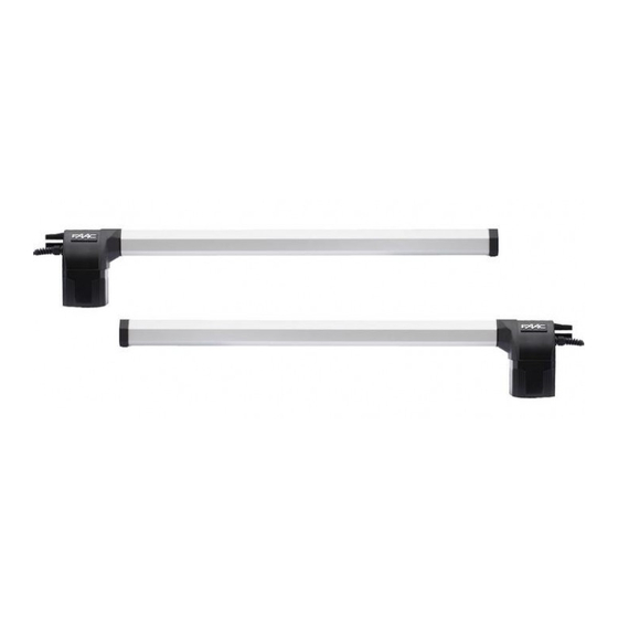
Cover Rear bracket Motor Power cable Cable cover Figure 1. Parts of the 412 Compact Operator (SX model is shown) Figure 2. Mount the proper model (SX or DX) on the gate leaf whether the gate swings inward or outward. -
Page 6: The 412 Low Voltage Operator
The 412 Low Voltage Operator General Characteristics The force of the 412 Operator is controlled by a DIP switch located on the 424 MPS control panel. FAAC recommends that the gate leaf stop if it encounters a The FAAC 412 Compact Operator is an automatic gate force of more than 33 lb (15 kg). -
Page 7: General Operating Logic
412 Operator. Prepare the Gate Before you install the 412 Operator, you need to prepare the gate itself for the operator. Be sure to do the following three things: Figure 4. -
Page 8: Install The Operator
35 1/8 in. (89.2 cm) 4 in. (10 cm) 3 1/8 in. (8 cm) 3 1/8 in. (8 cm) 3 1/8 in. (8 cm) Absolute minimum of 1 3/4 in. (4.5 cm) Figure 5. Important mounting dimensions for inward-swinging 412 operators, top view... -
Page 9: Attach The Operator To The Rear Mounting Bracket
4 in. (10 cm) 3 1/8 in. (8 cm) Absolute minimum of 3 1/8 in. (8 cm) Figure 6. Important mounting dimensions for outward-swinging 412 operators, top view Attach the Operator to the Rear Attach the Operator to the Front... -
Page 10: Attach The Front Mounting Bracket To The Gate Leaf
Attach the Front Mounting Bracket to the Gate Leaf Disengage the operator’s worm screw drive from its motor with the Manual Release. Insert the key in the top of the motor assembly, and turn the key a half turn in the direction of the gate’s closing. You should be able to lengthen or shorten the cylinder by pulling or pushing it. -
Page 11: Install The 424 Mps Control Panel
Locate switches at least 10 ft from the gate Gate Elements Wire Gauges for Given Voltage × 412 Operators: Note: Each requires a junction box 18 AWG for accessories × Photocells 14 AWG for the operators ×... -
Page 12: Connect The Batteries
Figure 12. The 424 MPS control box Connect the Batteries Terminals 5 and 6 on the M1 terminal block provide a 24 volt dc output for accessories. Terminal 5 is positive WARNING! Turn the main power off before you and terminal 6 is negative. Maximum output is 500mA. make any electrical connections or set any switches inside the control panel box. -
Page 13: Connect Other Devices
Figure 13. Wiring detail of the 412 operator to the 424 MPS Connecting the Operator(s) releasing due to back pressure, it may be necessary to utilize the reversing stroke feature by turning DIP switch 5 on. If your gate system has one operator, connect the brown... - Page 14 Figure 14. The 424 MPS layout and wiring diagram...
- Page 15 Figure 15. Common accessories wired to the 424 MPS...
-
Page 16: Set Operating Controls
The FTO (DL2) and STOP (DL3) LEDs indicate whether the input circuits If you are using the FAAC plug-in receiver, connect it for reversing and stop are open or closed. If the light is to the five prong plug labeled “M5” on the 424 MPS on, the circuit is closed. - Page 17 F2 = 10Amp, 250V 4. Give the control panel an activation signal with Logic F3 = 3.15Amp, 250V any normally open device connected to terminals 16 and 19 or with the plug in FAAC radios. When the signal is given, the gate(s)
-
Page 18: Maintenance
The 412 Operator The Control Panel The control panel requires no maintenance, but every The FAAC 412 Operator requires no maintenance. six months you should verify that the torque adjustment Periodically inspect the operator, however, to confirm setting is appropriate. FAAC recommends that the the suitability of the hardware. - Page 19 End cap, 412 protective cover DX 727216 Protective cover, 412 722298 Protective cover support, 412 716056 Motor housing, bottom section, 412 Motor Rotor 710919 Strain relief, 412 390009 Skin pack, 412 (1 pack = 2 operators) Figure 16. 412 Exploded view and parts list...
- Page 20 Neither FAAC S.p.A. or FAAC International, Inc., assumes nor authorizes any person to assume for them any other liability in connection with the sale or use of the products of FAAC S.p.A. or FAAC International, Inc.
Need help?
Do you have a question about the 412 and is the answer not in the manual?
Questions and answers