Table of Contents
Advertisement
Quick Links
AN2018-35 EVAL-M1-IM818-A User Manual
EVAL-M1-IM818-A User Manual
iMOTION™ Modular Application Design Kit
About this document
Scope and purpose
This application note provides an overview of the evaluation board EVAL-M1-IM818-A including its main
features, key data, pin assignments and mechanical dimensions.
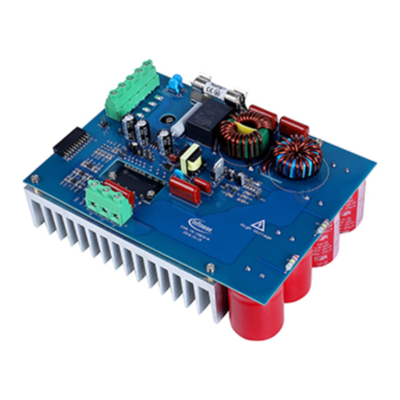
EVAL-M1-IM818-A is a complete evaluation board including a 3-phase CIPOS™ Maxi Intelligent Power Module
(IPM) for motor drive application. In combination with control-boards equipped with the M1 20pin interface
connector, like EVAL-M1-101T or EVAL-M1-099M, it features and demonstrates Infineon's CIPOS™ Maxi IPM
technology for motor drive.
The evaluation board EVAL-M1-IM818-A was developed to support customers during their first steps
designing applications with CIPOS™ Maxi IPM.
CIPOS™ Maxi IPM in this board is IM818-MCC which has three phase inverter with 1200V TRENCHSTOP™
IGBTs and Emitter Controlled diodes are combined with an optimized 6-channel SOI gate driver. It is
Optimized to industrial applications like Ventilation and Air Conditioning.
Intended audience
This application note is intended for all technical specialists working with the EVAL-M1-IM818-A board.
Table of Contents
About this document ....................................................................................................................... 1
Table of Contents ........................................................................................................................... 1
1
Safety precautions ......................................................................................................... 3
2
Introduction .................................................................................................................. 5
3
Main features ................................................................................................................ 6
3.1
EVAL-M1-IM818-A board specifications .................................................................................................. 7
3.2
Pin assignments ...................................................................................................................................... 9
4
Getting Started with EVAL-M1-IM818-A ........................................................................... 11
4.1
Setting up the system............................................................................................................................ 11
4.2
iMOTION™ development tools and software ....................................................................................... 13
4.2.1
MCEWizard setup overview .............................................................................................................. 13
4.2.2
MCEDesigner setup overview .......................................................................................................... 15
5
Hardware description of EVAL-M1-IM818-A ...................................................................... 17
5.1
DC bus Measurement and MCEWizard configuration .......................................................................... 17
5.1.1
Motor External Current feedback configuration and calculation .................................................. 18
5.2
EMI filter and soft power up circuit ....................................................................................................... 21
5.3
Inverter section using CIPOS™ Maxi IPM............................................................................................... 22
5.4
Auxiliary power supply .......................................................................................................................... 23
5.5
Schematic with EVAL-M1-IM818-A evaluation board ........................................................................... 24
5.6
PCB Layout ............................................................................................................................................ 25
6
Bill of Materials of EVAL-M1-IM818-A ............................................................................... 29
User Manual
www.infineon.com
Please read the Important Notice and Warnings at the end of this document
<Revision 1.3>
<2021-04-30>
Advertisement
Table of Contents

Subscribe to Our Youtube Channel
Related Manuals for Infineon iMOTION AN2018-35 EAL-M1-IM818-A


Summary of Contents for Infineon iMOTION AN2018-35 EAL-M1-IM818-A
-
Page 1: Table Of Contents
EVAL-M1-IM818-A is a complete evaluation board including a 3-phase CIPOS™ Maxi Intelligent Power Module (IPM) for motor drive application. In combination with control-boards equipped with the M1 20pin interface connector, like EVAL-M1-101T or EVAL-M1-099M, it features and demonstrates Infineon’s CIPOS™ Maxi IPM technology for motor drive. - Page 2 EVAL-M1-IM818-A User Manual iMOTION™ Modular Application Design Kit Safety precautions Reference ........................32 User Manual <Revision 1.3> <2021-04-30>...
-
Page 3: Safety Precautions
EVAL-M1-IM818-A User Manual iMOTION™ Modular Application Design Kit Safety precautions Safety precautions In addition to the precautions listed throughout this manual, please read and understand the following statements regarding hazards associated with development systems. Table 1 Precautions User Manual <Revision 1.3> <2021-04-30>... - Page 4 EVAL-M1-IM818-A User Manual iMOTION™ Modular Application Design Kit Safety precautions Caution: The ground potential of the EVAL-M1-IM818-A board is biased to a negative DC bus voltage potential. When measuring voltage waveform by oscilloscope, the scope’s ground needs to be isolated. Failure to do so may result in personal injury or death, and equipment damage.
-
Page 5: Introduction
The EVAL-M1-IM818-A evaluation board is available through regular Infineon distribution partners as well as on Infineon's website. The features of this board are described in the design feature chapter of this document, whereas the remaining paragraphs provide information to enable the customers to copy, modify and qualify the design for production according to their own specific requirements. -
Page 6: Main Features
EVAL-M1-IM818-A is an evaluation board for motor drive applications based on a 3-phase IPM. Combined with one of the available MADK control board options, it demonstrates Infineon's IPM technology for motor drives. The kit demonstrates Infineon’s IPM technology for motor drives. -
Page 7: Eval-M1-Im818-A Board Specifications
EVAL-M1-IM818-A User Manual iMOTION™ Modular Application Design Kit Main features EVAL-M1-IM818-A board specifications Table 2 depicts the important specifications of the evaluation board EVAL-M1-IM818-A. Table 2 EVAL-M1-IM818-A board specifications Parameters Values Conditions / comments Input Voltage 380 V ±20% V input Input current Input 380 V... - Page 8 EVAL-M1-IM818-A User Manual iMOTION™ Modular Application Design Kit Main features Figure 2 points out the functional groups on the top side of the EVAL-M1-IM818-A evaluation board. 1. J1 - AC Line connector 2. Relay and Fuse 3. J2 - 20 pin iMOTION™ MADK-M1 interface connector for controller board 4.
-
Page 9: Pin Assignments
EVAL-M1-IM818-A User Manual iMOTION™ Modular Application Design Kit Main features Pin assignments General information about the connectors of the EVAL-M1-IM818-A evaluation board is reported. Table 3 includes the details of the AC line connector J1. Table 3 J1- AC Line connector S. - Page 10 EVAL-M1-IM818-A User Manual iMOTION™ Modular Application Design Kit Main features Table 5 denotes the details of the motor side connector J2. Table 5 J2- Motor side connector S. No. Details Connected to motor phase U Connected to motor phase V Connected to motor phase W User Manual <Revision 1.3>...
-
Page 11: Getting Started With Eval-M1-Im818-A
3. Get the latest “IMC101T-T038 MCE Software Package” available on www.infineon.com/imotion-software web page. (Infineon iMOTION™ control IC IMC101T-T038 is used for control board EVAL-M1-101T). 4. Connect motor phase outputs to the motor. 5. Use MCEWizard to enter the motor and evaluation board hardware parameters and click button “Export to Designer file (.txt)”... - Page 12 EVAL-M1-IM818-A User Manual iMOTION™ Modular Application Design Kit Getting Started with EVAL-M1-IM818-A 6. Connect AC power to power input connector (J1) and power on system. 7. Open MCEDesigner and open MCEDesigner default configuration file (.irc) for IMC101T devices (IMC101T_xx.irc) by clicking “File” menu and select “Open” in the pull down list. 8.
-
Page 13: Imotion™ Development Tools And Software
“Welcome Page” for MCEWizard, where the MADK control board or power board can be selected through the pull-down list. Infineon keeps releasing new MADK controller and power boards. Therefore, it could happen that some of the newest power boards are not pre-configured in the MCEWizard tool and cannot be selected through the pull-down menu. - Page 14 EVAL-M1-IM818-A User Manual iMOTION™ Modular Application Design Kit Getting Started with EVAL-M1-IM818-A There are very limited numbers of parameters which are specific to the control board or power board hardware. Table 6 provides the MCEWizard setup overview for hardware related parameters specific to EVAL-M1- IM818-A power board.
-
Page 15: Mcedesigner Setup Overview
EVAL-M1-IM818-A User Manual iMOTION™ Modular Application Design Kit Getting Started with EVAL-M1-IM818-A Click “Calculate” button and “Export to Designer File (.txt)” button to save the parameter file which will be used by the MCEDesigner in the next steps. 4.2.2 MCEDesigner setup overview After installing MCEDesigner installer, there is a shortcut for MCEDesigner on Windows desktop. - Page 16 Firmware File”. Finally, click on the “Start” button to program the parameter file into the IMC101T-T038 IC. Figure 8 Program Firmware and Parameter in “Program IMC Controller” pop-up window All the latest firmware files for different types of iMOTION motor control ICs are available for download via Infineon iMOTION website (http://www.infineon.com/imotion-software). User Manual <Revision 1.3> <2021-04-30>...
-
Page 17: Hardware Description Of Eval-M1-Im818-A
EVAL-M1-IM818-A User Manual iMOTION™ Modular Application Design Kit Hardware description of EVAL-M1-IM818-A Hardware description of EVAL-M1-IM818-A To meet individual customer requirements and make the EVAL-M1-IM818-A evaluation board a basis for development or modification, all necessary technical data like schematics, layout and components are included in this chapter. -
Page 18: Motor External Current Feedback Configuration And Calculation
EVAL-M1-IM818-A User Manual iMOTION™ Modular Application Design Kit Hardware description of EVAL-M1-IM818-A Figure 10 DC bus sensing configuration in MCEWizard 5.1.1 Motor External Current feedback configuration and calculation The current input value is product of the shunt resistance in milliohms and gain of External current sense amplifier for EVAL-M1-101T as shown in Figure 11. - Page 19 EVAL-M1-IM818-A User Manual iMOTION™ Modular Application Design Kit Hardware description of EVAL-M1-IM818-A Figure 12 depicts IU+ current feedback sensing circuity on EVAL-M1-101T evaluation board. Please note that the default external amplification gain is less than 1 for current sense in this evaluation board. +3.3V Current Shunt iMOTION...
- Page 20 EVAL-M1-IM818-A User Manual iMOTION™ Modular Application Design Kit Hardware description of EVAL-M1-IM818-A Figure 13 Current feedback configuration in MCEWizard for EVAL-M1-101T and EVAL-M1-IM818-A User Manual <Revision 1.3> <2021-04-30>...
-
Page 21: Emi Filter And Soft Power Up Circuit
EVAL-M1-IM818-A User Manual iMOTION™ Modular Application Design Kit Hardware description of EVAL-M1-IM818-A EMI filter and soft power up circuit Figure 14 depicts the schematic from the AC line input connector J1 to the rectified DC bus voltage. This circuitry includes a passive EMI filter consisting of elements C1, C2, L1, L2 and a 40 A/1200 V rectifier block DB, a fuse F1 for inrush current protection, and a relay K1 for soft powering up and reducing conduction losses in steady state. -
Page 22: Inverter Section Using Cipos™ Maxi Ipm
EVAL-M1-IM818-A User Manual iMOTION™ Modular Application Design Kit Hardware description of EVAL-M1-IM818-A Inverter section using CIPOS™ Maxi IPM The inverter section is implemented using the CIPOS™ Maxi IPM as sketched in Figure 15. The module includes an optimized SOI gate driver and three phase inverter with 1200V TRENCHSTOP™ IGBTs and Emitter Controlled diodes. -
Page 23: Auxiliary Power Supply
EVAL-M1-IM818-A User Manual iMOTION™ Modular Application Design Kit Hardware description of EVAL-M1-IM818-A Auxiliary power supply Figure 16 depicts the schematic of the auxiliary power supply available on the EVAL-M1-IM818-A board. The circuit includes IRS2505L that is used to generate 15 V directly from the DC bus. V is connected to the gate drivers inside the CIPOS™... -
Page 24: Schematic With Eval-M1-Im818-A Evaluation Board
EVAL-M1-IM818-A User Manual iMOTION™ Modular Application Design Kit Hardware description of EVAL-M1-IM818-A Schematic with EVAL-M1-IM818-A evaluation board Figure 17 displays schematic with EVAL-M1-IM818-A board T9GS2L14-12 220uH 7.1A DCBUS 27 0.5W +BUS ZTPV-25 32A 1000VDC LED1 10W100ohm IM818-MCC 2200pF 4kV 2200pF 4kV 104 1000V 1mH 4.8A CON7... -
Page 25: Pcb Layout
EVAL-M1-IM818-A User Manual iMOTION™ Modular Application Design Kit Hardware description of EVAL-M1-IM818-A PCB Layout The layout of this board can be used for different voltage or power classes. The PCB has two electrical layers with 35µm copper by default and its size is 197 mm × 140 mm. The PCB board thickness is 1.6mm. Get in contact with our technical support team to get more detailed information and the latest Gerber-files. - Page 26 EVAL-M1-IM818-A User Manual iMOTION™ Modular Application Design Kit Hardware description of EVAL-M1-IM818-A Figure 19 depicts the bottom assembly print of the evaluation board. Figure 19 Bottom assembly print of the EVAL-M1-IM818-A evaluation board User Manual <Revision 1.3> <2021-04-30>...
- Page 27 EVAL-M1-IM818-A User Manual iMOTION™ Modular Application Design Kit Hardware description of EVAL-M1-IM818-A The top layer routing of the PCB is provided in Figure 20. Figure 20 Top layer routing of the EVAL-M1-IM818-A User Manual <Revision 1.3> <2021-04-30>...
- Page 28 EVAL-M1-IM818-A User Manual iMOTION™ Modular Application Design Kit Hardware description of EVAL-M1-IM818-A Figure 21 illustrates the bottom layer routing of the PCB. Figure 21 Bottom layer routing of the EVAL-M1-IM818-A User Manual <Revision 1.3> <2021-04-30>...
-
Page 29: Bill Of Materials Of Eval-M1-Im818-A
EVAL-M1-IM818-A User Manual iMOTION™ Modular Application Design Kit Bill of Materials of EVAL-M1-IM818-A Bill of Materials of EVAL-M1-IM818-A Table 7 provides the complete bill of materials of the evaluation board. Table 7 Bill of materials No. Qty Part description Designator Part number Manufacturer CAP Safety 2200PF 4KV C1, C2... - Page 30 EVAL-M1-IM818-A User Manual iMOTION™ Modular Application Design Kit Bill of Materials of EVAL-M1-IM818-A No. Qty Part description Designator Part number Manufacturer 3-PHASE BRIDGE RECT 1200V 40A GUO40-12NO1 IXYS FUSE CERAMIC 32A 1000VDC ZTPV-32 LKET CONN TERM BLOCK 5POS 9.52MM 691250910003 Wurth Electronics Inc.
- Page 31 TEST POINT PC MAXI .040""D RED IV, IW, U, UH, UL, V, VH, VL, VTH, W, WH, WL, IC REG LINEAR 3.3V 1A SOT223-4 IFX1117MEV33HTMA1 Infineon Technologies DIODE SCHOTTKY 30V 500MA D8, D9, D10 BAS3005A02VH6327X Infineon Technologies SC79-2 TSA1 1200 V, 3-phase Intelligent Power...
- Page 32 EVAL-M1-IM818-A User Manual iMOTION™ Modular Application Design Kit Reference Reference [1] Datasheet of Infineon CIPOS™ Maxi IM818, is available for download on Infineon’s website https://www.infineon.com/cms/en/product/power/intelligent-power-modules-ipm/cipos-maxi/ [2] Application Note AN2016-10 CIPOS Maxi Technical Description, is available for download on Infineon’s website All listed reference materials are available for download on Infineon’s website...
- Page 33 EVAL-M1-IM818-A User Manual iMOTION™ Modular Application Design Kit Table of Contents Revision History Major changes since the last revision Version number Revision Date Revision description 2018-11-15 First release 2019-04-02 Change output power to 1500W and Current to 2.35A. Optimization schematic 2021-03-03 Change current feedback sensing value to 20.83mV/A 2021-04-30...
- Page 34 Trademarks of Infineon Technologies AG AURIX™, C166™, CanPAK™, CIPOS™, CoolGaN™, CoolMOS™, CoolSET™, CoolSiC™, CORECONTROL™, CROSSAVE™, DAVE™, DI-POL™, DrBlade™, EasyPIM™, EconoBRIDGE™, EconoDUAL™, EconoPACK™, EconoPIM™, EiceDRIVER™, eupec™, FCOS™, HITFET™, HybridPACK™, Infineon™, ISOFACE™, IsoPACK™, i-Wafer™, MIPAQ™, ModSTACK™, my-d™, NovalithIC™, OmniTune™, OPTIGA™, OptiMOS™, ORIGA™, POWERCODE™, PRIMARION™, PrimePACK™, PrimeSTACK™, PROFET™, PRO-SIL™, RASIC™, REAL3™, ReverSave™, SatRIC™, SIEGET™, SIPMOS™, SmartLEWIS™, SOLID FLASH™, SPOC™, TEMPFET™,...
Need help?
Do you have a question about the iMOTION AN2018-35 EAL-M1-IM818-A and is the answer not in the manual?
Questions and answers