Table of Contents
Advertisement
Quick Links
Video-inserter
CI-RL5-MIB-STD2
Video-inserter with 1 video input and 1 rear-view camera input
Compatible with VW vehicles
with Composition Media or Discover Media system
Skoda vehicles with Amundsen or Bolero system
Seat vehicles with Media system plus
Product features
Video-inserter for factory-infotainment systems
1 CVBS video-input for after-market device (e.g. USB-Player, DVB-T2 tuner)
1 CVBS rear-view camera video-input
Automatic switching to rear-view camera input on engagement of the reverse gear
Video-in-motion (ONLY for connected video-sources)
Video-inputs NTSC and PAL compatible
Version 09.08.2021
HW (V31)
CI-RL5-MIB-STD2
Advertisement
Table of Contents

Related Manuals for Car-Interface CI-RL5-MIB-STD2


Summary of Contents for Car-Interface CI-RL5-MIB-STD2
- Page 1 Video-inserter CI-RL5-MIB-STD2 Video-inserter with 1 video input and 1 rear-view camera input Compatible with VW vehicles with Composition Media or Discover Media system Skoda vehicles with Amundsen or Bolero system Seat vehicles with Media system plus Product features Video-inserter for factory-infotainment systems ...
-
Page 2: Table Of Contents
To receive a free update, the interface must be sent in at own cost. Labour cost for and other expenses involved with the software-updates will not be refunded. Version 09.08.2021 HW (V31) CI-RL5-MIB-STD2... -
Page 3: Prior To Installation
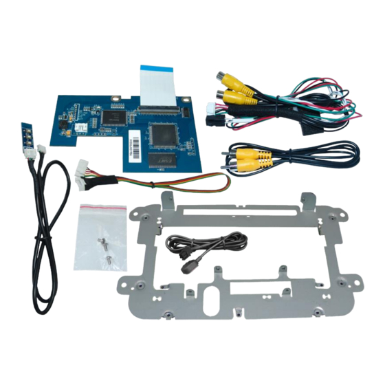
1. Prior to installation Read the manual prior to installation. Technical knowledge is necessary for installation. The place of installation must be free of moisture and away from heat sources. 1.1. Delivery contents Version 09.08.2021 HW (V31) CI-RL5-MIB-STD2... - Page 4 For sound use the possibly existing factory audio-AUX-input or a FM- modulator. Factory rear-view camera Automatically switching-back from inserted video to factory rear-view camera is only possible while the reverse gear is engaged. To delay the switch-back, an additional electronic part is required. Version 09.08.2021 HW (V31) CI-RL5-MIB-STD2...
-
Page 5: Connectors - Video Interface (Daughter Pcb)
If power source is not taken directly from the battery, the connection has to be checked for being start-up proven and permanent. 2.1. Place of installation The daughter PCB shell be connected inside the factory head unit housing and installed by using the delivered exchange metal frame Version 09.08.2021 HW (V31) CI-RL5-MIB-STD2... -
Page 6: Connection Scheme
2.2. Connection Scheme Version 09.08.2021 HW (V31) CI-RL5-MIB-STD2... -
Page 7: Installation - Ribbon Cables Into The Monitor Panel
60pin ribbon cable base and connect it to the 60pin ribbon cable base at the daughter PCB’s bottom side (heed the following warning notes!). Connect the daughter PCB’s pre-assembeled 60pin ribbon cable to the previously become free 60pin ribbon cable base of the mainboard. (heed the following warning notes!). Version 09.08.2021 HW (V31) CI-RL5-MIB-STD2... -
Page 8: Warning Notes, Concerning The Installation Of Ribbon Cables
180° position to the connector. Each deviation from a perfect contact position will curse faulty contact and even danger of short circuit 2) The ribbon cable’s contacting side always has to correspond to the contacting side of the connector, concerning the mounting position. Version 09.08.2021 HW (V31) CI-RL5-MIB-STD2... -
Page 9: Cable Connection - Daughter Pcb
Connect the 6pin interface cable’s single red colored wire to +12V terminal 30 (e.g. glove compartment illumination). Connect the 6pin interface cable’s single green colored wire to +12V reverse signal (see following chapter). Connect the 6pin interface cable’s black wire to vehicle Ground. Version 09.08.2021 HW (V31) CI-RL5-MIB-STD2... -
Page 10: After-Market Rear-View Camera
(87). Connect the reverse light’s power to the relay’s coil terminal (85). Connect permanent power to the relay’s input terminal (30). Connect vehicle’s ground to the relay’s coil terminal (86). Version 09.08.2021 HW (V31) CI-RL5-MIB-STD2... -
Page 11: Connection - Video Inputs
Connect the rear-view camera’s RCA to the 8pin interface cable’s female RCA „Camera IN“. Connect the RCA of the video source to the 8pin interface cable’s female RCA „Video IN1“. Version 09.08.2021 HW (V31) CI-RL5-MIB-STD2... -
Page 12: Connection - Keypad
2.7. Connection – external keypad Connect the keypad’s female 4pin connector to the male 4pin connector of the 6pin interface cable. Version 09.08.2021 HW (V31) CI-RL5-MIB-STD2... -
Page 13: Interface Operation By External Keypad
Contrast Brightness Saturation Position H (horizontal) Position V (vertical) IR-AV1/2 (no function) Guide L/R (no function) UI-CNTRL (no function) Size H/V (picture size horizontal/vertical) Note: To adjust the reverse picture settings, engage the reverse gear. Version 09.08.2021 HW (V31) CI-RL5-MIB-STD2... -
Page 14: Specifications
Video input 0.7V - 1V Video input formats NTSC / PAL RGB-video amplitude 0.7V with 75 Ohm impedance Temperature range -40°C to +85°C Dimensions PCB1 123x 11 x 76 mm (W x H x D) Version 09.08.2021 HW (V31) CI-RL5-MIB-STD2... - Page 15 Apply +12V from the reverse light. Use a relay or camera input when reverse cable doesn’t receive the electronics to "clean" reverse gear lamp power. gear is engaged. +12V reverse signal 10R-03 5384 Made in China Version 09.08.2021 HW (V31) CI-RL5-MIB-STD2...
Need help?
Do you have a question about the CI-RL5-MIB-STD2 and is the answer not in the manual?
Questions and answers