Table of Contents
Advertisement
Quick Links
READ AND SAVE THESE INSTRUCTIONS
50" Ceiling Fan Owner's Manual
CF712AB02
Antique Brass
CF712AW02
Summer White
CF712BS02
Brushed Steel
Questions, problems, missing parts: Before returning to the store call
Emerson Electric Customer Service - 8 a.m. - 6 p.m., Eastern, Monday-Friday
Part No. F40BP73000007
Revision: 150226
PRO SERIES™
Model Numbers
Net Weight:
1-800-654-3545
www.emersonfans.com
CF712ORB02
Oil Rubbed Bronze
with Amber Scavo Glass
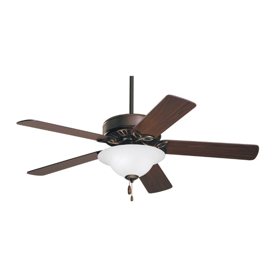
CF712WORB02
Oil Rubbed Bronze with Opal
Matte Glass
CF712WW02
Appliance White
19.0
Lbs.
• Español - página 29
• Français - page 57
Form No. BP7300-7
U.L. Model No.: 52-ANT
Advertisement
Table of Contents

Related Manuals for Emerson PRO CF712WORB


Summary of Contents for Emerson PRO CF712WORB
- Page 1 19.0 Net Weight: Lbs. Questions, problems, missing parts: Before returning to the store call Emerson Electric Customer Service - 8 a.m. - 6 p.m., Eastern, Monday-Friday • Español - página 29 1-800-654-3545 • Français - page 57 Part No. F40BP73000007 Form No.
-
Page 2: Table Of Contents
3. Do not put anything into the fan blades while they are WARNING: To avoid fire, shock or injury, do not use an turning. Emerson or any other brand of control not specifically approved for this fan. 4. Do not operate reversing switch until fan blades have come to a complete stop. -
Page 3: Unpacking Instructions
Emerson Electric Co. Substitution of parts or 60-Watt (max.) Candelabra Base Bulbs accessories not designated for use with this product by Emerson Electric Co. could result in personal injury Blade Flanges or property damage. Fan Blades Open carton containing fan. -
Page 4: Electrical Requirements
Turning off wall switch is not sufficient. To avoid possible electrical shock, be sure electricity is turned Please call Emerson technical support off at the main fuse box before wiring. All wiring must 1-800-654-3545 if you have any questions about be in accordance with National and Local codes and installation and operation of this ceiling fan. -
Page 5: Removal Of The Hanger Bracket
IMPORTANT Your ceiling fan is designed to be installed either in the standard manner, or in the close-to-the-ceiling manner. Using the standard method, the hanger ball/downrod assembly will suspend the fan several inches below the ceiling cover. Using the close-to-the-ceiling method, the ceiling cover installs directly on the fan motor housing, thus mounting the fan 3-1/2 inches closer to the ceiling than the standard method. -
Page 6: Installing The Hanger Ball/Downrod Assembly (Standard)
4. Installing the Hanger Ball/Downrod Assembly (For Standard Mounting) THREE 42" Pass the 42" motor leads through the opening in the MOTOR LEADS ceiling cover. Be sure the cover is oriented correctly (Figure 2). CEILING COVER Figure 2 THREE 42" Separate, untwist and unkink the three motor leads. - Page 7 4. Installing the Hanger Ball/Downrod Assembly (For Standard Mounting) (Continued) HAIRPIN DOWNROD CLIP Loosen the two setscrews in the motor coupling. CLEVIS Place the hanger ball/downrod assembly into the motor coupling, aligning the clevis pin holes in the downrod CLEVIS with the holes in the motor coupling (Figure 4).
-
Page 8: Installing The Ceiling Cover On The Fan Motor Housing (Close-To-Ceiling)
5. Installing the Ceiling Cover on the Fan Motor Housing (For Close-to-the-Ceiling Mounting) Remove three motor housing screws (every other screw as illustrated) from the top of the motor housing (Figure 6). Retain the three motor housing screws for future use. REMOVE SCREWS (3) MOTOR HOUSING... - Page 9 5. Installing the Ceiling Cover on the Fan Motor Housing (For Close-to-the-Ceiling Mounting) (Continued) Gently pry the decorative cap from the ceiling cover DECORATIVE CAP (Figure 8). CEILING COVER Figure 8 SCREWS (3) (Previously Removed) Align the holes in the ceiling cover with the holes in the motor housing and secure using the three screws CEILING COVER previously removed in Step 5.1 (Figure 9).
-
Page 10: How To Hang Your Ceiling Fan
6. How to Hang Your Ceiling Fan WARNING CEILING The fan must be hung with at least 7' of clearance from floor to blades (Figure 9). WARNING The outlet box and joist must be securely mounted and capable of supporting at least 50 lbs. Use only a U.L. outlet box listed as “Acceptable for Fan Support of 22.7 kg. -
Page 11: Hanging The Ceiling Fan (Standard)
6. How to Hang Your Ceiling Fan (Continued) NOTE: The hanger bracket must be mounted flush with the ceiling in order for the ceiling cover to install properly. If necessary, use leveling washers (not supplied) between the outlet box and the hanger bracket. -
Page 12: Hanging The Ceiling Fan (Close-To-Ceiling)
8. Hanging the Ceiling Fan (Close-to-the-Ceiling Method with Ceiling Cover Installed on the Motor Housing) Carefully lift the fan assembly up to the hanger bracket. Pass the hook on the hanger bracket (Figure 13) through one of the screw holes (not the slots) in the ceiling cover (Figure 13). -
Page 13: How To Wire Your Ceiling Fan
9. How to Wire Your Ceiling Fan The following instructions show that the Hanger Ball/Downrod Assembly and the Close-To-The-Ceiling Assembly wiring instructions are the same. If you feel that you do not have enough electrical Hanger Ball/Downrod Assembly Shown wiring knowledge or experience, have your fan installed by a licensed electrician. - Page 14 9. How to Wire Your Ceiling Fan (Continued) Hanger Ball/Downrod Assembly Shown Securely connect the fan motor black wire and blue wire to the supply black (hot) wire using wire connector LISTED WIRE CONNECTOR supplied (Figure 16). SUPPLY BLACK (HOT) BLUE WIRE FAN MOTOR...
-
Page 15: Installing The Ceiling Cover
10. Installing the Ceiling Cover 10.1 Hanger Ball/Downrod Assembly Shown Remove the left screw and lockwasher from each side of the hanger bracket (Figure 18) and loosen the other NOTE: When installing the ceiling fan using the two screws. close-to-the-ceiling method, carefully lift the fan assembly from the hook on the hanger bracket and REMOVE LEFT SCREW AND... -
Page 16: Installing The Fan Blades
11. Installing the Fan Blades 11.1 WARNING M5 x 6 WASHER HEAD BLADE SCREW (3) To reduce the risk of personal injury, do not bend the FAN BLADE blade flanges when installing the flanges, balancing the blades, or cleaning the fan. Do not insert foreign objects between rotating fan blades. -
Page 17: Installing The Light Fitter
12. Installing the Light Fitter and Glass 12.1 SWITCH HOUSING Remove and retain the three screws securing the SCREW (3) switch housing cover to the switch housing. (Figure 21) SWITCH HOUSING COVER Figure 21 12.2 Remove and retain the two wire connectors in the SWITCH HOUSING switch housing (Figure 22). - Page 18 12. Installing the Light Fitter and Glass (Continued) 12.4 LIGHT FITTER Remove and retain the lockwasher and nut from the LIGHT FITTER NUT LOCKWASHER light fitter (Figure 24). Insert the black and white wires from the light fitter through the center hole in the switch housing cover (Figure 24).
- Page 19 12. Installing the Light Fitter and Glass (Continued) 12.7 Connect the blue wire from the ceiling fan to the black CEILING FAN wire of the light fitter. Use wire connector (previously BLUE WIRE removed) to make the connection (Figure 27). WIRE CONNECTOR LIGHT FITTER...
- Page 20 12. Installing the Light Fitter and Glass (Continued) 12.10 Remove the finial nut and outer bowl cap from the light kit assembly (Figure 30). Pass the fan switch pull chain through the bushing in FAN SWITCH the bowl cap (Figure 30). PULL CHAIN LIGHT KIT ASSEMBLY...
-
Page 21: Using Your Ceiling Fan
13. Using Your Ceiling Fan 13.1 REVERSING SWITCH Restore electrical power to the outlet box by turning the electricity on at the main fuse box. Check the operation of the fan by gently pulling on the light kit assembly pull chain. Your fan is shipped from the factory with the reversing switch positioned to circulate air downward. -
Page 22: Maintenance
The use of any other control not specifically approved accessories not designated for use with this product for this fan could result in fire, shock and personal by Emerson Electric Co. could result in personal injury injury. or property damage. -
Page 23: Trouble Shooting
17. Trouble Shooting WARNING: FOR YOUR OWN SAFETY TURN OFF POWER AT FUSE BOX OR CIRCUIT BREAKER BEFORE TROUBLE SHOOTING YOUR FAN. TROUBLE PROBABLE CAUSE SUGGESTED REMEDY 1. Fan will not start. 1. Fuse or circuit breaker blown. 1. Check main and branch circuit fuses or circuit WARNING: Make sure main power is breakers. -
Page 24: Repair Parts
18. Repair Parts U.L. Model No.: 52-ANT... - Page 25 18. Repair Parts Listing Model Numbers Description CF712AB02 CF712WW02 CF712AW02 CF712BS02 CF712ORB02 CF712WORB02 Hanger Pack Assembly, 762231 762231-1 762231-2 762231-4 762231-8 762231-8 Consisting of: Hanger Bracket — — — — — — Hanger Ball/ Downrod Assembly — — — — —...
- Page 26 Notes U.L. Model No.: 52-ANT...
-
Page 27: Ceiling Fan Limited Warranty
What We Will Do To Correct Problems: If during the one (1) year warranty period the motor or any component or accessory of your Emerson Ceiling Fan is defective in materials or workmanship, or if during the expected lifetime of the Emerson Ceiling Fan (when used in accordance with the User Manual or other instructions) the motor is defective in materials or workmanship, you must contact Emerson during the applicable warranty period. - Page 28 Air Comfort Products DIVISION OF EmErSON ElEctrIc cO. 8100 W. Florissant • St. louis, mO 63136 Questions, problems, missing parts: Before returning to the store call Emerson Electric Customer Service 8 a.m. - 6 p.m., Eastern, Monday-Friday 1-800-654-3545 www.emersonfans.com Retain this manual for future use.
Need help?
Do you have a question about the PRO CF712WORB and is the answer not in the manual?
Questions and answers