Table of Contents
Advertisement
Quick Links
Advertisement
Table of Contents

Related Manuals for Emerson PRO CF712AB01


Summary of Contents for Emerson PRO CF712AB01
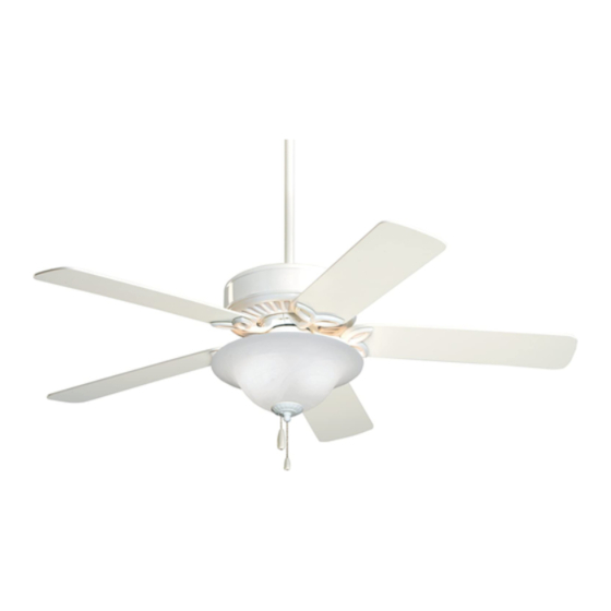
- Page 1 READ AND SAVE THESE INSTRUCTIONS CF712AB01 CF712AW01 CF712BS01 CF712OB01 PRO Series Ceiling Fan Owner's Manual Part No. F40BP73000002 Model No. CF712ORB01 CF712TZ01 CF712WB01 CF712WW01 19.0 Net Weight: Lbs. Form No. BP7300-2 U.L. Model No.: 52-ANT...
-
Page 2: Safety Instructions
4. The downrod furnished with the fan provides the minimum recommended floor to fan blade clearance for an 8-foot ceiling. 5. The fan must be mounted with the fan blades at least 7 feet from the floor to prevent accidental contact with the fan blades. -
Page 3: Unpacking Instructions
This will insure that all steps have been completed and will be helpful in finding your place should you be interrupted. WARNING Do not install or use fan if any part is damaged or missing. Call Toll-Free: 1-800-654-3545... -
Page 4: Removal Of The Hanger Bracket
(Figure 2). NOTE: The setscrews must be properly installed as described above, or fan wobble could result. 5.The fan comes with blue, black and white leads that are 42” long. Measure up approximately 6 to 9-inches above top of hanger ball/downrod assembly. -
Page 5: Installing The Ceiling Cover On The Fan Motor Housing
1/2-inch from ends of leads. Installing The Hanger Bracket WARNING The fan must be hung with at least 7' of clearance from floor to blades (Figure 5). FLOOR Figure 5 The outlet box and joist must be securely mounted and capable of supporting at least 50 lbs. -
Page 6: Electrical Requirements
Consult a qualified electrician if in doubt. If your fan is to replace an existing ceiling light fixture, turn electricity off at the main fuse box at this time and remove the existing light fixture. -
Page 7: Installing The Fan Blades
2. Securely connect the fan motor white wire to the supply white (neutral) wire using wire connector supplied (Figure 10). Securely connect the fan motor black wire and blue wire to the supply black (hot) wire using wire connector supplied (Figure 10). -
Page 8: Installing The Light Fitter
Reinstall the lockwasher and nut and tighten securely (Figure 15). 3. Connect the white wire from the ceiling fan to the white wire of the light fitter (Figure 15). Connect the blue wire from the ceiling fan to the black wire of the light fitter. -
Page 9: Maintenance
This product is designed to use only those parts supplied with this product and/or any accessories designated specifically for use with this product by Emerson Electric Company. Substitution of parts or accessories not designated for use with this product by Emerson Electric Company could result in personal injury or property damage. -
Page 10: Troubleshooting
3. Check to be sure screws which attach the fan blade flanges to the motor are tight. 4. Check to be sure the fan blade flanges seat firmly and uniformly to the surface of the motor. 5. Tighten the hanger bracket screws to the outlet box, and/or secure outlet box. -
Page 11: Limited Warranty
You will be responsible for all insurance, freight or other transportation charges to our factory or authorized service center. Your Emerson Air Comfort Ceiling Fan should be properly packed to avoid damage in transit since we will not be responsible for any such damage. -
Page 12: How To Order Repair Parts
762892-6 762892-7 762891-5 762891-6 762891-7 BP7300-2 BP7300-2 BP7300-2 parts have been removed. • PART DESCRIPTION • MODEL NUMBER Air Comfort Products DIVISION OF EMERSON ELECTRIC CO. Printed in China 08/06 — — 762229 — — — — — — —...
Need help?
Do you have a question about the PRO CF712AB01 and is the answer not in the manual?
Questions and answers