Table of Contents
Advertisement
Available languages
Available languages
Quick Links
READ AND SAVE THESE INSTRUCTIONS
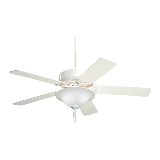
50" Ceiling Fan Owner's Manual
CF712AB03
Antique Brass
CF712BS03
Brushed Steel
Questions, problems, missing parts: Before returning to the store call
Emerson Electric Customer Service - 8 a.m. - 6 p.m., Eastern, Monday-Friday
Part No. F40BP73000008
Revision: 190329
PRO SERIES LED
Model Numbers
Net Weight:
1-800-654-3545
www.emersonfans.com
CF712WORB03
Oil Rubbed Bronze
CF712WW03
Appliance White
19.0
Lbs.
• Español - página 29
Form No. BP7300-8
U.L. Model No.: 52-ANT
Advertisement
Table of Contents

Related Manuals for Emerson PRO Series


Summary of Contents for Emerson PRO Series
- Page 1 Appliance White 19.0 Net Weight: Lbs. Questions, problems, missing parts: Before returning to the store call Emerson Electric Customer Service - 8 a.m. - 6 p.m., Eastern, Monday-Friday 1-800-654-3545 • Español - página 29 www.emersonfans.com Part No. F40BP73000008 Form No. BP7300-8 Revision: 190329 U.L.
-
Page 2: Table Of Contents
Emerson Electric Co. Substitution of parts or accessories not designated for use with this product 2. All wiring must be in accordance with the National by Emerson could result in personal injury or property Electrical Code “ANSI/NFPA 70-2017” and Local damage. -
Page 3: Unpacking Instructions
Emerson Electric Co. Substitution of parts or Flange Set accessories not designated for use with this product by Emerson Electric Co. could result in personal injury Blade Set or property damage. Open carton containing fan. Remove top half of styrofoam unit. -
Page 4: Electrical Requirements
The minimum wire would be a 3-conductor (2-wire with ground) of following size: SW46 Wall Control and SW90 Wall Control (both sold separately) may be used with this 50” PRO Series LED Installed Wire Length Wire Size A.W.G. -
Page 5: Removal Of The Hanger Bracket
IMPORTANT Your ceiling fan is designed to be installed either in the standard manner, or in the close-to-the-ceiling manner. Using the standard method, the hanger ball/downrod assembly will suspend the fan several inches below the ceiling cover. Using the close-to-the-ceiling method, the ceiling cover installs directly on the fan motor housing, thus mounting the fan 3-1/2 inches closer to the ceiling than the standard method. -
Page 6: Installing The Hanger Ball/Downrod Assembly (Standard)
4. Installing the Hanger Ball/Downrod Assembly (For Standard Mounting) Pass the 80" Motor Wires through the opening in the THREE 80" MOTOR Ceiling Cover. WIRES Be sure the Cover is oriented correctly (Figure 2). CEILING COVER Figure 2 Separate, untwist and unkink the Three Motor Wires. THREE 80"... - Page 7 4. Installing the Hanger Ball/Downrod Assembly (For Standard Mounting) (Continued) Loosen the Two Setscrews in the Motor Coupling. DOWNROD HAIRPIN CLIP Place the Hanger Ball / Downrod Assembly into the Motor CLEVIS Coupling, aligning the Clevis Pin Holes in the Downrod with the Holes in the Motor Coupling (Figure 4).
-
Page 8: Installing The Ceiling Cover On The Fan Motor Housing
5. Installing the Ceiling Cover on the Fan Motor Housing (For Close-to-the-Ceiling Mounting) Remove Three Motor Housing Screws (every other screw as illustrated) from the top of the Motor Housing (Figure 6). Retain the Three Motor Housing Screws for future use. REMOVE SCREWS (3) MOTOR HOUSING... - Page 9 5. Installing the Ceiling Cover on the Fan Motor Housing (For Close-to-the-Ceiling Mounting) (Continued) Gently pry the Decorative Cap from the Ceiling Cover (Figure 8). DECORATIVE CAP CEILING COVER Figure 8 Align the Holes in the Ceiling Cover with the Holes in SCREWS (3) the Motor Housing and secure using the Three Screws (Previously Removed)
-
Page 10: How To Hang Your Ceiling Fan
6. How to Hang Your Ceiling Fan WARNING CEILING The fan must be hung with at least 7' of clearance from floor to blades (Figure 11). WARNING The outlet box and joist must be securely mounted and capable of supporting at least 50 lbs. Use only a U.L. outlet box listed as “Acceptable for Fan Support of 22.7 kg. -
Page 11: Hanging The Ceiling Fan (Standard)
6. How to Hang Your Ceiling Fan (Continued) NOTE: The hanger bracket must be mounted flush with the ceiling in order for the ceiling cover to install properly. If necessary, use leveling washers (not supplied) between the outlet box and the hanger bracket. -
Page 12: Hanging The Ceiling Fan
8. Hanging the Ceiling Fan (Close-to-the-Ceiling Method with Ceiling Cover Installed on the Motor Housing) Carefully lift the Fan Assembly up to the Hanger Bracket. Pass the Hook on the Hanger Bracket (Figure 15) through One of the Screw Holes (NOT the slots) in the Ceiling Cover (Figure 15). -
Page 13: How To Wire Your Ceiling Fan
9. How to Wire Your Ceiling Fan The following instructions show that the Hanger Ball/Downrod Assembly and the Close-To-The-Ceiling Assembly wiring instructions are the same. If you feel that you do not have enough electrical HANGER BALL/DOWNROD ASSEMBLY SHOWN wiring knowledge or experience, have your fan installed by a licensed electrician. - Page 14 9. How to Wire Your Ceiling Fan (Continued) Securely connect the Fan Motor Black Wire and Blue HANGER BALL/DOWNROD ASSEMBLY SHOWN Wire to the Supply Black (Hot) Wire using Wire Connector Supplied (Figure 18). LISTED WIRE CONNECTOR SUPPLY BLACK (HOT) BLUE FAN WIRE FAN MOTOR...
-
Page 15: (Close-To-Ceiling)
10. Installing the Ceiling Cover 10.1 HANGER BALL/DOWNROD ASSEMBLY SHOWN Remove the Left Screw and Lockwasher from each side of the Hanger Bracket (Figure 20) and loosen the other Two Screws. NOTE: When installing the ceiling fan using the close-to-the-ceiling method, carefully lift the fan REMOVE LEFT assembly from the hook on the hanger bracket and SCREW AND... -
Page 16: Installing The Fan Blades
11. Installing the Fan Blades 11.1 WARNING M5 x 6 WASHER HEAD BLADE SCREW (3) To reduce the risk of personal injury, do not bend the FAN BLADE blade flanges when installing the flanges, balancing the blades, or cleaning the fan. Do not insert foreign objects between rotating fan blades. -
Page 17: Installing The Light Fitter
12. Installing the Light Fitter and Glass 12.1 Remove and Retain the Three Screws securing the SWITCH HOUSING Switch Housing Cover to the Switch Housing SCREW (3) (Figure 24). SWITCH HOUSING COVER Figure 24 12.2 Remove and Retain the Two Wire Connectors in the Switch Housing (Figure 25). - Page 18 12. Installing the Light Fitter and Glass (Continued) 12.4 Remove and Retain the Lockwasher and Nut from the Light Fitter (Figure 27). LIGHT FITTER LIGHT FITTER NUT LOCKWASHER Insert the Black and White Wires from the Light Fitter through the Center Hole in the Switch Housing Cover (Figure 27).
- Page 19 12. Installing the Light Fitter and Glass (Continued) 12.6 Connect the White Wire from the Ceiling Fan to the White Wire of the Light Fitter using the previously removed Wire Connector (Figure 29). CEILING FAN WHITE WIRE WIRE CONNECTOR LIGHT FITTER WHITE WIRE LIGHT FITTER ASSEMBLY...
- Page 20 12. Installing the Light Fitter and Glass (Continued) 12.8 Carefully tuck all Wires and Splices into the Switch Housing. SCREW (3) Attach the Switch Housing Cover with Light Fitter (light fitter assembly) to the Switch Housing using the Three previously removed Screws (Figure 31). LIGHT FITTER ASSEMBLY WARNING...
- Page 21 12. Installing the Light Fitter and Glass (Continued) 12.10 Remove the Finial Nut and Outer Bowl Cap from the Light Fitter Assembly (Figure 33). Pass the Fan Switch Pull Chain through the Bushing in FAN SWITCH PULL CHAIN the Bowl Cap (Figure 33). LIGHT FITTER ASSEMBLY OUTER BOWL CAP...
-
Page 22: Using Your Ceiling Fan
13. Using Your Ceiling Fan 13.1 Restore Electrical Power to the Outlet Box by turning REVERSING SWITCH the Electricity on at the Main Fuse Box. During Summer Months, run the Fan Counter- Clockwise, as you look up at it, to direct airflow downward. -
Page 23: Maintenance
Abrasive cleaning agents are not required and should be avoided to prevent damage to finish. See your local Emerson dealer, www.emersonfans.com or the Emerson Ceiling Fan Catalog for these Accessories: • Ceiling Fan/Light Controls • Downrod Extension Kits emersonfans.com... -
Page 24: Repair Parts
17. Repair Parts Parts Bag: U.L. Model No.: 52-ANT... - Page 25 17. Repair Parts Listing Part Numbers Model Number Model Number Model Number Model Number Description CF712AB03 CF712WW03 CF712BS03 CF712WORB03 Hanger Pack Assembly, Consisting of: Hanger Bracket — — — — 762231 762231-1 762231-4 762231-8 Hanger Ball/Downrod Assembly — — — —...
-
Page 26: Troubleshooting
18. Troubleshooting WARNING FOR YOUR OWN SAFETY TURN OFF POWER AT FUSE BOX OR CIRCUIT BREAKER BEFORE TROUBLESHOOTING YOUR FAN. TROUBLE PROBABLE CAUSE SUGGESTED REMEDY 1. Fuse or circuit breaker blown. 1. Check main and branch circuit fuses or circuit 1. -
Page 27: Ceiling Fan Limited Warranty
What We Will Do To Correct Problems: If the defect is covered by this limited warranty, Emerson will repair or replace the applicable Emerson Ceiling Fan Product at no charge to You. If repair of the Emerson Ceiling Fan Product is not practical or possible within a reasonable time and no replacement Emerson Ceiling Fan Product can be provided, Emerson will refund You the actual purchase price of Your Emerson Ceiling Fan Product. - Page 28 The date code of this fan may be found on the box, stamped in ink on a white label. You should record this data above and keep it in a safe place for future use. Air Comfort Products DIVISION OF EmErSON ElEctrIc cO. 8100 W. Florissant • St. louis, mO 63136 Questions, problems, missing parts: Before returning to the store call Emerson Electric Customer Service 8 a.m.
-
Page 29: Spanish
Peso neto: Preguntas, problemas, piezas faltantes: Antes de devolver el producto a la tienda, llame a Servicio al Cliente de Emerson Electric - 8 a.m. a 6 p.m., Hora del Este, lunes a viernes 1-800-654-3545 • English - page 1 No. - Page 30 1. Para evitar posibles descargas eléctricas, asegúrese de que la específicamente por Emerson Electric Co. para utilizarse con este electricidad esté desconectada en la caja de fusibles antes de producto. La sustitución con piezas o accesorios no diseñados por realizar el cableado, y no utilice el ventilador sin paletas.
- Page 31 Emerson Electric Co. para utilizarse con Conjunto de pestañas este producto. La sustitución con piezas o accesorios no diseñados por Emerson Electric Co. para utilizarse con este Conjunto de paletas producto podría causar lesiones corporales o daños materiales.
- Page 32 Si tiene dudas, consulte a un electricista calificado. con licencia. ADVERTENCIA Sírvase llamar a asistencia técnica de Emerson al 1-800-654-3545 si tiene alguna pregunta sobre la instalación y utilización de este ventilador de techo. No basta con poner el interruptor de pared en la posición de apagado.
- Page 33 IMPORTANTE Su ventilador de techo está diseñado para instalarse de la manera estándar o de la manera cerca del techo. Al utilizar el método estándar, el ensamblaje de esfera de suspensión/varilla descendente suspenderá el ventilador varias pulgadas por debajo de la cubierta del techo. Al utilizar el método cerca del techo, la cubierta del techo se instala directamente sobre la carcasa del motor del ventilador, con lo cual el ventilador se monta 3-1/2 pulgadas más cerca del techo que en el método estándar.
- Page 34 4. Instalación del ensamblaje de esfera de suspensión/varilla descendente (para realizar el montaje estándar) TRES CABLES Pase los cables de conexión del motor de 80 pulgadas a través de DE CONEXIÓN DEL THREE 42" MOTOR MOTOR DE 80 PULG. la abertura ubicada en la cubierta del techo. LEADS Asegúrese de que la cubierta esté...
- Page 35 4. Instalación del ensamblaje de esfera de suspensión/varilla descendente (para realizar el montaje estándar) (cont.) VARILLA Afloje los dos tornillos de ajuste ubicados en el acoplamiento del CLIP DE DESCENDENTE DOWNROD HORQUILLA HAIRPIN motor. CLIP PASADOR DE HORQUILLA CLEVIS Coloque el ensamblaje de esfera de suspensión/varilla descen dente en el interior del acoplamiento, alineando los agujeros para pasador PASADOR DE de horquilla ubicados en la varilla descendente con los agujeros...
- Page 36 5. Instalación de la cubierta del techo sobre la carcasa del motor del ventilador (para realizar el montaje cerca del techo) Retire tres tornillos (uno de cada dos tornillos, tal y como se muestra en la ilustración) de la parte superior de la carcasa del motor (Figura 6).
- Page 37 5. Instalación de la cubierta del techo sobre la carcasa del motor del ventilador (para realizar el montaje cerca del techo) (cont.) Haga palanca suavemente en la tapa decorativa para retirarla de la TAPA DECORATIVA cubierta del techo (Figura 8). DECORATIVE CAP CUBIERTA DEL TECHO...
- Page 38 6. Cómo colgar su ventilador de techo ADVERTENCIA TECHO CEILING El ventilador se debe colgar con por lo menos 7 pies de holgura desde el piso hasta las paletas (Figura 11). ADVERTENCIA La caja de tomacorriente y la viga deben estar montadas de POR LO manera segura y ser capaces de soportar por lo menos 50 lb.
- Page 39 6. Cómo colgar su ventilador de techo (continuación) NOTA: El soporte de suspensión se debe montar al ras con el techo para que la cubierta del techo se instale correctamente. Si es necesario, utilice arandelas niveladoras (no sumi - nistradas) entre la caja de tomacorriente y el soporte de suspensión.
- Page 40 8. Suspensión del ventilador de techo (método cerca del techo con la cubierta del techo instalada sobre la carcasa del motor) Levante cuidadosamente el ensamblaje del ventilador hasta el soporte de suspensión. Pase el gancho ubicado en el soporte de suspensión (Figura 15) a través de uno de los agujeros para tornillo (no lo pase a través de las ranuras) ubicados en la cubierta del techo (Figura 15).
- Page 41 9. Cómo cablear su ventilador de techo Las siguientes instrucciones muestran que las instrucciones de cableado son las mismas para el ensamblaje de esfera de suspensión/varilla descendente y para el ensamblaje cerca del techo. Se muestra el ensamblaje de esfera de suspensión/varilla descendente HANGER BALL/DOWNROD ASSEMBLY SHOWN CABLE DE Si le parece que no tiene suficientes conocimientos o...
- Page 42 9.Cómo colgar su ventilador de techo (continuación) Conecte de manera segura el cable negro del motor y el cable azul del HANGER BALL/DOWNROD ASSEMBLY SHOWN Se muestra el ensamblaje de esfera de suspensión/varilla descendente ventilador al cable negro de suministro (con corriente) utilizando el CONECTOR DE conector de cables suministrado (Figura 18).
- Page 43 10. Instalación de la cubierta del techo 10.1 HANGER BALL/DOWNROD ASSEMBLY SHOWN Retire el tornillo y la arandela de seguridad de la parte izquierda de Ensamblaje de esfera de suspensión/varilla descendente cada lado del soporte de suspensión (Figura 20) y afloje los otros dos tornillos.
- Page 44 11. Instalación de las paletas del ventilador 11.1 TORNILLO CON CABEZA DE ARANDELA PARA PALETA M5 x 6 (3) ADVERTENCIA M5 x 6 WASHER HEAD BLADE SCREW (3) PALETA DEL VENTILADOR FAN BLADE Para reducir el riesgo de lesiones corporales, no doble las pestañas de la paleta cuando instale dichas pestañas, equilibre las paletas o limpie el ventilador.
- Page 45 12. Instalación del accesorio de iluminación acoplable y el vidrio CARCASA DEL INTERRUPTOR 12.1 SWITCH HOUSING Retire y retenga los tres tornillos que sujetan firmemente la cubierta TORNILLO (3) de la carcasa del interruptor a la carcasa del interruptor (Figura 24). SCREW (3) CUBIERTA DE LA CARCASA DEL...
- Page 46 12. Instalación del accesorio de iluminación acoplable y el vidrio ( cont.) 12.4 TUERCA DEL ACCESORIO ARANDELA DE Retire y retenga la arandela de seguridad y la tuerca del accesorio de DE ILUMINACIÓN SEGURIDAD DEL iluminación acoplable (Figura 27). LIGHT FITTER ACOPLABLE LIGHT FITTER NUT ACCESORIO DE...
- Page 47 12. Instalación del accesorio de iluminación acoplable y el vidrio ( cont.) 12.6 Conecte el cable blanco procedente del ventilador de techo al cable blanco del accesorio de iluminación acoplable utilizando el conector de cables que retiró previamente (Figura 29). CABLE BLANCO DEL VENTILADOR CEILING FAN...
- Page 48 12. Instalación del accesorio de iluminación acoplable y el vidrio ( cont.) 12.8 TORNILLO (3) Introduzca completamente todos los cables y empalmes en la carcasa SCREW (3) del interruptor. Sujete la cubierta de la carcasa del interruptor con el accesorio de ENSAMBLAJE DEL iluminación acoplable (ensamblaje del kit de iluminación) a la carcasa ACCESORIO DE...
- Page 49 12. Instalación del accesorio de iluminación acoplable y el vidrio (cont.) 12.10 Retire la tuerca de remate y la tapa exterior del globo del ensamblaje CADENA DE TIRO DEL del accesorio de iluminación acoplable (Figura 33). INTERRUPTOR DEL FAN SWITCH VENTILADOR Pase la cadena de tiro del interruptor a través del casquillo ubicado en PULL CHAIN...
- Page 50 13. Utilización del ventilador de techo INTERRUPTOR 13.1 Restablezca la alimentación eléctrica a la caja de tomacorriente DE INVERSIÓN REVERSING SWITCH conectando la alimentación eléctrica en la caja de fusibles principal. Durante los meses de verano, utilice el ventilador de manera que rote en sentido contrario al de las agujas del reloj, según mira hacia arriba al ventilador, para dirigir hacia abajo la circulación de aire.
- Page 51 15. Accesorios Vea a su distribuidor local de Emerson, visite www.emersonfans. ADVERTENCIA com o consulte el Catálogo de ventiladores de techo Emerson acerca de estos accesorios: Este producto está diseñado para utilizar únicamente las piezas Controles del ventilador de techo y la luz suministradas con este producto y/o los accesorios diseñados...
- Page 52 17. Piezas de repuesto Parts Bag: Bolsa de piezas: No. de modelo U.L.: 52-ANT...
- Page 53 17. Lista de piezas de repuesto Números de pieza No. de Número de modelo Número de modelo Número de modelo Número de modelo clave Descripción CF712AW03 CF712WW03 CF712BS03 CF712WORB03 Ensamblaje del paquete de suspensión, que consiste en: 762231 762231-1 762231-4 762231-8 Soporte de suspensión —...
- Page 54 18. Resolución de problemas ADVERTENCIA PARA SU PROPIA SEGURIDAD, DESCONECTE LA ALIMENTACIÓN ELÉCTRICA EN LA CAJA DE FUSIBLES O EL CORTACIRCUITO ANTES DE RESOLVER PROBLEMAS EN SU VENTILADOR PROBLEMA CAUSA PROBABLE REMEDIO SUGERIDO 1. Fusible o cortacircuito fundido. 1. Compruebe los fusibles o los cortacircuitos de los circuitos principal y derivado.
- Page 55 Ventilador de Techo Emerson sigue estando bajo garantía, sírvase retener Su recibo u otro comprobante de compra y tener esa información al alcance de la mano cuando envíe su Producto de Ventilador de Techo Emerson a Su lugar de compra o cuando llame a Servicio al Cliente de Emerson. Si Usted llama a Servicio al Cliente de Emerson, antes de Su llamada esté preparado para dar todos los números de modelo mostrados en su Producto de Ventilador de Techo Emerson.
- Page 56 DIVISION OF EmErSON ElEctrIc cO. 8100 W. Florissant • St. louis, mO 63136 Preguntas, problemas, piezas faltantes: Antes de devolver el producto a la tienda, llame a Servicio al Cliente de Emerson Electric 8 a.m. a 6 p.m., Hora del Este, lunes a viernes 1-800-654-3545 www.emersonfans.com...
Need help?
Do you have a question about the PRO Series and is the answer not in the manual?
Questions and answers