Advertisement
Quick Links
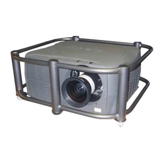
Stacking Frame Installation Instructions
Introduction
Use the following instructions when installing stacking frames onto the models listed in
Table 1. Only use the stacking frame provided by Christie (104-117101-01) to hoist or
stack a maximum of three projectors. The stacking frame can also be connected to the
integral rigging points on any Roadster/Mirage S+ and Roadster HD12k projectors. For
information on the rigging hardware of these models, refer to section 2.2 Installation
Considerations in the Roadster S+/HD & Mirage S+ User's Manual.
Table 1. Projector Models
Projector Model
Christie DS+4K
Christie DS+5K/Kc
Christie DS+8K
DLV1920-DX
DLV1400-DX
Christie DW3K/Kc
Christie DW6K/Kc
Christie HD5K
Christie HD5Kc
Christie HD8K
Christie HD8Kc
Mirage S+2K
Mirage S+4K
Mirage S+8K
Mirage W3
Mirage W6
Mirage W8
Matrix 4000
Matrix W4
013-100342-01 (Rev.1) (08/06)
Model Number
38-DSP104-xx
38-DSP104-xx/38-DSP104-5x
38-DSP106-xx/38-DSP106-5x
104-017101-xx
38-DSP102-xx
38-DHD103-xx/38-DHD103-5x
38-DHD106-xx/38-DHD106-5x
104-006101-xx
104-007101-xx
104-008101-xx
104-018101-xx
38-DSP102-xx/38-DSP102-5x
38-DSP104-xx/38-DSP104-5x
38-DSP106-XX/38-DSP106-5X
104-012101-xx
104-013101-xx
104-014101-xx
38-DSP104--xx
104-016101-xx
1 of 12 pages
Advertisement

Subscribe to Our Youtube Channel
Related Manuals for Christie 104-006101-XX


Summary of Contents for Christie 104-006101-XX
- Page 1 Mirage S+8K Mirage W3 Mirage W6 Mirage W8 Matrix 4000 Matrix W4 013-100342-01 (Rev.1) (08/06) Model Number 38-DSP104-xx 38-DSP104-xx/38-DSP104-5x 38-DSP106-xx/38-DSP106-5x 104-017101-xx 38-DSP102-xx 38-DHD103-xx/38-DHD103-5x 38-DHD106-xx/38-DHD106-5x 104-006101-xx 104-007101-xx 104-008101-xx 104-018101-xx 38-DSP102-xx/38-DSP102-5x 38-DSP104-xx/38-DSP104-5x 38-DSP106-XX/38-DSP106-5X 104-012101-xx 104-013101-xx 104-014101-xx 38-DSP104--xx 104-016101-xx 1 of 12 pages...
- Page 2 Warnings Christie stacking hardware is required to prevent the top projector from sliding off the stack. Failure to incorporate this hardware may cause injury or death. This procedure must only be performed by a qualified service technician. The frame is designed to support a maximum stacking capacity of three projectors.
- Page 3 Wait for the internal cooling fans to stop before unplugging the unit. people are required to complete this procedure. 1. Turn the projector OFF and disconnect the AC power cord after the cooling fans have stopped. Allow the projector to cool for at least 45 minutes.
- Page 4 1. Place the first projector in the stack on a secure table or cart. For upright stack: Place the projector to be positioned on the bottom of the stack on the table or cart. Ensure the adjustable feet are NOT retracted on the bottom projector.
- Page 5 For inverted position: Remove the pins from the mounts on the top projector. 5. With one person positioned on each side of the projector, lift the top projector onto the bottom projector, aligning all three stacking points between the projectors. The legs should fit inside the stacking mounts.
-
Page 6: Hoisting Procedure
Do not mix orientations in a stack (i.e. inverted and upright). Use this procedure to hoist one projector or a stack of projectors. To hoist a stack, first mount two or three projectors according to the stacking procedure included in these instructions. - Page 7 (two opposite sides). Straps must be placed on either side of designated label on the stacking frame handles. 1. If the projector is inverted retract the adjustable feet to prevent the hoisting hardware from becoming snagged. Always use at least two safety cables when hoisting and attach them to the two eyebolts on the stacking frame.
- Page 8 The four top rigging points have a maximum loading capacity of 800 lbs. each. When hoisting from the bottom of the projector use at least four of the eight rigging points (two opposite sets). Use metric hardware only (M12 thread).
- Page 9 Always use at least two safety cables when hoisting. When hoisting a non-inverted projector or stack, add two rigging eyebolts in the front and rear threaded holes on the top of the projector. Ensure the eyebolts are rated adequately for the load. Secure safety cabling to both eyebolts.
-
Page 10: Projector Alignment
3. Minimize each projector’s zoom until the images are focused. 4. Adjust the zoom and lens offset on the top projector to precisely move its test pattern display onto the bottom test pattern. When it is properly aligned all the Red/Green grid lines in the combined image will turn Yellow. - Page 11 Refer to Figure 9. 6. Adjust the zoom on the top projector to align the edges of its image with the other image and then adjust focus. When aligned, all lines from the combined Red/Green grids will be Yellow.
- Page 12 Technical Support CHRISTIE Digital Systems, Inc. 809 Wellington St. North Kitchener, Ontario, Canada N2G 4Y7 Tel. 519-744-8005 (General) Toll Free 1-800-221-8025 (Technical Support) Fax 519-749-2776 (Service) CHRISTIE Digital Systems, Inc. View Point 200 Ashville Way Wokingham, Berkshire RG41 2PL United Kingdom Tel.
Need help?
Do you have a question about the 104-006101-XX and is the answer not in the manual?
Questions and answers