Table of Contents
Advertisement
Quick Links
Advertisement
Table of Contents

Related Manuals for Dahua Digital Villa VTO2 Series


Summary of Contents for Dahua Digital Villa VTO2 Series
- Page 1 Digital Villa VTO (VTO2 series) User’s Manual V1.0.0...
-
Page 2: Table Of Contents
Table of Contents Product Overview ..................1 Intro to Product....................1 Applicable Models ................... 1 Structure ...................... 2 Front Panel ..................... 2 Rear Panel ...................... 3 Networking Scene ..................4 Installation and Debug ................. 5 Device Wiring ....................5 Device Installation ................... 5 4.2.1 Screw .................... - Page 3 5.2.7 IPC ...................... 16 5.2.8 WIFI Info ..................... 17 Info Search ....................17 5.3.1 Call History ..................18 5.3.2 Alarm Record ..................18 5.3.3 Unlock Record ..................18 Status Statistics..................... 19 Basic Function Introduction ................ 20 Monitor ......................20 Call Function ....................20 Unlock ......................
- Page 4 Important Safeguards and Warnings Please read the following safeguards and warnings carefully before using the product in order to avoid damages and losses. Note: Do not expose the device to lampblack, steam or dust. Otherwise it may cause fire or electric shock. Do not install the device at position exposed to sunlight or in high temperature.
-
Page 5: Product Overview
1 Product Overview 1.1 Intro to Product Digital villa VTO has easy operation, simple installation and support: WIFI Mobile phone live preview Call VTH, and perform video talk Door unlock by card One-click MGT center ... -
Page 6: Structure
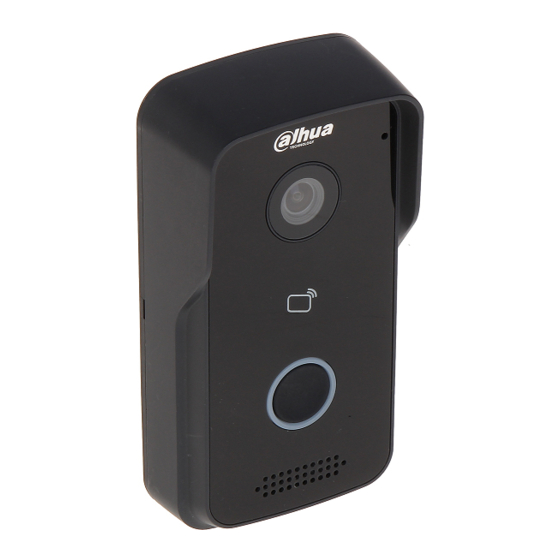
2 Structure 2.1 Front Panel Device front panel is in Figure 2-1. Description of each component is in Chart 2-1. Figure 2-1 Port Name Note Audio input. Camera It monitors corresponding door region. Authorize IC card to unlock (card issuing), Card Area swipe card to unlock. -
Page 7: Rear Panel
2.2 Rear Panel Device rear panel is in Figure 2-2. Description of each component is in Chart 2-2. Figure 2-2 Component Name Note Bracket Position Bracket used to fix device and wall. Vandal-proof When villa VTO is forced to leave wall, it will alarm and Switch send alarm to MGT center. -
Page 8: Networking Scene
3 Networking Scene Villa VTO networking scene is in Figure 3-1. Figure 3-1... -
Page 9: Installation And Debug
4 Installation and Debug 4.1 Device Wiring Device wiring is in Figure 4-1. Figure 4-1 4.2 Device Installation Warning: Avoid installation in poor environment, such as condensation, high temperature, oil stain, dust, corrosion or direct sunlight. Project installation and debugging must be done by professionals. Please do not open the device in case of failure, and please contact after sales service. -
Page 10: Screw
4.2.1 Screw For installation, please use screw according to Chart 4-1. Component Name Illustration Quantity M4×30 cross pan head machine screw Chart 4-1 4.2.2 Installation Step VTH installation is in Figure 4-2. Figure 4-2 Steps: Step 1. According to position of bracket, dig hole on installation surface (such as wall). Step 2. -
Page 11: Debug Device
Note: The recommended distance from device center to ground is 1.4m~1.6m. 4.3 Debug Device 4.3.1 Before Debugging Warning: Debugging personnel shall be familiar with related materials, know device installation, wiring and usage. Debugging personnel check whether circuit has short circuit or open circuit or not. Make sure circuit is normal, plug device to power. -
Page 12: Debug Device
After modification is finished, WEB page will restart and go to new IP address. 4.3.2 Debug Device Make VTH5221D an example here: Step 1. Plug device to power. Step 2. In homepage, long press Settings for 6 seconds. Device pops up Password Verification box. - Page 13 Figure 4-5 2. Enter VTH Local IP, Subnet Mask and Gateway. 3. Press OK. Now device interface shows at the upper right corner which means wired connection is successful. Note: You also can enable DHCP to auto gain VTH IP, subnet mask and gateway and press OK to complete wired connection.
- Page 14 Figure 4-6 If you want to set this VTH to be extension VTH, then you shall select Extension. Fill in user config info for extension to auto sync with master, such as room no. and master IP. See Figure 4-7. Figure 4-7 4.
-
Page 15: Successfully Debug
Telnet server is ON, debugging personnel can view VTH config via telnet+IP. Step 6. Press Network to config VTO info. Warning: Before config, please make sure VTO is plugged to power and is in the same segment with VTH. Fill in VTO name, master VTO IP address, set enable status to , see Figure 4-8. - Page 16 Figure 4-9 Icon Icon Name Note VTO config electric control lock, press Unlock 1 , unlock. If this VTO has 485 expansion interface, it can expand electric control lock or door Unlock 2 sensor lock, after successfully matching with VTH, press , unlock.
- Page 17 Icon Icon Name Note if full, it overwrites from the earliest record. Note: When SD card is not installed, this button is grey. Volume Adjust call volume. 、 Accept Call Hang up...
-
Page 18: Web Config
5 Web Config This chapter introduces VTO WEB interface and its parameters, and how to configure them. 5.1 WEB Login and Logout 5.1.1 Login Step 1. In PC browser, enter device default IP address 192.168.1.110. See Figure 5-1. Note: Default username is “admin”. Default password is “admin”. Please refer to Ch 5.2.4.1 for setup. -
Page 19: System Config
Figure 5-2 Step 2. Click Logout. System exits WEB interface, return to login interface. You can go to Logout>Reboot Device>Reboot Device interface, click Reboot Device to restart. 5.2 System Config 5.2.1 Local Config In Local Config interface, you can view VTO model, version info and etc. 5.2.1.1 Local Config In System Config>Local Config>Local Config interface, you can set light seneor, storage point, reboot date and etc. - Page 20 Please refer to Ch 5.2.4.2 for FTP setup. Display device type. Now it is “villa station”. Device Type Reboot Date On the set date, device will automatically reboot. Default is 2:00 a.m. Tuesday. Version Info Display device version info. Dial Rule There are serial and non-serial.
- Page 21 unlock door; support up to 10000 IC cards. Please refer to Ch 5.2.1.3. Default Only restore A&C Manager page to default settings. Refresh Click Refresh to refresh current interface. Chart 5-2 5.2.1.3 Issue Card Note: Before you issue card, please add VTH first, refer to Ch 5.2.3.1. Step 1.
- Page 22 Parameter Note Select Enable, villa VTO calls VTH, no one answers, caller can leave a message on VTO. Message will be stored in SD card, and can be viewed on VTH. Leave Message Note: Upload If VTH sets message time to 0 seconds, then message is not allowed. If message time is set other than 0, when no one answer call from VTO, it will ask if you want to leave a message.
- Page 23 Parameter Note DST Enable Check “DST Enable” box, to enable DST. DST Type If you locate in place using DST, you can set DST accordingly. You can Start Time select week mode or date mode to start and end DST. End Time NTP Enable NTP Server...
-
Page 24: Lan Config
system, so if you want to restore card info or VTH info, you must operate within this time limit. Export Export config file(Config.backup) Import config file. Import Default Restore all parameters to default status. Chart 5-4 5.2.2 LAN Config Go to System Config>LAN Config>LAN Config, see Figure 5-8. Here you can register VTO to center and set how to call center. -
Page 25: Indoor Manager
Parameter Note MGT center” box. Register to MGT Center MGT Port No. Call VTS Time Set period of call button on device to call MGT center. Check “Call VTS or Not” box, to enable call MGT center function Call VTS or Not via button on villa VTO during the set period instead of calling VTH. - Page 26 Figure 5-9 Note: Parameters with * are mandatory. Parameter Note Family Name Set username and nick name of VTH. First Name Nick Name Known as VTH room no. Note: VTH Short VTH short no. is composed of 4 digits of number. The first two digits have range of 01~99.
-
Page 27: Network Config
Parameter Note Card ID Card Show IC card number, username and VTH room no. Number Username Check “main card” box, set this IC card to be main card. Main Card Note: Main card has card authorization function, and this device does not support. Report When IC card is lost, click to report loss. - Page 28 Step 3. Click After you have modified IP address, WEB page will reboot and go to the new IP address page. Parameter Note IP Address Enter corresponding number to change IP address. According to actual condition, set subnet mask which prefix is Subnet Mask number, enter 1~255,...
-
Page 29: Video Set
Parameter Note IP Address IP address of host where FTP server is installed. Port No. Default is 21. Username Access FTP server username and password. Password Chart 5-9 Step 3. Click OK. 5.2.4.3 P2P Step 1. You can go to System Config>Network>P2P interface. See Figure 5-13. Figure 5-13 Step 2. - Page 30 Step 2. Adjust video parameter. See Figure 5-14. Note: If you cannot see video in window, please install plug-in first. Figure 5-14 Parameter Note Adjust video resolution,includes 720P, WVGA and D1. Video Format 720P: 1280×720. WVGA: 800×480. D1:...
-
Page 31: User Manager
Parameter Note range is 0~100. Saturation Adjust color saturation, recommended value is 40~60, range is 0~100. Gain Gain limit of video basic parameter. Scene Mode Select mode: automatic, sunny, night and etc. Day/Night Mode Include:colorful, automatic and Black White . Back Light Mode Include:Disabled, backlight, WDR, HLC. - Page 32 Figure 5-16 Step 4. Click . SeeFigure 5-17. Only when you login as admin, you can add, modify, delete and view user info in User Manage interface. Current system supports two types of user: Admin has higher right who can view, edit, delete configured right. ...
-
Page 33: Ipc
Figure 5-18 Step 2. Check Change Password box. System shows Old Password, New Password and Confirm Password. Step 3. Configure interface parameter. Step 4. Click OK. 5.2.7 IPC If the VTH has configured with IPC info, you can view IPC video image via corresponding VTH. -
Page 34: Wifi Info
5.2.8 WIFI Info Note: Only some models support WIFI function. To configure WIFI: Step 1. Go to System Config>WIFI Info>WIFI Info. Step 2. Click Open WLAN, and system searches and displays available WIFI, see Figure 5-20. Figure 5-20 Step 3. Click of WIFI you want to connect. -
Page 35: Call History
5.3.1 Call History You can search VTO call history in Call History interface, it stores up to 1024 records. See Figure 5-22. Figure 5-22 5.3.2 Alarm Record Go to Info Search>Alarm Record>Alarm Record interface. See Figure 5-23. You can search VTO alarm in Alarm Record interface, and it stores up to 1024 records. Figure 5-23 Click Export Record button to export villa VTO alarm record. -
Page 36: Status Statistics
5.4 Status Statistics Warning: If the added VTH is not online, then you go to Status Statistics>VTH Status interface, view VTH connection status, monitor status port no. and etc. See Figure 5-25. In VTH status, you can view VTH connection status. ... -
Page 37: Basic Function Introduction
6 Basic Function Introduction Villa VTO supports unlock by card, one-click call MGT center and VTH, plus video talk with MGT center and VTH. 6.1 Monitor Download mobile phone App and sign up, you can remotely view video of VTO. Please refer to Ch 5.2.4.3. -
Page 38: Appendix 1 Technical Specifications
Appendix 1 Technical Specifications Model VTO2111D-WP VTO2111D-W VTO2111D System Main Process Embedded micro controller Embedded Linux os Video Video Compression Standard H.264 Audio Audio Standard G.711 Input Input Output Output Talk Talk Operation Mode Input Mechanical keypad Alarm Input 1-ch unlock button, 1-ch door sensor feedback Output 1-ch relay output Front Camera... - Page 39 Note: This manual is for reference only. Slight difference may be found in user interface. All the designs and software here are subject to change without prior written notice. All trademarks and registered trademarks are the properties of their respective owners.
Need help?
Do you have a question about the Digital Villa VTO2 Series and is the answer not in the manual?
Questions and answers