Table of Contents
Advertisement
Quick Links
LUXOMAT
Installation and Operating Instruction for B.E.G. - Occupancy detector Indoor 180-M-2C
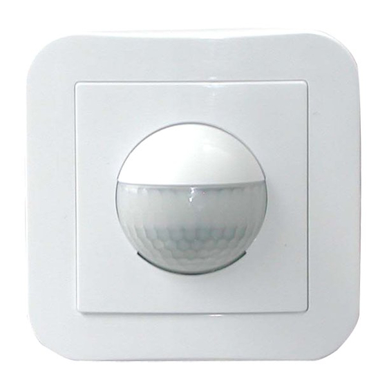
1. Product information
•
Wall-mounted occupancy detector
•
2 switching channels (channel 1 to the switch of light,
channel 2 potential free 3A for device control)
•
Available as Master
•
Extension of the coverage area by slave devices are
possible
•
Manual switching via externally push-button possible
•
NEW: Integrated acoustic sensor
•
Other functions can be adjustable by remote control.
2. Operation
The presence detector controls the light automatically according
to people present (movements) and the ambient brightness.
The integrated light sensor constantly measures the ambient light
and compares it with the brightness level on the detector. If the
ambient light is sufficient, lighting will not be switched..
If the ambient light level is below the brightness level, a move-
ment activated the lighting in the room.
The detector switch the light off instead of a person, if there is
enough natural light for 15 min. or until the follow-up time do
not recognized any movement in the room.
In addition to movement detection, the device is also equipped
with an adjustable acoustic sensor, the follow-up time extended
automatically when sound is detected. For switching on a
detected movement is always required. The acoustic sensor stays
during the follow-up time and 9 seconds after the lights turn off
active.
3. Safety information
Work on the 110-240 V mains supply may only be
carried out by qualified professionals or by instructed
!
persons under the direction and supervision of quali-
fied skilled electrical personnel in accordance with
electrotechnical regulations.
Disconnect supply before installing!
This device is not suitable for disconnection.
4. Mounting
Disconnect mains supply.
Sensor insert
(A)
Mounting screws
(B)
Blinds for the exclusion of interference sources
(C)
(Animals, small children ...)
Frame
(D)
Cover
(E)
Cover cap
(F)
In Master-/Slave-operation the master device must always
!
be installed at the site with less daylight.
®
Indoor 180-M-2C
Install the unit in a protected position,
for wall mounting at a height of 1,10 m
C
to 2,20 m.
M
Y
CM
MY
1m
CY
Minimum distance to lighting being
CMY
controlled, to the front or to the side of
the unit: 1m
K
Inappropriate installation or use will
interfere with trouble-free operation or
lead to damage to the unit.
Suitable for installation in a 60 mm flush-
mounted box. The cable inlet should
be vertical.
5. Hardware configuration
Position Potentiometer's and LED's
(B)
(C)
(A)
Potentiometer (A): Potentiometer Brightness setting
Potentiometer (B): Potentiometer Acoustic sensor
Potentiometer (C): Potentiometer Follow-up time Channel II
Potentiometer (D): Potentiometer Follow-up time Channel I
LED I:
green
LED II: red
LED III: white
LED IV: red (Acoustic sensor)
C
M
Y
CM
MY
CY
CMY
K
DIP-switch function
DIP 1
Normal mode
DIP 2
LED ON
DIP 3
Fully automatic mode
(VA)
6. Self test cycle/Startup behavior
The product enters an initial 60-second self-test cycle, when the
supply is first connected. During this time the device does not
120 60 50
respond to movement and stays on (INI-ON or INI-OFF).
A
40
30
15
5
10
7. Putting into operation / Settings
120 60 50
A
16 10
40
5
30
2
15
5
1
10
TEST
30
15
16 10
5
2000
2
1200
1
600
TEST
30
15
200
40
(D)
2000
1200
600
200
40
III IV
II
I
120 60 50
A
40
30
15
5
10
16 10
5
2
1
TEST
30
15
2000
1200
600
200
40
I
I I
I I I
Corridor mode
LED OFF
Semi automatic mode
(HA)
Follow-up time for light control
The time can be set infinitely variably between
15 sec and 30 minutes.
Symbol TEST:
Test mode
Every movement switches on the light for a period
of 2 second, switching it off for a period of 2
seconds.
Twilight-switch
The switch-on value for the light can be set at be-
tween 10 and 2000 Lux. Using the rotary control,
the luminance set points can be set as desire
Symbol : Night-time operation
Symbol
: Daytime operation
Determine the current brightness value
Set potentiometer 2 in position
TEST.
The green LED glows continuously, as soon as
the value of potentiometer 1 exceeds the current
measured brightness value.
Follow-up time for device control
The follow-up time can be set infinitely variably at
between 5 and 120 minutes. From a set period of
>15 minutes, the delay is active.
This is about 5 minutes.
If there are no further movements detected in this
time, the delay time restarts.
Symbol
: Impuls = 2.5 s
Symbol A:
Alarm impuls = 2 s
Alarm impuls
To initiate an alarm impuls, there must be recog-
nized 3 movements, distributed over a period of 9
seconds
Acoustic sensor
The sensitivity of the acoustic sensor is infinitely ad-
justable with the rotary control (Left position = max.
sensitivity, Right position = acoustic sensor of).
The response of the acoustic sensor is signaled
via LED IV.
Dip switch
NORM/CORR: Activate or deactivate the cor-
ridor function
LED ON/OFF: Activate or deactivate the LED
function display
VA/HA: Activate or deactivate the full or
semi-automatic.
EN
d.
Advertisement
Table of Contents

Related Manuals for B.E.G. LUXOMAT Indoor 180-M-2C


Summary of Contents for B.E.G. LUXOMAT Indoor 180-M-2C
- Page 1 LUXOMAT ® Indoor 180-M-2C Installation and Operating Instruction for B.E.G. - Occupancy detector Indoor 180-M-2C 1. Product information • Wall-mounted occupancy detector • 2 switching channels (channel 1 to the switch of light, Install the unit in a protected position, channel 2 potential free 3A for device control) for wall mounting at a height of 1,10 m •...
- Page 2 7.1 Mode 9. Range 13. LED-functional indicators Semi-Automatic (HA) / Automatic (VA) LED function indicators after each mains recovery (60sec. Automatic initialisation period) The Indoor 180-M-2C is set to Automatic as its factory setting. 1,10 -2,20 m Operating state LED function indicators In Automatic mode, the light must always be turned on via the switch.
- Page 3 B.E.G. B.E.G. B.E.G. LUXOMAT LUXOMAT LUXOMAT ® ® B.E.G. ® IR-PD-2C IR-PD-1C LUXOMAT ® PD-2C 27BUT-BEG LAB2239 14. Settings by remote control when open The “Test“ push button can be used to set the LED ON/ 16. Key functions in closed state PD-2C 32BUT-BEG LAB2238 OFF function.
- Page 4 Except of the INI ON/OFF setting, the detector will be reset to factory setting or the setting of the potentionmeter. Pushing the "RESET" button on the remote control, in opened mode, will delete all of the values which was set by the remote control (beside of INI ON/OFF) and set the detector back to it‘s factory reset.
Need help?
Do you have a question about the LUXOMAT Indoor 180-M-2C and is the answer not in the manual?
Questions and answers