
Related Manuals for Advantech EPC-S101


Summary of Contents for Advantech EPC-S101
- Page 1 User Manual EPC-S101 Slim Type Embedded Barebone System with Intel N3000 & X5- E8000 3.5” SBC...
- Page 2 No part of this manual may be reproduced, copied, translated or transmitted in any form or by any means without the prior written permission of Advantech Co., Ltd. Information provided in this manual is intended to be accurate and reliable. How- ever, Advantech Co., Ltd.
- Page 3 Because of Advantech’s high quality-control standards and rigorous testing, most of our customers never need to use our repair service. If an Advantech product is defec- tive, it will be repaired or replaced at no charge during the warranty period. For out- of-warranty repairs, you will be billed according to the cost of replacement materials, service time and freight.
- Page 4 Increase the separation between the equipment and receiver. Connect the equipment into an outlet on a circuit different from that to which the receiver is connected. Consult the dealer or an experienced radio/TV technician for help. EPC-S101 User Manual...
- Page 5 Technical Support and Assistance Visit the Advantech web site at www.advantech.com/support where you can find the latest information about the product. Contact your distributor, sales representative, or Advantech's customer service center for technical support if you need additional assistance. Please have the following information ready before you call: –...
- Page 6 CAUTION: Always ground yourself to remove any static charge before touching the motherboard, backplane, or add-on cards. Modern electronic devices are very sensitive to static electric charges. As a safety precaution, use a grounding EPC-S101 User Manual...
- Page 7 The sound pressure level at the operator's position according to IEC 704-1:1982 is no more than 70 dB (A). DISCLAIMER: This set of instructions is given according to IEC 704-1. Advan- tech disclaims all responsibility for the accuracy of any statements contained herein. EPC-S101 User Manual...
- Page 8 N3060 EPC- Intel Atom S101AQ X5-E8000 -S0A1 Packing List Part Number Description 1 x EPC-S101 1 x Startup Manual 2190000902 1 x Warranty Card 968EMLRMP1 1 x RMM package 1700026499-01 1 x M cable SATA 22P/SATA 7P+1*4P-2.5 10cm 1700009001 1 x A Cable JACK/1*2P-5.0 4.5CM C=R B 1990019498N020 1 x Thermal-Pad 59x19.5x1.5 XR-HL K=1.2 TP Apus-...
-
Page 9: Table Of Contents
3.1.7 System I/O Ports................. 47 3.1.8 1st MB memory map..............47 3.1.9 Interrupt Assignments ..............48 Appendix A Appendix A Programming GPIO ..49 GPIO Register..................50 Appendix B Watchdog Timer ........51 Programming the Watchdog Timer ............52 EPC-S101 User Manual... - Page 10 EPC-S101 User Manual...
-
Page 11: Chapter 1 General Information
Chapter General Information... -
Page 12: Overview
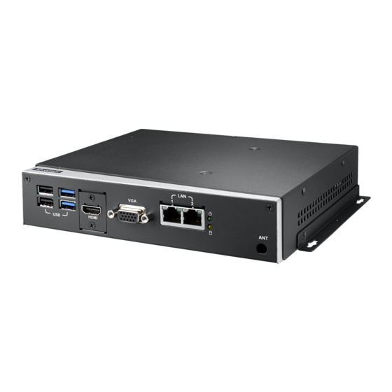
Overview EPC-S101 is a thin design and multi-function bare-bone chassis for space-limited solutions. EPC-S101 measures only 188 x 39 x 150 mm, less than 1U height. This slim, fanless system provides 6 USB ports, 4 COM ports (RS-232/422/485), 2 gigabit Ethernet ports, 1 HDMI, 1 VGA, 8-bit Digital I/O port, and audio jack w/ Mic in, line out and line out ports ready for use. -
Page 13: I/O And Function
Storage: 60° C @ 95% relevant humidity, non-condensing Vibration: With mSATA/SSD: 3 Grms, IEC 60068-2-64, random, 5 ~ 500 Hz, 1 hr/3-axis Shock: With mSATA/SSD: 30G, IEC 60068-2-27, half sine, 11 ms duration EMC: CE/FCC Class B EPC-S101 User Manual... -
Page 14: Mechanical
Dimensions: 188 x 39 x 150 mm Weight: 950g 1.2.6 Software Support OS Support: Windows 7/8.1/10, WES7, Linux, VxWorks (optional by request) Software API: Advantech iManager and WISE- PaaS/RMM - Remote Device Management technology Mechanical Specification EPC-S101 User Manual... -
Page 15: Chapter 2 Hardware Configuration
Chapter Hardware Configuration... -
Page 16: Introduction
HDMI link supports resolutions up to 1920 x 1200 @ 60 Hz. 2.2.1.3 VGA Connector EPC-S101 provides an integrated 15-pin female VGA digital video interface, which supports up to 1920 x 1200 @ 60 Hz. Please refer to Table 2.10 for its pin assign- ments. - Page 17 2.2.1.6 Ethernet Connector (LAN) EPC-S101 is equipped with 2 Ethernet controllers that are fully compliant with IEEE 802.3u 10/100/1000 Mbps CSMA/CD standards. The Ethernet port provides a stan- dard RJ-45 jack connector with LED indicators on the front side to show its Active/ Link status (Green LED) and Speed status (Yellow LED).
- Page 18 Set Parameters of Serial Port 2 (COMB). Serial Port 3 Configuration Set Parameters of Serial Port 3 (COMC). Serial Port 4 Configuration Set Parameters of Serial Port 4 (COMD). 2.2.1.11 Audio x 1 set ALC892-CG supports (Line out, Line-in, Mic-in ) EPC-S101 User Manual...
-
Page 19: Internal Connectors
2.2.2 Internal Connectors 2.2.2.1 Connector Location Ba ery (CN33) SATA PWR SATA (CN21) SIM (CN20) Mini-PCIe (CN19) mSATA (CN18) EPC-S101 User Manual... - Page 20 2.2.2.2 Battery (CN33) CN33 Battery Part Number 1655902032 Footprint WHL2V-125 Description WAFER BOX 2P 1.25mm 180D(M) DIP 53047-0210 Pin Name 2.2.2.3 SATA (CN21) CN21 SATA Part Number 1654011616-01 Footprint SATA_7P_WATF-07DBN6SB1U Description Pin Name EPC-S101 User Manual...
- Page 21 2.2.2.4 Mini PCIE (CN19) CN19 Mini PCIE Part Number 00A00000770 Footprint MINIPCIE_HALF_PICO_ITX Description Pin Name +1.5V SMB_CLK PETn0 SMB_DAT PETp0 USB D- USB D+ +3.3VSB +3.3VSB +1.5V +3.3VSB EPC-S101 User Manual...
- Page 22 2.2.2.5 SIM (CN20) CN20 Part Number 1654010809-01 Footprint SIM_6P_5210622-SINR03 Description SIM card conn. 6p 2.54mm 90D(F) SMD 5210622-SINR Pin Name UIM_PWR UIM_RESET UIM_CLK UIM_VPP UIM_DATA EPC-S101 User Manual...
- Page 23 2.2.2.6 mSATA (CN18) CN18 Mini PCIE Part Number 00A00000770 Footprint MINIPCIE_HALF_PICO_ITX Description Pin Name +1.5V SMB_CLK PETn0 SMB_DAT PETp0 USB D- USB D+ +3.3VSB +3.3VSB +1.5V +3.3VSB EPC-S101 User Manual...
-
Page 24: Installation
Remove the four nylon snap rivets. Screw the HDD with four screws (M3x4L) on the top case. Before screwing back the top cover, replace the thermal pad with substitutes on the inner side of the top cover. EPC-S101 User Manual... -
Page 25: Msata/Mini Pcie/Sim Module Installation (Option)
2.3.2 mSATA/Mini PCIe/SIM module Installation (Option) Unscrew four screws (M3x4L) to remove the bottom cover. Install the SIM card, mSATA or Mini PCIe module. Screw the mSATA or Mini PCIe cards with M2X5L screws. EPC-S101 User Manual... -
Page 26: Wall Mount Bracket Installation (Option)
2.3.3 Wall Mount Bracket Installation (Option) Loosen four side screws of the top case (M3x4L) and screw back with the wall mount bracket. Screw down the four wall mount screws (M3x8L) to the table. EPC-S101 User Manual... -
Page 27: Din Rail Bracket Installation (Option)
Loosen the four din rail screws (M3x4L) on the back case. Screw back the din rail bracket with the din rail screws. 2.3.5 VESA Mount Installation (Option) Unscrew the four VESA Mount screws (M4x8L). Screw back the VESA Mount screws with your mounting surface. EPC-S101 User Manual... - Page 28 EPC-S101 User Manual...
-
Page 29: Chapter 3 Bios Settings
Chapter BIOS Settings... - Page 30 With the AMIBIOS Setup program, you can modify BIOS settings and control the var- ious system features. This chapter describes the basic navigation of the EPC-S101 BIOS setup screens. AMI BIOS ROM has a built-in Setup program that allows users to modify the basic system configuration.
-
Page 31: Entering Setup
BIOS supports your CPU. If there is no number assigned to the patch code, please contact an Advantech application engineer to obtain an up-to-date patch code file. This will ensure that your CPU‘s system status is valid. -
Page 32: Advanced Bios Features Setup
3.1.2 Advanced BIOS Features Setup Select the Advanced tab from the EPC-S101 setup screen to enter the Advanced BIOS Setup screen. You can select any of the items in the left frame of the screen, such as CPU Configuration, to go to the sub menu for that item. You can display an Advanced BIOS Setup option by highlighting it using the <Arrow>... - Page 33 OS. ACPI Sleep State Select the highest ACPI sleep state the system will enter when the SUSPEND button is pressed. Lock Legacy Resources Enable or disable Lock of Legacy Resources EPC-S101 User Manual...
- Page 34 This page displays all information about system Temperature/Voltage/Current. Power Saving Mode This item allows users to set board’s power saving mode when off. Watch Dog Timer This item allows users to select EC watchdog timer. EPC-S101 User Manual...
- Page 35 3.1.2.3 S5 RTC Wake Settings Wake system from S5 Enable or disable System wake on alarm event. Select FixedTime, system will wake on the hr:min:sec specified. EPC-S101 User Manual...
- Page 36 Serial Port Console Redirection Console Redirection This item allows users to enable or disable console redirection for Microsoft Windows Emergency Management Services (EMS). Console Redirection This item allows users to configuration console redirection detail settings. EPC-S101 User Manual...
- Page 37 3.1.2.5 CPU Configuration Limit CPUID Maximum Disabled for Windows XP. Intel Virtualization Technology When enabled, a VMM can utilize the additional hardware capabilities provided by Vanderpool Technology. Power Technology Enables power management features. EPC-S101 User Manual...
- Page 38 3.1.2.6 PPM Configuration CPU C state Report Enable/Disable CPU C state report to OS. Max CPU C-state This option controls Max C state that the processor will support. EPC-S101 User Manual...
- Page 39 SATA Interface Speed SATA Interface Speed Support Gen1, Gen2 or Gen3. Aggressive LPM Support Enables PCH to aggressively enter link power state. Port 1 / Port 2 Enable / disable Serial ATA Port 1 / Port 2. EPC-S101 User Manual...
- Page 40 3.1.2.8 Network Stack Configuration Network Stack Enable/Disable UEFI Network Stack. EPC-S101 User Manual...
- Page 41 Storage Controls the execution of UEFI and Legacy Storage OpROM. Video Controls the execution of UEFI and Legacy Video OpROM. Other PCI devices Determines OpROM execution policy for devices other than Network, Storage, or Video. EPC-S101 User Manual...
- Page 42 Maximum time the device will take before it properly reports itself to the Host Controller. 'Auto' uses a default value: for a Root port it is 100 ms, for a Hub port the delay is taken from Hub descriptor. EPC-S101 User Manual...
- Page 43 3.1.2.11 Security Configuration TXE HMRFPO Disable Host ME Region Flash Protection Override. EPC-S101 User Manual...
- Page 44 Set Parameters of Serial Port 1 Serial Port 2 Configuration Set Parameters of Serial Port 2 Serial Port 3 Configuration Set Parameters of Serial Port 3 Serial Port 4 Configuration Set Parameters of Serial Port 4 EPC-S101 User Manual...
-
Page 45: Chipset Configuration
3.1.3 Chipset Configuration North Bridge Details for North Bridge items. South Bridge Details for South Bridge items. EPC-S101 User Manual... - Page 46 3.1.3.1 North Bridge Intel IGD Configuration Config Intel IGD Settings. Graphics Power Management Control Graphics Power Management Control Options. Max TOLUD Maximum Value of TOLUD. EPC-S101 User Manual...
- Page 47 Select DVMT 5.0 Pre-Allocated (Fixed) Graphics Memory size used by the Internal Graphics Device. DVMT Total Gfx Mem Select DVMT 5.0 Total Graphic Memory size used by the Internal Graphics Device. Aperture Size Select the Aperture Size. GTT Size Select the GTT Size EPC-S101 User Manual...
- Page 48 3.1.3.3 Graphics Power Management Control RC6 Render Standby) Check to enable render standby support. EPC-S101 User Manual...
- Page 49 Azalia HD Audio Options. USB Configuration USB Configuration Settings. PCI Express Configuration PCI Express Configuration settings. OS Selection Select target OS. Windows 8: For UEFI OS (Windows 8 and above.). Windows 7: For Legacy OS. EPC-S101 User Manual...
- Page 50 RTC Lock Enable or disable bytes 38h-3Fh in the upper and lower 128-byte bank of RTC RAM lockdown. BIOS Lock Enable/Disable the BIOS Lock Enable feature. Global SMI Lock Enable or Disable SMI Lock. EPC-S101 User Manual...
- Page 51 3.1.3.6 Azalia Configuration Audio Controller Control Detection of the Azalia device. Disabled = Azalia will be unconditionally disabled. Enabled = Azalia will be unconditionally Enabled. Azalia HDMI Codec Enable/Disable internal HDMI codec for Azalia EPC-S101 User Manual...
- Page 52 3.1.3.7 USB Configuration USB2 PHY Power Gating Configure USB2 PHY Power Gating. USB3 PHY Power Gating Configure USB3 PHY Power Gating. EPC-S101 User Manual...
- Page 53 PCIE Wake Enable / disable PCIE to wake the system from S5. Onboard LAN1/LAN2 Controller Select to Enable / Disable onboard LAN1/LAN2 controller. LAN Option ROM Enabled / Disabled onboard LAN’s PXE option ROM. EPC-S101 User Manual...
-
Page 54: Security
To access the sub menu for the following items, select the item and press <Enter>: Change Administrator / User Password Select this option and press <ENTER> to access the sub menu, and then type in the password. EPC-S101 User Manual... -
Page 55: Boot
Enables or disables Fast Boot with initialization of a minimal set of devices required to launch the active boot option. Has no effect for BBS boot options. New Boot Option Policy Controls the placement of newly detected UEFI boot options. EPC-S101 User Manual... -
Page 56: Save & Exit
This item allows you to save the changes done so far as user defaults. Restore User Defaults This item allows you to restore the user defaults to all the options. Boot Override Boot device select can override your boot priority. EPC-S101 User Manual... -
Page 57: System I/O Ports
Addr. Range (Hex) Device A0000h - BFFFFh Intel® HD Graphics A0000h - BFFFFh PCI Bus C0000h - DFFFFh PCI Bus E0000h - FFFFFh PCI Bus 90400000 – 905FFFFF Intel® Trusted Execution Engine Interface E0000000 - FEFFFFFF System resources EPC-S101 User Manual... -
Page 58: Interrupt Assignments
IRQ5 Communications Port (COM3) / iManager WatchDog IRQ IRQ6 Available IRQ7 Communications Port (COM4) IRQ8 Internal RTC or HPET IRQ9 Microsoft ACPI-Compliant System IRQ10 Available IRQ11 Available IRQ12 Available IRQ13 Numeric data processor IRQ14 SATA controller IRQ15 SATA controller EPC-S101 User Manual... -
Page 59: Appendix A Appendix A Programming Gpio
Appendix Appendix A Programming GPIO... -
Page 60: Gpio Register
GPIO Register GPIO Byte Mapping H/W Pin Name GPO0 BIT0 BIT1 GPO1 GPO2 BIT2 BIT3 GPO3 GPI0 BIT4 BIT5 GPI1 BIT6 GPI2 GPI3 BIT7 Note: For details, please refer to Software API user manual below. Link: http://ess-wiki.advantech.com.tw/view/SW_Service/API/SUSI4.0_USER_MANUAL EPC-S101 User Manual... -
Page 61: Appendix B Watchdog Timer
Appendix Watchdog Timer... -
Page 62: Programming The Watchdog Timer
Trigger Event Note (BIOS setting default disable)** Power button event Power Off Support Support H/W Restart External WDT ** WDT new driver support automatically selects available IRQ. For details, please refer to Software API User Manual Link: http://ess-wiki.advantech.com.tw/view/SW_Service/API/SUSI4.0_USER_MANUAL EPC-S101 User Manual... - Page 63 EPC-S101 User Manual...
- Page 64 No part of this publication may be reproduced in any form or by any means, electronic, photocopying, recording or otherwise, without prior written permis- sion of the publisher. All brand and product names are trademarks or registered trademarks of their respective companies. © Advantech Co., Ltd. 2017...
Need help?
Do you have a question about the EPC-S101 and is the answer not in the manual?
Questions and answers