Delfield UC4048P Specifications, Installation, Operation & Maintenance Manual
Compact refrigerators
Hide thumbs
Also See for UC4048P:
Table of Contents
Advertisement
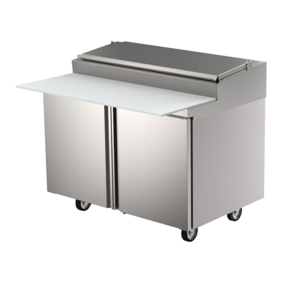
Fresh Solutions, Fit For You
Compact Refrigerators
4400 Series
Specifications, Installation, Operation & Maintenance Manual
This manual is updated as new information and models are released.
Visit our website for the latest information.
Caution
,
Read this instruction before operating this equipment.
Original Document
Part Number: 9295093A 02/21
Advertisement
Table of Contents

Related Manuals for Delfield UC4048P


Summary of Contents for Delfield UC4048P
- Page 1 Fresh Solutions, Fit For You Compact Refrigerators 4400 Series Specifications, Installation, Operation & Maintenance Manual This manual is updated as new information and models are released. Visit our website for the latest information. Caution Read this instruction before operating this equipment. Original Document Part Number: 9295093A 02/21...
- Page 2 Safety Notices Warning This product contains chemicals known to the State of Warning California to cause cancer and/or birth defects or other Read this manual thoroughly before operating, installing reproductive harm. Operation, installation, and servicing or performing maintenance on the equipment. Failure of this product could expose you to airborne particles to follow instructions in this manual can cause property of glasswool or ceramic fibers, crystalline silica, and/...
-
Page 3: Table Of Contents
Table of Contents Section 1 General Information Serial Number Information ....................4 Warranty Information......................4 Regulatory Certifications ....................4 Model Numbers ........................ 4 Section 2 Installation Location ..........................6 Weight of Equipment ......................7 Clearance Requirements ....................8 Dimensions ........................8 Capacity .......................... -
Page 4: General Information
4427NP-8 when calling for parts or service. 4427NP-9M 4427NP-12M One Door Mega Top Warranty Information 4432NP-12M 4448NP-6 Visit www.delfield.com/warranty to: 4448NP-8 Two Door Salad Top • Register your product for warranty. 4448NP-12 4448NP-6M • Verify warranty information. 4448NP-12M Two Door Mega Top •... - Page 5 Section 1 General Information Model Description D4464NP-18M Four Drawer Mega Top D4464NP-24M D4472NP-12 Six Drawer Salad Top D4472NP-18 D4472NP-18M D4472NP-24M Six Drawer Mega Top D4472NP-30M Refrigerated Front Breathers With Doors & 4” S/S Backsplash ST4427NP-6 One Door Salad Top ST4427NP-8 ST4448NP-6 ST4448NP-8 Two Door Salad Top...
-
Page 6: Installation
Section 2 Installation The location selected for the equipment must meet the DANGER following criteria. If any of these criteria are not met, select Installation must comply with all applicable fire and another location. health codes in your jurisdiction. • Units are intended for indoor use only. •... -
Page 7: Weight Of Equipment
Section 2 Installation Weight of Equipment Model Ship Weight Refrigerated Front Breathers With Doors & 4” S/S Backsplash Model Ship Weight ST4427NP-6 240lbs (109kg) Refrigerated Front Breathers With Doors ST4427NP-8 4427NP-6 223lbs (101kg) ST4448NP-6 316lbs (143kg) 4427NP-8 240lbs (109kg) ST4448NP-8 4427NP-9M ST4460NP-8 223lbs (101kg) -
Page 8: Clearance Requirements
31.50” (80cm) 36.00” (91cm) • Avoid hot corners and locations near stoves and ovens. D4464NP-16 D4464NP-18M • These cabinets have Delfield’s “front-breathing” design. D4464NP-24M They may be installed flush against a wall or built into a D4472NP-12 counter as required. -
Page 9: Capacity
Section 2 Installation Refrigerated Front Breathers w/ Doors & Raised Rail Prep Table 1/6 Pan Model Shelf Area Base Volume 4448RP 48” (122cm) 31.50” (80cm) 36.00” (91cm) Capacity 4472RP 72” (182cm) 31.50” (80cm) 36.00” (91cm) D4472NP-12 4496RP 96” (244cm) 31.50” (80cm) 36.00” (91cm) D4472NP-18 Refrigerated Front Breathers w/ Drawers &... -
Page 10: Electrical Service
Installation Section 2 Electrical Service RATED AMPERAGES, HORSEPOWER, VOLTAGE & POWER CORD CHART DANGER Maximum 6ft (1.8m) cord with three-pronged plug. Plug into a three-pronged wall outlet for proper grounding of the Check all wiring connections, including factory terminals, cabinet to begin operation. Do not use an adapter to connect before operation. -
Page 11: Drain Connections
Section 2 Installation Drain Connections Voltage, Cycle, NEMA Model H.P. Phase Plug Warning D4472NP-12 D4472NP-18 Moisture collecting from improper drainage can create a D4472NP-18M 115, 60, 1 5-15P slippery surface on the floor and a hazard to employees. D4472NP-24M It is the owner’s responsibility to provide a container or D4472NP-30M outlet for drainage. -
Page 12: Refrigeration
Installation Section 2 Refrigeration Model BTU/Hour Heat of R290 Charge Capacity Rejection Model BTU/Hour Heat of Refrigerated Front Breathers With Doors & 4” S/S Backsplash R290 Charge Capacity Rejection ST4427NP-6 2038 Refrigerated Front Breathers With Doors ST4427NP-8 4427NP-6 ST4448NP-6 2038 1299 4427NP-8 ST4448NP-8... -
Page 13: Level & Stable
Section 2 Installation Level & Stable Changing Pan Height After the cabinet has been placed in the desired location, If additional pan temperature cooling ability is desired, cabinets with legs must be leveled. Level units from front to especially in higher ambient temperature conditions and/ back and from side to side. -
Page 14: Optional Overshelf Installation Instructions
Installation Section 2 If the overshelf was not ordered with the unit: 1. Set the overshelf in-place on the top of the cabinet. 2. Secure with three screws per side of the cabinet (total six screws). Optional Overshelf Installation Instructions If the unit is ordered to have the overshelf: 1. -
Page 15: Heavy Duty Cutting Board Bracket Mounting
Section 2 Installation Standard Heavy Duty Cutting Board Bracket Mounting Supplies Needed • #3 Phillips Screwdriver Parts Included For 27” & 32” Units Description Part No. Left Bracket Varies Right Bracket Varies Screw, pan head 9321519 Screw, flat head 9324092 Fender Washer 9324043 Parts Included For 48”... - Page 16 Installation Section 2 Heavy Duty Cutting Board Bracket Mounting Instructions 3. Install the cutting board onto the brackets. 1. Attach each bracket to the top of the unit with one flat • Make final bracket adjustments so the cutting board head screw (9324092).
- Page 17 Section 2 Installation 4427NP (R290) & 4427N (404) Lid installation Secure The Fixed Cover To The Unit Part # Part Description 9321170 Screw, Thumb, #10-32x.50 MCP00207 Screw, Shoulder, S/S. 8-32 Epoxy Rolling Lid Nylon Spacer 1. Attach the fixed cover to the rear of the unit with two Fixed Cover thumb screws.
-
Page 18: Operation
Section 3 Operation Warning DANGER The operator of this equipment is solely responsible The on-site supervisor is responsible for ensuring that for ensuring safe holding temperature levels for all operators are made aware of the inherent dangers of food items. Failure to do so could result in unsafe food operating this equipment. -
Page 19: Power To Cool
Section 3 Operation Power To Cool Efficient Operation • After the cabinet is connected to the power source it will • Cabinets with pans should be operated with pans in automatically begin operating. place. Operating the cabinet without all pans in place may damage the cabinet. - Page 20 Operation Section 3 THIS PAGE INTENTIONALLY LEFT BLANK Part Number: 9295093A 02/21...
-
Page 21: Maintenance
Section 4 Maintenance Warning DANGER When cleaning interior and exterior of unit, care should It is the responsibility of the equipment owner to perform be taken to avoid the front power switch and the rear a Personal Protective Equipment Hazard Assessment power cord. -
Page 22: Preventing Blower Coil Corrosion
Maintenance Section 4 and do not require the use of tools or an authorized service box. When finished, it should be wiped clean of all food and person. The gaskets are dart style and can be pulled out of debris. the groove in the door. -
Page 23: Quarterly Cleaning
Section 4 Maintenance Quarterly Cleaning Pipe cleaning brushes can be found locally near you. If you notice water accumulation on the inside of the unit, follow the instructions for cleaning the interior condensate pan and exterior drain lines. Note: This cleaning instruction applies to 4400 units produced after July, 2020. -
Page 24: Cleaning The Condenser Coil
Maintenance Section 4 Copper 90° W/ Rubber hose Hinge Screws Remove the clear rubber hose and the copper 90° pipe and inspect/clean any debris. After cleaning, be sure to reinstall the pipe and hose and firmly pack the black PurmaGum back into place to not allow warm air into the unit. - Page 25 Section 4 Maintenance THIS PAGE INTENTIONALLY LEFT BLANK Part Number: 9295093A 02/21...
-
Page 26: Wiring Diagrams
Section 5 Wiring Diagrams Part Number: 9295093A 02/21... - Page 27 Section 5 Wiring Diagrams THIS PAGE INTENTIONALLY LEFT BLANK Part Number: 9295093A 02/21...
- Page 28 DELFIELD 980 SOUTH ISABELLA ROAD, MOUNT PLEASANT, MI 48858 800-733-8821 WWW.DELFIELD.COM ©2019 Welbilt Inc. except where explicitly stated otherwise. All rights reserved. Part Number: 9295093A 02/21...
Need help?
Do you have a question about the UC4048P and is the answer not in the manual?
Questions and answers