
Related Manuals for Texas Instruments DS100BR210EVK


Summary of Contents for Texas Instruments DS100BR210EVK
- Page 1 DS100BR210EVK User's Guide SMA Evaluation Kit User's Guide Literature Number: SNLU157A April 2014 – Revised September 2016...
- Page 2 SNLU157A – April 2014 – Revised September 2016 DS100BR210EVK User Guide SMA Evaluation Kit The DS100BR210EVK – SMA evaluation kit provides a complete high bandwidth platform to evaluate the signal integrity and signal conditioning features of the Texas Instruments signal conditioning products – with Equalization and De-emphasis.
- Page 3 10GE, FC, SAS, SATA 3/6 Gbps (with OOB detection), Infiniband, CPRI, RXAUI, and many others Ordering Information Table 1. DS100BR210EVK Ordering Information DEVICE QUANTITY DS100BR210SQ/NOPB 2000 DS100BR210SQE/NOPB SMA Evaluation Kit: DS100BR210EVK/NOPB SNLU157A – April 2014 – Revised September 2016 DS100BR210EVK User Guide SMA Evaluation Kit Submit Documentation Feedback Copyright © 2014–2016, Texas Instruments Incorporated...
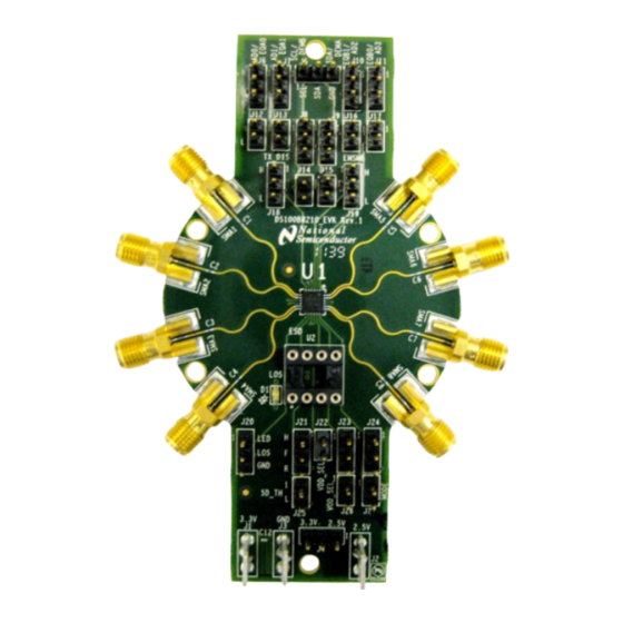
- Page 4 Evaluation Board www.ti.com Evaluation Board Figure 1. DS100BR210EVK Evaluation Board DS100BR210EVK User Guide SMA Evaluation Kit SNLU157A – April 2014 – Revised September 2016 Submit Documentation Feedback Copyright © 2014–2016, Texas Instruments Incorporated...
- Page 5 PIN HEADER CONNECTION Figure 2. 4-Level IO Control on EVK The DS100BR210EVK is shipped ready to use in pin control configuration. As delivered, the EVK will have the following installed jumpers. 1. J4 – 3.3V operation: Use the J1 and J3 connectors to supply 3.3-V power to the EVK.
- Page 6 A serial EEPROM may also be used to configure one or more DS100BR210 devices. This configuration mode is accessed by setting the ENSMB 4-level input to FLOAT. For additional information, please see the device datasheet. DS100BR210EVK User Guide SMA Evaluation Kit SNLU157A – April 2014 – Revised September 2016 Submit Documentation Feedback...
- Page 7 2. De-Emphasis = 0 dB 3. EQ = 2F’h (Default) Additional documentation and device performance is available in the device datasheet. SNLU157A – April 2014 – Revised September 2016 DS100BR210EVK User Guide SMA Evaluation Kit Submit Documentation Feedback Copyright © 2014–2016, Texas Instruments Incorporated...
- Page 8 Figure 3. 6 Gbps Eye Diagram at SCOPE in SETUP1 Figure 4. 10.3125 Gbps Eye Diagram at SCOPE in SETUP1 DS100BR210EVK User Guide SMA Evaluation Kit SNLU157A – April 2014 – Revised September 2016 Submit Documentation Feedback Copyright © 2014–2016, Texas Instruments Incorporated...
- Page 9 Expected Results www.ti.com Figure 5. Jitter Analysis: Breakdown into DJ, RJ, and TJ for 10.3125 Gbps Case SNLU157A – April 2014 – Revised September 2016 DS100BR210EVK User Guide SMA Evaluation Kit Submit Documentation Feedback Copyright © 2014–2016, Texas Instruments Incorporated...
- Page 10 Figure 6. 10.3125 Gbps Eye Diagram at SCOPE in SETUP2 (DE Setting = 000'b) Figure 7. 10.3125 Gbps Eye Diagram at SCOPE in SETUP2 (DE Setting = 110'b) DS100BR210EVK User Guide SMA Evaluation Kit SNLU157A – April 2014 – Revised September 2016 Submit Documentation Feedback Copyright ©...
- Page 11 PLACE AT U1 1287-ST 1287-ST 1287-ST 0.1u Copyright © 2016, Texas Instruments Incorporated Figure 8. DS100BR210EVK Schematic Page 1 SNLU157A – April 2014 – Revised September 2016 DS100BR210EVK User Guide SMA Evaluation Kit Submit Documentation Feedback Copyright © 2014–2016, Texas Instruments Incorporated...
- Page 12 VOD_SEL MODE WM6502-ND WM6502-ND WM6502-ND Copyright © 2016, Texas Instruments Incorporated Figure 9. DS100BR210EVK Schematic Page 2 DS100BR210EVK User Guide SMA Evaluation Kit SNLU157A – April 2014 – Revised September 2016 Submit Documentation Feedback Copyright © 2014–2016, Texas Instruments Incorporated...
- Page 13 RES 0.0 Ω 1/16W 5% 0402 SMD TEXAS DS100BR210SQE/NOPB (24LLP - 4x4mm) INSTRUMENTS 115-43-308-41- ED90197-ND IC SOCKET 8PIN DIP 001000 R36,R38,R39 SNLU157A – April 2014 – Revised September 2016 DS100BR210EVK User Guide SMA Evaluation Kit Submit Documentation Feedback Copyright © 2014–2016, Texas Instruments Incorporated...
- Page 14 • Changed schematic to correct DS100BR210 pin mapping typo ........ • Changed IC BOM component from NSC DS100BR111 to Texas Instruments DS100BR210 Revision History SNLU157A – April 2014 – Revised September 2016 Submit Documentation Feedback Copyright © 2014–2016, Texas Instruments Incorporated...
- Page 15 STANDARD TERMS AND CONDITIONS FOR EVALUATION MODULES Delivery: TI delivers TI evaluation boards, kits, or modules, including any accompanying demonstration software, components, or documentation (collectively, an “EVM” or “EVMs”) to the User (“User”) in accordance with the terms and conditions set forth herein. Acceptance of the EVM is expressly subject to the following terms and conditions.
- Page 16 FCC Interference Statement for Class B EVM devices NOTE: This equipment has been tested and found to comply with the limits for a Class B digital device, pursuant to part 15 of the FCC Rules. These limits are designed to provide reasonable protection against harmful interference in a residential installation.
- Page 17 【無線電波を送信する製品の開発キットをお使いになる際の注意事項】 開発キットの中には技術基準適合証明を受けて いないものがあります。 技術適合証明を受けていないもののご使用に際しては、電波法遵守のため、以下のいずれかの 措置を取っていただく必要がありますのでご注意ください。 1. 電波法施行規則第6条第1項第1号に基づく平成18年3月28日総務省告示第173号で定められた電波暗室等の試験設備でご使用 いただく。 2. 実験局の免許を取得後ご使用いただく。 3. 技術基準適合証明を取得後ご使用いただく。 なお、本製品は、上記の「ご使用にあたっての注意」を譲渡先、移転先に通知しない限り、譲渡、移転できないものとします。 上記を遵守頂けない場合は、電波法の罰則が適用される可能性があることをご留意ください。 日本テキサス・イ ンスツルメンツ株式会社 東京都新宿区西新宿6丁目24番1号 西新宿三井ビル 3.3.3 Notice for EVMs for Power Line Communication: Please see http://www.tij.co.jp/lsds/ti_ja/general/eStore/notice_02.page 電力線搬送波通信についての開発キットをお使いになる際の注意事項については、次のところをご覧くださ い。http://www.tij.co.jp/lsds/ti_ja/general/eStore/notice_02.page SPACER EVM Use Restrictions and Warnings: 4.1 EVMS ARE NOT FOR USE IN FUNCTIONAL SAFETY AND/OR SAFETY CRITICAL EVALUATIONS, INCLUDING BUT NOT LIMITED TO EVALUATIONS OF LIFE SUPPORT APPLICATIONS.
- Page 18 Notwithstanding the foregoing, any judgment may be enforced in any United States or foreign court, and TI may seek injunctive relief in any United States or foreign court. Mailing Address: Texas Instruments, Post Office Box 655303, Dallas, Texas 75265 Copyright © 2015, Texas Instruments Incorporated...
- Page 19 IMPORTANT NOTICE Texas Instruments Incorporated and its subsidiaries (TI) reserve the right to make corrections, enhancements, improvements and other changes to its semiconductor products and services per JESD46, latest issue, and to discontinue any product or service per JESD48, latest issue.
Need help?
Do you have a question about the DS100BR210EVK and is the answer not in the manual?
Questions and answers