
Subscribe to Our Youtube Channel
Related Manuals for Clarke CONTRACTOR CON1050B


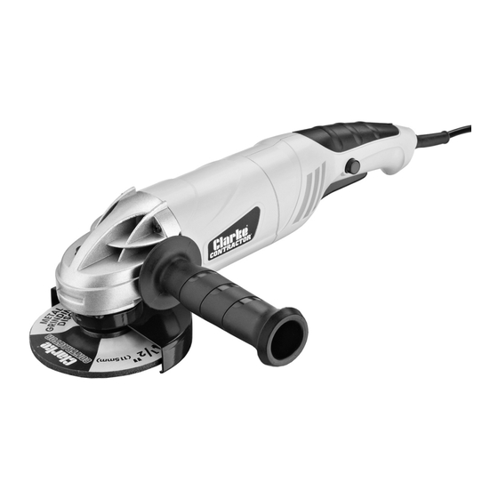
Summary of Contents for Clarke CONTRACTOR CON1050B
- Page 1 1050W ANGLE GRINDER MODEL NO: CON1050B PART NO: 6474010 OPERATING & MAINTENANCE INSTRUCTIONS GC1014...
-
Page 2: Environmental Recycling Policy
Your Angle Grinder has been designed to give long and trouble free service. If, however, having followed the instructions in this booklet carefully, you encounter problems, take the unit to your local CLARKE dealer. GUARANTEE This product is guaranteed against faulty manufacture for a period of 12 months from the date of purchase. -
Page 3: Safety Symbols
SAFETY SYMBOLS The following safety symbols may be found on the machine. Wear ear protection Wear eye protection Falls within WEEE Directive Read instruction manual before use Wear hand protection Parts & Service: 020 8988 7400 / E-mail: Parts@clarkeinternational.com or Service@clarkeinternational.com... -
Page 4: General Safety Rules
GENERAL SAFETY RULES CAUTION: FAILURE TO FOLLOW THESE PRECAUTIONS COULD RESULT IN PERSONAL INJURY, AND/OR DAMAGE TO PROPERTY. WORK ENVIRONMENT 1. Keep the work area clean and well lit. Cluttered and dark areas invite accidents. 2. Do not operate power tools in explosive atmospheres, such as in the presence of flammable liquids, gases or dust. - Page 5 2. Use personal protective equipment. Always wear eye protection. Safety equipment such as dust mask, non-skid safety shoes, hearing protection and a workshop apron capable of stopping small abrasive or workpiece fragments. 3. Avoid accidental starting. Ensure the switch is in the off position before plugging in.
-
Page 6: Angle Grinder Safety Instructions
ANGLE GRINDER SAFETY INSTRUCTIONS 1. Before starting work, always consider the following: The use of hand held angle grinders for grinding and cutting operations can present risks to the user. Full observation of the safety instructions in this user guide is essential. 2. - Page 7 12. Accessories. Only use the recommended accessories. Ensure that the wheels and discs are fitted in accordance with the manufacturer’s instructions. 13. Only use discs that comply with EN12413 or EN13236. Make sure that the disc used is suitable for the no load speed of the angle grinder. See Specifications on page 16.
-
Page 8: Disc Safety Instructions
DISC SAFETY INSTRUCTIONS 1. Disc speed. Check the speed of the disc before fitting to your angle grinder. Never use a disc with a rpm speed less than the rpm speed of your angle grinder. See specification on page 16. 2. -
Page 9: Electrical Connections
ELECTRICAL CONNECTIONS WARNING! Read these electrical safety instructions thoroughly before connecting the product to the mains supply. Before switching the product on, make sure that the voltage of your electricity supply is the same as that indicated on the rating plate. This product is designed to operate on 230VAC 50Hz. - Page 10 Trigger Safety Lock Button Side handle When unpacking, check for damage or shortages etc. Any found should be reported to your CLARKE dealer where the appliance was originally purchased. This CON1050B is supplied with the following loose components: • 2 x Disc Guards •...
-
Page 11: Before Use
BEFORE USE FITTING/ADJUSTING THE DISC GUARD WARNING: MAKE SURE THAT THE ANGLE GRINDER IS SWITCHED OFF AND UNPLUGGED FROM THE MAINS SUPPLY BEFORE FITTING OR REMOVING ANY ACCESSORIES. ENSURE THE CORRECT GUARD IS FITTED FOR THE DISC BEING USED. WARNING: THE DISC GUARD SHOULD BE FITTED SO THAT IT PROVIDES MAXIMUM PROTECTION TO THE USER WHEN IN THE WORKING POSITION. -
Page 12: Fitting The Side Handle
4. Place the grinding disc over the spindle and on top of the inner flange. • If the grinding wheel supplied is a depressed centre type, mount it as shown, i.e.with the depressed centre (printed side) towards the machine. • For standard discs make sure that the raised section of the outer flange is pointing towards the disc. -
Page 13: Operation
OPERATION WARNING: FRAGMENTS FROM A BROKEN/DETACHED DISC CAN CAUSE SERIOUS INJURY. WARNING: WHEN USING CUTTING DISCS, DO NOT STAND DIRECTLY IN LINE WITH THE ROTATING DISC. WARNING: DO NOT PUT SIDEWAYS PRESSURE ON CUTTING DISCS. WARNING: ENSURE THAT THE WORKING POSITION ADOPTED DOES NOT CAUSE OPERATOR FATIGUE WHICH MAY LEAD TO LOSS OF CONTROL OF THE CUTTING DISC AND IMPACT/SNATCH WITH SURROUNDING OBJECTS/ MATERIALS. -
Page 14: Grinding Tips
• The direction of the cutting motion is important. Always feed the cutting disc into the work so that it cuts in an upward direction. If you do not do this It can result in the disc climbing out of the cut in an uncontrolled manner and may lead to loss of control or serious injury. -
Page 15: Suitable Abrasive And Cutting Discs
SUITABLE ABRASIVE AND CUTTING DISCS The following Clarke discs are suitable for use with the CON1050B. Always use the correct disc and guard type for its intended task. Model No Diameter Bore Part No Cutting & Grinding PD1 (plasma) 115mm... -
Page 16: Specifications
SPECIFICATIONS Model Number CON1050B Dimensions (L x W x H) 362 x 137 x 105 mm Weight 2.3 kg Input Power 1050 W Disc Diameter 115 mm Disc Bore 22 mm Spindle Thread Size No Load Speed 11,500 rpm Sound Pressure Level (LpA dB) 93 dB(A) Sound Power Level (LwA dB) 104 dB(A) -
Page 17: Parts List And Diagram
PARTS LIST & DIAGRAM Parts & Service: 020 8988 7400 / E-mail: Parts@clarkeinternational.com or Service@clarkeinternational.com... - Page 18 PARTS LIST & DIAGRAM Description No Description Outer Flange Screw Cutting/Grinding Disc Retaining Plate Inner Flange Round Pin Clamp Screw Motor Fan Square Clamp Nut Motor Armature Machine Screw Spring Washer Housing Screw Flat Washer Motor Stator Spindle Motor Bearing Spindle Housing Motor Housing Bearing...
-
Page 19: Declaration Of Conformity
DECLARATION OF CONFORMITY Parts & Service: 020 8988 7400 / E-mail: Parts@clarkeinternational.com or Service@clarkeinternational.com...
Need help?
Do you have a question about the CONTRACTOR CON1050B and is the answer not in the manual?
Questions and answers