Table of Contents
Advertisement
Quick Links
Advertisement
Table of Contents

Subscribe to Our Youtube Channel
Related Manuals for AIC TB101-PH


Summary of Contents for AIC TB101-PH
- Page 1 TB101-PH Storage Server Barebone User's Manual UM_TB101-PH_v.1_122115...
-
Page 2: Table Of Contents
CONTENTS PREFACE ������������������������������������������������������������������������������������������� i SAFETY INSTRUCTIONS �������������������������������������������������������������������� ii Chapter 1� Prodcut Introduction ������������������������������������������������ 1 1�1 Box Content ����������������������������������������������������������������������������������������1 1.2 Specifications �������������������������������������������������������������������������������������2 1�3 General Information ���������������������������������������������������������������������������3 Chapter 2� Hardware Installation ����������������������������������������������� 6 2�1 Central Processing Unit (CPU) �����������������������������������������������������������6 2�2 System Memory ��������������������������������������������������������������������������������14 2�3 Removing and Installing Chassis Top Cover ���������������������������������18 2�4 Removing and Installing a PSU Module �����������������������������������������19 2�5 Removing and Installing a FAN Module ����������������������������������������20... - Page 3 Copyright © 2015 AIC, Inc� All Rights Reserved� This document contains proprietary information about AIC products and is not to be disclosed or used except in accordance with applicable agreements.
-
Page 4: Preface
AIC shall not be liable for technical or editorial errors or omissions contained herein. The information provided is provided "as is" without warranty of any kind. To the extent permitted by law, neither AIC or its affiliates, subcontractors or suppliers will be liable for incidental, special or consequential damages including downtime cost;... -
Page 5: Safety Instructions
SAFETY INSTRUCTIONS • Before getting started, please read the following important cautions: • All cautions and warnings on the equipment or in the manuals should be noted. • Most electronic components are sensitive to electrical static discharge. Therefore, be sure to ground yourself at all times when installing the internal components. - Page 6 • product, voltage and current marked on the product’s electrical ratings label. The voltage and current rating of the cord should be greater than the voltage and current rating marked on the product. • If the equipment is not used for a long time, disconnect the equipment from mains to avoid being damaged by transient over-voltage.
-
Page 7: Chapter 1� Prodcut Introduction
• Enclosure( Power supply, fan, 2 x 2.5'' HDD tray included) • 2.5’’ HDD Tray • Power cord • Screws kit x 1set • Slide rail x 1set ♦ PACKAGE CONTENT MAY VARY PER REGION. TB101-PH User's Manual... -
Page 8: 1.2 Specifications
Chapter 1 Product Introduction 1.2 Specifications... -
Page 9: 1�3 General Information
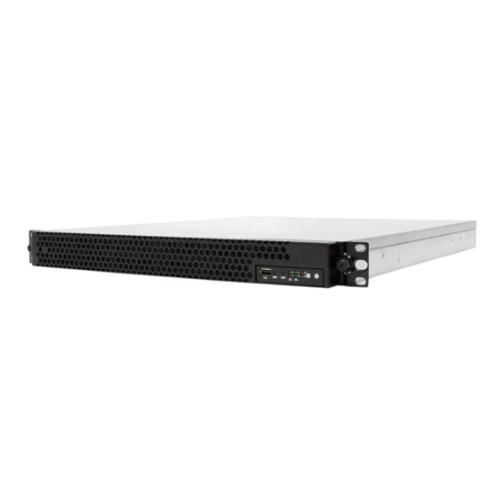
Chapter 1 Product Introduction 1�3 General Information TB101-PH is a 1U Storage Server Barebone with Motherboard Phoenix and MAX IO Riser Card design for up to 2 x PCIe add-on card and 2 x 2.5”HDD hot swap Bays at front and HDD Backplane. - Page 10 Chapter 1 Product Introduction • Rear Panel AC 650W 1+1 redundant power supply 4 x RJ45 ports TB101-PH User's Manual...
- Page 11 Chapter 1 Product Introduction • Major Components AIC Server Board Phoenix 4 x PCIe Add-on card 2 x PCIe Add-on cards AC 650W 1+1 redundant AC 650W 1+1 redundant power supply power supply 2 x 2.5" hot-swap SAS/ 2 x 2.5" hot-swap SAS/...
-
Page 12: Chapter 2� Hardware Installation
• Proceed to screw 2 and loosen it by giving it two rotations and stop (see letter B). Similarly, loosen screws 3 and 4. Repeat steps A and B by giving each screw two rotations each time until all screws are loosened. • Lift the heatsink straight up (see letter C). TB101-PH User's Manual... - Page 13 2.1.2.1 Unlatch the CPU Load Plate • Push the lever handle labeled “OPEN 1st” (see letter A) down and toward the CPU socket. Rotate the lever handle up. • Repeat the steps for the second lever handle (see letter B). TB101-PH User's Manual...
- Page 14 2.1.2.2 Lift open the Load Plate • Rotate the right lever handle down until it releases the Load Plate (see letter A). • While holding down the lever handle, with your other hand, lift open the Load Plate (see letter B). TB101-PH User's Manual...
- Page 15 The processor must align correctly with the socket opening before installation. DO NOT DROP the processor into the socket. NOTE : When possible, a CPU insertion tool should be used when installing the CPU. TB101-PH User's Manual...
- Page 16 Make sure the load plate tab engages under the socket lever when fully closed. • b.Repeat the steps to latch the locking lever on the other side (see letter C). Latch the levers in the order as shown. TB101-PH User's Manual...
- Page 17 (see letter D). Similarly, engage screws 3 and 4. • Repeat steps C and D by giving each screw two rotations each time until each screw is lightly tightened up to a maximum of 8 inch-lbs torque (see letter E). CAUTION: Do not over-tighten fasteners. TB101-PH User's Manual...
- Page 18 Remove the processor by carefully lifting it out of the socket, taking care NOT to drop the processor and not touching any pins inside the socket. Install the socket cover if a replacement processor is not going to be installed. TB101-PH User's Manual...
- Page 19 Caution - Possible thermal damage. Avoid moving the heatsink after it has contacted the top of the CPU. Too much movement could disturb the layer of thermal compound, causing voids, and leading to ineffective heat dissipation and component damage. TB101-PH User's Manual...
-
Page 20: 2�2 System Memory
Chapter 2 Hardware Installation 2�2 System Memory This server board supports up to twelve DDR4 1333/1600/1866/2133 Registered ECC SDRAM(RDIMM) / Load-Reduced DIMM (LRDIMM). TB101-PH User's Manual... - Page 21 JDIMMD1 JDIMMF0 JDIMMD0 JDIMME1 JDIMMC1 JDIMME0 JDIMMC0 JDIMMG0 JDIMMA0 JDIMMG1 JDIMMA1 JDIMMH0 JDIMMB0 JDIMMH1 JDIMMB1 CPU1 CPU0 JDIMM_G0 JDIMM_A0 8 DIMMs JDIMM_H0 JDIMM_B0 CPU0 CPU1 JDIMM_F0 JDIMM_D0 JDIMM_E0 JDIMM_C0 JDIMMF1 JDIMMD1 JDIMMF0 JDIMMD0 JDIMME1 JDIMMC1 JDIMMC0 JDIMME0 TB101-PH User's Manual...
- Page 22 JDIMM_D0 JDIMM_E0 JDIMM_C0 JDIMMF0 JDIMMD0 JDIMME0 JDIMMC0 JDIMMG0 JDIMMA0 JDIMMG1 JDIMMA1 JDIMMH0 JDIMMB0 CPU1 CPU0 JDIMMH1 JDIMMB1 JDIMM_G0 JDIMM_A0 JDIMM_G1 JDIMM_A1 12 DIMMs JDIMM_H0 JDIMM_B0 CPU0 CPU1 JDIMM_H1 JDIMM_B1 JDIMM_F0 JDIMM_D0 JDIMM_E0 JDIMM_C0 JDIMMF0 JDIMMD0 JDIMME0 JDIMMC0 TB101-PH User's Manual...
- Page 23 2.2.2 DIMM Installation Procedure Unlock a DIMM socket by pressing the retaining clips outward. Insert module vertically and press down until it snaps into place. Note: DIMM notch and socket bump must align as shown. DIMM notch TB101-PH User's Manual...
-
Page 24: 2�3 Removing And Installing Chassis Top Cover
Chapter 2 Hardware Installation 2�3 Removing and Installing Chassis Top Cover 1. Loosen the two thumb screws screwing the front cover on the chassis. 2. Loosen the six screws screwing top cover to the chassis. TB101-PH User's Manual... -
Page 25: 2�4 Removing And Installing A Psu Module
• Pushing the latch • Hold the tray handle • Pull the PSU module tray handle out gently to slides out the PSU module. 2.4.2 Installing a PSU Module • To install PSU module, follow the reverse order. TB101-PH User's Manual... -
Page 26: 2�5 Removing And Installing A Fan Module
) to the right. Hold the FAN lever and firmly pull the FAN out of the server chassis. 2.5.2 Installing a FAN Module • To install FAN module, follow the reverse order. CAUTION : SHUT DOWN THE SYSTEM BEFORE REMOVING THE SYSTEM FANS. TB101-PH User's Manual... -
Page 27: 2�6 Replacing The Pcie Card And Riser Assembly
1. Unfasten the two screws securing the bracket to the chassis. 2. Unfasten the two screws securing the card retainer to the chassis. Card Retainer Bracket 3. Disconnect the card from the Riser Card Assembly. Pull the PCIe Card rightward and out of the chassis. TB101-PH User's Manual... - Page 28 Chapter 2 Hardware Installation 3. Disconnect the card from the Riser Card Assembly. Pull the PCIe Card rightward and out of the chassis. TB101-PH User's Manual...
-
Page 29: 2�7 Tool-Less Blade Slide Installation Introduction
Chapter 2 Hardware Installation 2�7 Tool-less Blade Slide Installation introduction 1. Pull on the ‘’Front-Release’’to unlock the inner channel from the Slide Assembly. 2. Release the Detent-Lock and push Middle Channel inwards to retract Middle Channel. TB101-PH User's Manual... - Page 30 Chapter 2 Hardware Installation Optional: Remove Metal Spacer for Aluminium Racks Metal Spacer 3. Aligning the Front Bracket with the Mounting Hole. 4. Push in to assembly the Front Bracket onto the Rack. TB101-PH User's Manual...
- Page 31 Chapter 2 Hardware Installation 5. Now the bracket is fixed onto the Rack. (Optional M6x10L screws are to secure the rails with posts if needed.) 6. Refer to Diagram 3. & 4. to assemble the End Bracket onto the Rack. TB101-PH User's Manual...
- Page 32 Chapter 2 Hardware Installation 7. Assemble the inner channel onto the chassis using thescrews provided. 8. Push the chassis with inner channels into Slide to complete Rack Installation. TB101-PH User's Manual...
-
Page 33: Chapter 3� Motherboard Settings
Placement Rear IO P1 CH2/DIMM0/A0 P0 CH0/DIMM0/A0 P1 CH2/DIMM1/A2 P0 CH0/DIMM1/A2 P1 CH3/DIMM0/A8 P0 CH1/DIMM0/A8 P1 CH3/DIMM1/AA P0 CH1/DIMM1/AA CPU1 CPU0 P1 CH1/DIMM0/A8 P0 CH3/DIMM0/A8 P1 CH0/DIMM0/A0 P0 CH2/DIMM0/A0 P1 Port2 P1 Port3 P0 Port2 P0 Port3 TB101-PH User's Manual... -
Page 34: 3�2 Motherboard Placement
Chapter 3 Motherboard Setting 3�2 Motherboard Placement TB101-PH User's Manual... -
Page 35: 3�3 Motherboard Content List
Chapter 3 Motherboard Setting 3�3 Motherboard Content List TB101-PH User's Manual... -
Page 36: 3�4 Internal Connectors/Jumpers
Chapter 3 Motherboard Setting 3�4 Internal Connectors/Jumpers TB101-PH User's Manual... - Page 37 Chapter 3 Motherboard Setting TB101-PH User's Manual...
- Page 38 Chapter 3 Motherboard Setting TB101-PH User's Manual...
- Page 39 Chapter 3 Motherboard Setting TB101-PH User's Manual...
- Page 40 Chapter 3 Motherboard Setting TB101-PH User's Manual...
- Page 41 Chapter 3 Motherboard Setting TB101-PH User's Manual...
- Page 42 Chapter 3 Motherboard Setting TB101-PH User's Manual...
-
Page 43: 3�5 Leds
Chapter 3 Motherboard Setting 3�5 LEDs 3.5.1 Front Panel LED TB101-PH User's Manual... - Page 44 Chapter 3 Motherboard Setting 3.5.2 Rear Panel LED TB101-PH User's Manual...
- Page 45 Chapter 3 Motherboard Setting 3.5.3 Internal LEDs TB101-PH User's Manual...
-
Page 46: Chapter 4. Bios Configuration And Settings
INSTEAD OF POST MESSAGES. Press ESC to run the setup procedure. Choose the SCU to enter the Setup menu Caution: For the official released version, the last digit of the BIOS Version must end in an "0." TB101-PH User's Manual... - Page 47 Chapter 4 BIOS Configuration and Settings Identify the BIOS Version Load Optimal Default setting Save the setting and exit the BIOS setup utility. TB101-PH User's Manual...
-
Page 48: 4�1 Updating Bios
Press <I> key to post system information Press <F4> key to open POPUP menu 6. Please press <F> key to enter Messiah Flash utility. 7. Follow the instruction until the message “Update Flash successfully” that had been displayed. 8. Reboot system. TB101-PH User's Manual... - Page 49 H2offt-d utility. To use this utility, you must include the flash.bat , H2offt-d. exe, and bin file in the same folder. Please follow the instructions to update whole flash part: Execute flash.bat to update Flash in the DOS environment. Reboot system. TB101-PH User's Manual...
-
Page 50: Chapter 5. Bmc Configuration And Settings
Insert Ethernet LAN cable into the BMC LAN port. There are two methods to setup BMC IP: BMC management port 5�1 Method 1 (Use the BIOS setup) • BIOS SETUP Advanced H2O IPMI configuration BMC configuration IPv4 source Static TB101-PH User's Manual... - Page 51 Chapter 5 BMC Configuration and Settings 2. Input IP address. Set static IP. TB101-PH User's Manual...
- Page 52 Chapter 5 BMC Configuration and Settings 3. Input subnet mask address. TB101-PH User's Manual...
-
Page 53: 5�2 Method 2 (Use A Dos Tool - Syscheck)
5�2 Method 2 (Use a Dos tool - Syscheck) 1. Type : sc –lanset 2. Modify IP setting Note: type 1 for selecting static IP mode or type 2 for selecting DHCP mode. 3. Input IP address TB101-PH User's Manual... - Page 54 Below IP address is an example using a default IP setting. User is allowed to change the IP address for realistic use. 5. Finish BMC IP configuration. Note: Type sc.exe –langet command to obtain BMC IP and MAC address. TB101-PH User's Manual...
-
Page 55: 5�3 Connect To Bmc
Password: admin Note: The default user name and password are in lower-case characters. Note: Users who login with the admin user name and password will have full administrative power. The admin password can be changed after login. TB101-PH User's Manual... - Page 56 Chapter 5 BMC Configuration and Settings 3. Information of firmware. 4. Server Health - Sensor Readings: TB101-PH User's Manual...
- Page 57 Chapter 5 BMC Configuration and Settings 5. Configuration Refer to AIC BMC User Guide for more information on AIC BMC. Mouse Mode setting: For Windows OS environment, set mode to absolute. For Linux OS environment, set mode to relative TB101-PH User's Manual...
- Page 58 Chapter 5 BMC Configuration and Settings 6. Remote Control: Environmental setting: Press “ALT+C” for local and remote OS mouse control switching. TB101-PH User's Manual...
-
Page 59: 5�4 Updating Bmc Firmware
A:>cd SB301C01 A:\ SB301C01>a.bat This is just an example. The latest BMC firmware version is available from the FAE or AIC website. 4. After update BMC firmware, please power off and then power on system. Notes: 1. DO NOT USE EMM386 IN DOS ENVIRONMENT WHEN UPDATING FIRMWARE OR YOU WILL GET A FAIL. -
Page 60: Chapter 6� Technical Support
Chapter 1 Product Introduction Chapter 1 Product Introduction Chapter 6� Technical Support www�aicipc�com • TAIWAN Tel: +886 3 433 9188 Fax: +886 3 287 1818 Email : sales@aicipc�com�tw • CHINA Tel: +86�21�54961421, +86�21�54961422 Fax: Extension: 608 Email Technical Support: support@aicipc�com •...
Need help?
Do you have a question about the TB101-PH and is the answer not in the manual?
Questions and answers