Table of Contents
Advertisement
Quick Links
Advertisement
Table of Contents

Subscribe to Our Youtube Channel
Related Manuals for Leica BIOSYSTEMS SM2010R


Summary of Contents for Leica BIOSYSTEMS SM2010R
- Page 1 Instructions for Use Leica SM2010 R Sliding Microtome Instructions for Use Leica SM2010 R, V 1.4 RevC – 09/2013, English Order No.: 14 0508 80101 RevC Always keep this manual with the instrument. Read carefully before working with the instrument.
- Page 3 Instructions for Use are not to be considered as warranted characteristics of © Leica Biosystems Nussloch GmbH our products. Leica Biosystems Nussloch GmbH Heidelberger Str. 17 - 19 D –69226 Nussloch...
-
Page 4: Table Of Contents
Table of contents Important Information ..........................3 Safety ................................. 4 Safety notes ..............................4 Warnings ............................... 4 Instrument Components and Specifications ..................7 Overview - instrument components ......................7 Technical data .............................. 8 Instrument Setup ............................ 10 Standard delivery ............................10 Site requirements ............................ -
Page 5: Important Information
Important Information Symbols in the text and their meanings • All laboratory personnel designated to operate the Leica instrument must read these Instruc- tions for Use carefully and must be familiar Warnings with all technical features of the instrument appear in a gray box and are marked by before attempting to operate it. -
Page 6: Safety
Safety Be sure to comply with the safety instructions and warnings provided in this chapter. Be sure to read these instructions, even if you are already familiar with the operation and use of other Leica products. Safety notes These Instructions for Use include important This instrument has been built and tested in ac- information related to the operating safety and cordance with the Machinery Directive 2006/42/... - Page 7 Safety Warnings - Safety instructions / warning labels attached to the instrument • Safety notes on the instrument itself, which are marked with a warning triangle, indicate that the correct operating instructions (as defined in these Instructions for Use) must be followed when operating or replacing the item marked.
- Page 8 Safety Integrated safety devices The instrument is equipped with the following safety devices: • Knife guard (14) on the blade/knife Knife sledge holder. locked • Knife sledge locking knob (23) for the knife sledge. Knife sledge locking knob The knife sledge is locked in place us- Knife sledge ing the locking knob (23) that engages is movable...
-
Page 9: Instrument Components And Specifications
Instrument Components and Specifications Overview - instrument components Lever for clamping the blade Clamping lever for lateral displacement Blade holder SE Universal cassettes clamp Knife guard on Setscrew for the blade holder orientation in cutting Quick clamping direction system for holding Specimen cylinder the specimen clamps... -
Page 10: Technical Data
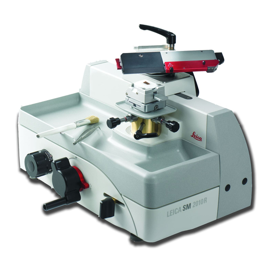
Instrument components and specifications Technical data General Approvals: The instrument-specific marks are located on the name plate. Operating temperature range: 10 °C to +40 °C Relative humidity: max. 80% non-condensing Operating temperature range during storage: + 5 °C to +55 °C Storage humidity: <... - Page 11 Instrument Components and Specifications Instrument specifications • The Leica SM2010 R is a manually operated sliding microtome, designed as a low-maintenance tabletop instrument with roller-guided knife sledges and automatic section thickness feed. • Stable, torsion-free basic design with micrometer feed system in a closed housing, protected from ingress of paraffin waste. • The vertical cross roller bearings have a cover which provides reliable protection from ingress of section waste. • The instrument has an ergonomically optimized specimen head position; the smooth-running knife sledge can be securely locked in 10 mm incre- ments.
-
Page 12: Instrument Setup
Instrument Setup Standard delivery The Leica SM2010 R standard delivery includes: 1 Leica SM2010 R basic instrument ..........14 0508 42258 1 section waste tray ................ 14 0508 42328 1 tool set consisting of ..............14 0508 42983 1 Allen key size 6 ................14 0194 43634 1 Allen key with handle, size 4 ............ -
Page 13: Unpacking
Instrument Setup Unpacking First check the shipment for external damages upon arrival. If it is evident that the shipment was damaged during transport, please make a claim to the carrier immediately. • Open the packaging. • Remove all foam material. • Take out all accessories and the instruction manual. Setup Do not transport the instrument by hold- ing it by moving parts, on the knife sledge, coarse driving wheel or the knob for setting the section thickness. - Page 14 Instrument Setup Horizontal alignment For safe and accurate work, it is important that all instrument feet are in uniform contact with the installation surfaces. The microtome is horizontally aligned at the fac- tory. If a completely level or horizontal surface is not available at the installation site, the instrument must be realigned.
-
Page 15: Assembling The Knife Holder Sn
Instrument Setup Assembling the knife holder SN Installing the intermediate plate 64.1 • Lock the knife sledge (11) in place using the 64.2 locking knob (23) so that it cannot be moved. • The intermediate plate (60) intended for the knife holder SN, is mounted on the mounting table (62) of the knife sledge (11). - Page 16 Instrument Setup Assembling the knife holder SN (continued) Fastening the knife holder The knife holder SN (67) has two bores (64) and thus two different mount- ing positions for different sectioning requirements. 64.1 66.1 64.2 • Press the clamping lever (66) of the knife holder (67) downwards and screw the bottom of the thread (66.
- Page 17 Instrument Setup Assembling the knife holder SN (continued) (Fig. Setting the clearance angle Enlarged detail: • Unscrew the knurled head screw (69). Scale for • Set the required angle with the adjusting lever setting the clearance (70) using the scale for the clearance angle angle. (71). The upper edge (73, red arrow in Fig.
-
Page 18: Assembling The Blade Holder Se
Instrument Setup Assembling the blade holder SE The blade holder SE is designed for conventional disposable blades from all common manufactur- ers. It is available in two models: one for low-profile blades and one for high-profile blades. The blade holder SE has a lateral movement, so that the entire width of the blade can be used. - Page 19 Assembling the blade holder SE (continued) Inserting the blade holder SE The stopper (18) serves for clos- ing the insertion opening (56) for the T-piece in the grooved plate, in order that no sec- tion waste can ac- cumulate there. Fig.
- Page 20 Instrument Setup Assembling the blade holder SE Inclination (declination) (continued) of the blade holder SE • Unscrew the Allen screw (52) at the back of the blade-holder base using an Allen key SW 6. • Turn the blade holder to the required position. 55.1 • Set the required declination (inclination of the blade holder to the cutting direction) on the scale (55.1) at the back of the blade holder (67).
- Page 21 Instrument Setup Assembling the blade holder SE (continued) Adjusting the clearance angle and declination Caution! Always remove the blade before adjust- ing the clearance angle. The knife guard does not provide any protection if you reach into the blade from below (around the blade holder).
- Page 22 Instrument Setup Inserting the universal cassette clamp The object orientation allows for simple position correction of the specimen surface when the specimen is clamped into place. You can use the quick clamping system (29) to hold all the available accessory specimen clamps (for more information, see Chapter 7 "Optional Accessories").
-
Page 23: Operation
Operation Operating elements and their functions 5.1.1 Section thickness setting The section thickness is set by turning the adjust- ing knob (33) on the left side of the microtome. The scaled knob has a notch for each value that can be set. Setting range: 0.5 - 60 µm from 0.5 - 5.0 µm in 0.5 µm increments from 5.0 - 10.0 µm in 1.0 µm increments... -
Page 24: Manual Feed
Operation 5.1.3 Manual feed The lever (35) for the manual feed is at the front right of the instrument. • Each time the lever is pushed or pulled, this causes a feed motion for trimming or section- ing by the value set on the scaled adjusting knob (33). 5.1.4 Automatic feed The position of the adjusting knob (22) determines the point of the knife sledge movement where the... -
Page 25: Directional Fixture For Specimen Clamps
Operation 5.1.5 Directional fixture for specimen clamps All object clamps available as optional accessories can be inserted into the quick clamping device (29) of the directional specimen holder fixture, all object clamps avail- able as optional accessories can be used. The object orientation allows for simple position correction of the specimen surface when the specimen is clamped into place. -
Page 26: Clamping The Specimen In The Universal Cassette Clamp (Ucc)
Operation Clamping the specimen in the universal cassette clamp (UCC) Caution! Always clamp the specimen block BE- FORE clamping the knife. Lock the knife sledge and cover the knife edge / blade edge with the knife guard prior to any manipulation of knife/ blade or specimen, prior to changing the specimen block and during all work breaks! -
Page 27: Clamping A Disposable Blade
Operation Clamping a disposable blade Be very careful when handling micro- tome knives or blades. The cutting edge is extremely sharp and can cause seri- ous injuries! The blade holder has to be installed in the instrument before a blade is inserted! Insert the blade (Fig. -
Page 28: Replacing The Pressure Plate
Operation Replacing the pressure plate The blade holder SE can be converted from use of narrow blades to use of wide blades, and vice versa. To do this, both the pressure plate (48) and the matching insertion aid (57) have to be replaced. To replace them, proceed as follows: • Push the knife guard (14) towards the right and push the lever (46) -
Page 29: Inserting The Knife
Operation Inserting the knife Be very careful when han- dling microtome knives or blades. The cutting edge is extremely sharp and can cause serious injuries! The blade holder has to be installed in the instrument be- fore a blade is inserted! • Lock the knife sledge (11) in place using the locking knob (23). -
Page 30: Sectioning
Operation Sectioning Cutting into the specimen (trimming) For trimming, the specimen feed can be dis- engaged either by turning the coarse driving wheel (36) or by operating the manual feed lever (35). • Hold the knife sledge (11) at the grip (12) and place the sledge behind the specimen. • Pull the knife guard (14) of the blade/knife holder to the right. -
Page 31: Changing The Specimen Or Interrupting Sectioning
Operation Changing the specimen or interrupting sectioning Lock the knife sledge and cover the knife edge with the knife guard prior to any manipulation of knife or specimen head, as well as prior to changing the specimen block and during all work breaks! • Lock the knife sledge and move the specimen clamp far enough down- ward that the new specimen fits below the knife/blade. -
Page 32: Cleaning And Maintenance
Cleaning and maintenance Cleaning the instrument • Always remove the knife or blade before detaching the knife/ blade holder from the instrument! • Always put the knives back into the knife case when not in use! • Never place a knife anywhere with the cutting edge facing up- wards and never try to catch a falling knife! • When using cleaning agents, observe the manufacturer's safety instructions and the laboratory regulations valid in the country of... - Page 33 Cleaning and Maintenance Clean the instrument and outer surfaces • If necessary, the varnished outside surfaces can be cleaned with a mild, commercial household cleaner or soapy water and then wiped with a moist cloth. • To remove paraffin residue, xylene substitutes, e.g. Roth Histol (Roth, Karlsruhe), Tissue Clear (Medite), Histo Solve (Shandon), paraffin oil or paraffin removers, e.g. Paragard (Polysciences) can be used. • For treating varnished surfaces, a commercially available varnish cleanser is recommended.
-
Page 34: Optional Accessories
Optional accessories Ordering information Supermega cassette clamp with adapter, silver ..............14 0508 42634 Universal cassette clamp with adapter, silver ................. 14 0508 42635 HN40 clamp with adapter, silver ....................14 0508 42637 Standard specimen clamp with adapter, silver ................ 14 0508 42632 Dry ice tub with adapter, silver.................... - Page 35 Optional Accessories Supermega cassette clamp, with adapter, silver for mounting in the quick change system for specimen imaging Maximum specimen size: 75 x 52x35 mm (L x W x H) Order No..........14 0508 42634 Fig. 36 Universal cassette clamp (UCC), with adapter, silver for mounting in the quick change system for specimen imaging...
- Page 36 Optional accessories Standard specimen clamp, with adapter, silver for mounting in the quick change system for specimen imaging Maximum specimen size: 79 x 60 mm (L x W) Order No..........14 0508 42632 Fig. 39 Dry ice tub with adapter, silver Order No.
- Page 37 Optional Accessories Blade holder SE, assembly Easily converted from a low-profile to high-profile blade holder by switching the pressure plate. Adjusting the clearance angle using an Allen key. Blade holder declination with scale for reproduc- ible adjustment up to 45°. Safe insertion of the disposable blade using a magnet and insertion aid on the blade holder.
- Page 38 Optional accessories Knife holder SN, assembly for resharpenable knives or blade rails. Blade holder declination with scale for reproducible ad- justment up to 45°. 2 clamping screws for quickly and securely clamping the cutting tool. Safe lateral displacement of the cutting tool for using the entire blade edge.
- Page 39 Optional Accessories Plastic knife guard, for blade rails Order No..........14 0368 33772 Fig. 47 Knife, 16 cm Profile C, steel flat on both sides, for wax and frozen sections. Note: including knife case 14 0213 11140 Order No..........14 0216 07100 Fig.
- Page 40 Optional accessories Leica low-profile disposable blades - Type 819 Length 80 mm, height 8 mm 1 package of 50 pieces Order No..........14 0358 38925 Fig. 52 Leica high-profile disposable blades - Type 818 Length 80 mm, height 14 mm 1 package of 50 pieces Order No.
-
Page 41: Troubleshooting
Troubleshooting In the following table there is a list of the most common problems which can arise while work- ing with the instrument, along with possible causes and troubleshooting procedures. Problem Possible cause Corrective action • The blade is not clamped properly. • Reclamp the blade. 8.1 Possible faults 1. -
Page 42: Warranty And Service
Warranty and Service Warranty Leica Biosystems Nussloch GmbH guarantees that the contractual product delivered has been subjected to a comprehensive quality control procedure based on the Leica in-house testing standards, and that the product is fault- less and complies with all technical specifications and/or characteristics warranted. -
Page 43: Notes
Notes Leica SM2010 R... -
Page 44: Decontamination Certificate (Master)
Dear Customer, Any product that is to be returned to Leica Biosystems or serviced on site, must be cleaned and decontaminated in the appropriate manner. Since it is not possible to decontaminate for prion diseases, such as CJD, BSE, CWD etc., equipment exposed to specimens containing prion diseases cannot be returned to Leica Biosystems for repair. - Page 45 Such equipment must not be returned without the written agreement of Leica Biosystems. Decontamination Certificate (Master) The equipment has been prepared to ensure safe handling/transportation. Whenever possible, please use the original transportation case/box. Important - to avoid refusal of shipment: Place one copy in the unit prior to packaging, or hand it over to the service engineer.
- Page 46 Leica Biosystems Nussloch GmbH Heidelberger Straße 17–19 D– 69226 Nussloch Phone: +49 - (0) 6224 - 143 0 Fax: +49 - (0) 6224 - 143 268 Web: www.LeicaBiosystems.com...
Need help?
Do you have a question about the SM2010R and is the answer not in the manual?
Questions and answers