
Related Manuals for Motorola solutions PELCO Sarix Multi Pro


Summary of Contents for Motorola solutions PELCO Sarix Multi Pro
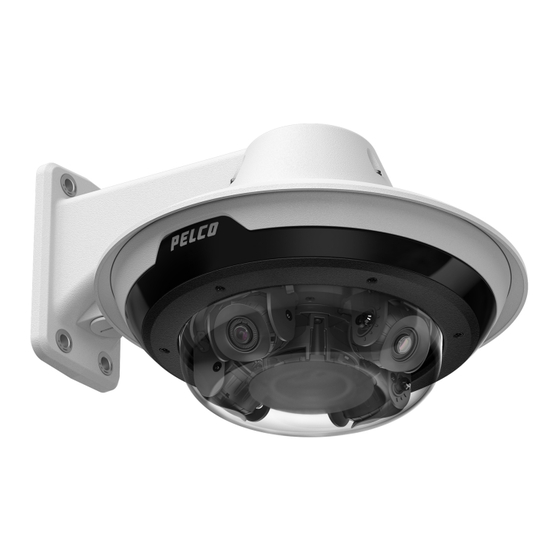
- Page 1 Sarix® Multi Pro Camera Installation Manual Document number: C6715M Publication date: 01/24/22...
-
Page 2: Table Of Contents
Sarix® Multi Pro Camera Installation Manual Table of Contents Overview Camera Module Camera Back View Camera Top View Surface Mount Adapter Pendant Mount Adapter In-Ceiling Mount Adapter Outdoor Dome Cover In-Ceiling Dome Cover Pendant Wall Mount Pendant NPT Mount Preparing the Installation Pre-Deployment In-Box Configuration Pendant Mount Installation Required Tools and Materials... - Page 3 Sarix® Multi Pro Camera Installation Manual Installing the Surface Mount Dome Cover In-Ceiling Mount Installation Camera Package Contents In-Ceiling Mount Installation Steps Preparing the Camera for In-Ceiling Installation (Optional) Cutting the Mounting Hole for the In-Ceiling Mount Adapter (Optional) Attaching the Conduit Cable Entry Cover for Plenum Installations Installing the In-Ceiling Mounting Adapter Connecting Cables (Optional) Configuring microSD Card Storage...
- Page 4 Sarix® Multi Pro Camera Installation Manual Important Safety Information This manual provides installation and operation information and precautions for the use of this device. Incorrect installation could cause an unexpected fault. Before installing this equipment read this manual carefully. Please provide this manual to the owner of the equipment for future reference. This Warning symbol indicates the presence of dangerous voltage within and outside the product enclosure that may result in a risk of electric shock, serious injury or death to persons if proper precautions are not followed.
- Page 5 Sarix® Multi Pro Camera Installation Manual This equipment has been tested and found to comply with the limits for a Class B digital device, pursuant to Part 15 of the FCC rules. These limits are designed to provide reasonable protection against harmful interference in a residential installation.
-
Page 6: Overview
Sarix® Multi Pro Camera Installation Manual Overview Camera Module Camera Back View 1. Lanyard anchor The safety lanyard attaches to the anchor to prevent the camera from falling during installation. 2. IR ring cable connector Accepts IR cable connection to power and control the IR illuminator ring. 3. -
Page 7: Camera Top View
Sarix® Multi Pro Camera Installation Manual Camera Top View 1. Serial number tag Device information, product serial number and part number label. 2. Camera heads The multiple camera heads that can be moved, aimed and focused to monitor different scenes. Note: There may be three or four camera heads depending on your camera model. -
Page 8: Surface Mount Adapter
Sarix® Multi Pro Camera Installation Manual Surface Mount Adapter 1. Lanyard to camera Connects to the lanyard anchor on the camera base. 2. Cable entry hole (rear) An entry hole for the cables required for camera operation. 3. Cable entry hole (side) An entry hole for the cables required for camera operation. -
Page 9: Pendant Mount Adapter
Sarix® Multi Pro Camera Installation Manual Pendant Mount Adapter 1. Alignment tab An alignment tab is used to align with the lanyard clip on the dome cover. 2. Lanyard to dome cover Connects to the lanyard anchor on the dome cover. 3. -
Page 10: In-Ceiling Mount Adapter
Sarix® Multi Pro Camera Installation Manual In-Ceiling Mount Adapter 1. Lanyard to camera Connects to the lanyard anchor on the camera base. 2. Clamps Spring loaded locking mechanisms that secure the camera to the mounting surface. 3. Cable entry hole and conduit cable entry cover An entry hole for the cables required for camera operation. -
Page 11: Outdoor Dome Cover
Sarix® Multi Pro Camera Installation Manual Outdoor Dome Cover 1. Tamper resistant screws Star-shaped captive screws to fix the dome cover to the base. Note: There are 6 captive screws on the dome cover. Only 4 screws are shown in the figure above. -
Page 12: In-Ceiling Dome Cover
Sarix® Multi Pro Camera Installation Manual In-Ceiling Dome Cover 1. Tamper resistant screws Star-shaped captive screws to fix the dome cover to the base. 2. Dome cover notch Notch used to align the dome cover with the mounting adapter clip notch when installing the dome cover. -
Page 13: Pendant Wall Mount
Sarix® Multi Pro Camera Installation Manual Pendant Wall Mount 1. Pendant wall mount Camera mount for walls and other mounting surfaces. 2. Lanyard Connects to the lanyard anchor on the mounting adapter. 3. Tamper resistant screws Star-shaped captive screws to fix the mounting adapter to the pendant wall mount. Note: There are 3 captive screws on the pendant mount. -
Page 14: Pendant Npt Mount
Sarix® Multi Pro Camera Installation Manual Pendant NPT Mount Note: The NPT pipe and NPT-female to NPT-female adapter are not supplied by Pelco and should be sourced separately. However, if you are using the NPT adapter (NPTA-1001), the lock nut is included. -
Page 15: Preparing The Installation Pre-Deployment In-Box Configuration
Sarix® Multi Pro Camera Installation Manual Preparing the Installation Pre-Deployment In-Box Configuration The camera comes equipped with an RJ45 configuration cable pre-installed for users that want to configure camera settings before installing the camera. The RJ45 connector on the configuration cable is accessible through the small flap on the side of the camera box for easy configuration before unpacking the camera. -
Page 16: Pendant Mount Installation
(for in-ceiling cameras). Ensure the camera package contains the following: Pelco Sarix Multi Pro Camera module. A 3- or 4-sensor camera module with 3 MP, 5 MP, or 4K (8 MP) resolution per sensor. Audio, external power, and I/O pigtail cable connector... - Page 17 Sarix® Multi Pro Camera Installation Manual The dome camera must be mounted as instructed below or problems with moisture may arise and will not be covered by the dome camera warranty. 1. Determine where the cables will enter the pendant wall mount. If the cables will be pulled from inside the mounting surface, use the cable entry hole at the rear of the pendant wall mount.
-
Page 18: (Optional) Installing The Npt Mount Adapter
Sarix® Multi Pro Camera Installation Manual 7. Pull the cables through the pendant wall mount. (Optional) Installing the NPT Mount Adapter The dome camera must be mounted as instructed below or problems with moisture may arise and will not be covered by the dome camera warranty. If you are installing the Sarix Multi Pro camera with an NPT adapter (NPTA-1001), the dome camera must be mounted on a 1-1/2”... - Page 19 Sarix® Multi Pro Camera Installation Manual 1. 1. Wrap the thread of the NPT adapter with the supplied thread-sealing tape to create a water tight seal around the camera connection. There should be three to five turns around the entire threaded surface.
-
Page 20: Installing The Pendant Mounting Adapter
Sarix® Multi Pro Camera Installation Manual 4. Pull the cables through the mounting bracket and adapter. Installing the Pendant Mounting Adapter Use the following procedure to mount the pendant adapter (IMD1-PMT) into a pendant wall mount (WLMT- 1001) or NPT mount (NPTA-1001). 1. -
Page 21: Connecting Cables
Sarix® Multi Pro Camera Installation Manual Connecting Cables Refer to the diagrams in the Overview section for the location of the different connectors. To connect the cables required for proper operation, complete the following: 1. Feed the network cable through the gland cap and cable gland. Crimp the RJ-45 cable connector (supplied) to the end of your network cable. - Page 22 Sarix® Multi Pro Camera Installation Manual With IR Ring: 24 VAC ± 10%, 74 VA minimum, or 24 VDC ± 10%, 52 W minimum. Without IR Ring: 24 VAC ± 10%, 37 VA minimum, or 24 VDC ± 10%, 26 W minimum. 3.
-
Page 23: (Optional) Configuring Microsd Card Storage
Sarix® Multi Pro Camera Installation Manual 5. Remove the connector covers from the external power/audio/digital I/O connector and the optional IR illuminator connector. 6. Connect the network cable to the Ethernet port (a) and the external power/audio/digital I/O cable to its connector (b). -
Page 24: Initializing A Camera Username And Password
2. Access the camera’s web interface to enable the onboard storage feature. For more information, see the Pelco Sarix Multi Pro Camera Operations Manual. Initializing a Camera Username and Password Important: You must create a user with administrator privileges before the camera is operational. -
Page 25: Accessing The Live Video Stream
Sarix® Multi Pro Camera Installation Manual Note: If the device cannot obtain an IP address from a DHCP server, it will use Zero Configuration Networking (Zeroconf) to choose an IP address. When set using Zeroconf, the IP address is in the 169.254.0.0/16 subnet. -
Page 26: Aiming The Sarix Multi Pro Camera
Sarix® Multi Pro Camera Installation Manual Aiming the Sarix Multi Pro Camera Reference the camera's live stream as you aim the camera. 1. To aim the camera, adjust each of the available camera heads as required: a. Unlock the rail release tab to move the camera head from side to side. Lock the rail release tab when the camera head is in the desired position. - Page 27 Sarix® Multi Pro Camera Installation Manual After the camera has been mounted into the mounting adapter, install the IR illuminator ring with the Sarix Multi Pro camera base: 1. Mount the IR illuminator ring into the dome cover (IMD1-SPLD1 or IMD1-SPLD0): a.
-
Page 28: Installing The Pendant Mount Dome Cover
Sarix® Multi Pro Camera Installation Manual secure the connection. Installing the Pendant Mount Dome Cover Note: Be careful not to scratch or touch the dome bubble. The resulting marks or fingerprints may affect the overall image quality. Keep the protective covers on the outside of the dome bubble until the installation is complete. - Page 29 Sarix® Multi Pro Camera Installation Manual 3. Tighten the setscrews to secure the dome cover in place. C6715M | 01/24/22...
-
Page 30: Surface Mount Installation Camera Package Contents
(for in-ceiling cameras). Ensure the camera package contains the following: Pelco Sarix Multi Pro Camera module. A 3- or 4-sensor camera module with 3 MP, 5 MP, or 4K (8 MP) resolution per sensor. Audio, external power, and I/O pigtail cable connector... - Page 31 Sarix® Multi Pro Camera Installation Manual a. Use the supplied mounting template to determine the cable entry location. Drill a hole in the mounting surface and route the conduit and cables through the hole. Install the conduit and its fitting as instructed by the manufacturer. b.
- Page 32 Sarix® Multi Pro Camera Installation Manual e. Secure the conduit to the surface mount adapter with the lock nut. Note: If installing outdoors, apply silicone sealant around the edge of the surface mount adapter that is connected to the mounting surface. 3.
- Page 33 Sarix® Multi Pro Camera Installation Manual b. Drill 4 mounting holes as marked on the mounting template. c. Pull the cables through the side cable entry hole on the surface mount adapter. d. Use a screwdriver to secure the mounting adapter to the mounting surface with the 4 mounting screws.
- Page 34 Sarix® Multi Pro Camera Installation Manual Note: If installing outdoors, apply silicone sealant around the edge of the surface mount adapter that is connected to the mounting surface. C6715M | 01/24/22...
-
Page 35: Connecting Cables
Sarix® Multi Pro Camera Installation Manual Connecting Cables Refer to the diagrams in the Overview section for the location of the different connectors. To connect the cables required for proper operation, complete the following: 1. Feed the network cable through the gland cap and cable gland. Crimp the RJ-45 cable connector (supplied) to the end of your network cable. - Page 36 Sarix® Multi Pro Camera Installation Manual With IR Ring: 24 VAC ± 10%, 74 VA minimum, or 24 VDC ± 10%, 52 W minimum. Without IR Ring: 24 VAC ± 10%, 37 VA minimum, or 24 VDC ± 10%, 26 W minimum. 3.
-
Page 37: (Optional) Configuring Microsd Card Storage
Sarix® Multi Pro Camera Installation Manual 5. Remove the connector covers from the external power/audio/digital I/O connector and the optional IR illuminator connector. 6. Connect the network cable to the Ethernet port (a) and the external power/audio/digital I/O cable to its connector (b). -
Page 38: Initializing A Camera Username And Password
2. Access the camera’s web interface to enable the onboard storage feature. For more information, see the Pelco Sarix Multi Pro Camera Operations Manual. Initializing a Camera Username and Password Important: You must create a user with administrator privileges before the camera is operational. -
Page 39: Accessing The Live Video Stream
Sarix® Multi Pro Camera Installation Manual Note: If the device cannot obtain an IP address from a DHCP server, it will use Zero Configuration Networking (Zeroconf) to choose an IP address. When set using Zeroconf, the IP address is in the 169.254.0.0/16 subnet. -
Page 40: Aiming The Sarix Multi Pro Camera
Sarix® Multi Pro Camera Installation Manual Aiming the Sarix Multi Pro Camera Reference the camera's live stream as you aim the camera. 1. To aim the camera, adjust each of the available camera heads as required: a. Unlock the rail release tab to move the camera head from side to side. Lock the rail release tab when the camera head is in the desired position. - Page 41 Sarix® Multi Pro Camera Installation Manual After the camera has been mounted into the mounting adapter, install the IR illuminator ring with the Sarix Multi Pro camera base: 1. Mount the IR illuminator ring into the dome cover (IMD1-SPLD1 or IMD1-SPLD0): a.
-
Page 42: Installing The Surface Mount Dome Cover
Sarix® Multi Pro Camera Installation Manual secure the connection. Installing the Surface Mount Dome Cover Note: Be careful not to scratch or touch the dome bubble. The resulting marks or fingerprints may affect the overall image quality. Keep the protective covers on the outside of the dome bubble until the installation is complete. - Page 43 Sarix® Multi Pro Camera Installation Manual 3. Tighten the setscrews to secure the dome cover in place. C6715M | 01/24/22...
-
Page 44: In-Ceiling Mount Installation
(for in-ceiling cameras). Ensure the camera package contains the following: Pelco Sarix Multi Pro Camera module. A 3- or 4-sensor camera module with 3 MP, 5 MP, or 4K (8 MP) resolution per sensor. Audio, external power, and I/O pigtail cable connector... -
Page 45: (Optional) Cutting The Mounting Hole For The In-Ceiling Mount Adapter
Sarix® Multi Pro Camera Installation Manual then counter-clockwise (d). (Optional) Cutting the Mounting Hole for the In-Ceiling Mount Adapter This procedure is not required if you are planning to install the camera with a metal ceiling panel (CLPNL- 1001). 1. Use the mounting template to cut a hole in the mounting surface. 2. - Page 46 Sarix® Multi Pro Camera Installation Manual 1. Route the required cables through a conduit pipe at the installation location. 2. Attach a conduit connector to the cable entry cover. Install the conduit and its fitting as instructed by the manufacturer. Make sure the conduit is securely fastened to the cable entry cover. 3.
-
Page 47: Installing The In-Ceiling Mounting Adapter
Sarix® Multi Pro Camera Installation Manual Installing the In-Ceiling Mounting Adapter Use the following procedure to mount the in-ceiling adapter into a plenum space or the metal ceiling panel (CLPNL-1001). 1. After routing the cables through the in-ceiling adapter, push the adapter into the hole in the mounting surface. - Page 48 Sarix® Multi Pro Camera Installation Manual secure position (b). C6715M | 01/24/22...
-
Page 49: Connecting Cables
Sarix® Multi Pro Camera Installation Manual Connecting Cables Refer to the diagrams in the Overview section for the location of the different connectors. To connect the cables required for proper operation, complete the following: 1. Crimp the RJ-45 cable connector (supplied) to the end of your network cable. The network cable connection can also be used to supply power to the camera using Power over Ethernet (PoE). - Page 50 Sarix® Multi Pro Camera Installation Manual 4. Tighten the cable glands around the cables. 5. Remove the connector covers from the external power/audio/digital I/O connector and the optional IR illuminator connector. 6. Connect the network cable to the Ethernet port (a) and the external power/audio/digital I/O cable to its connector (b).
-
Page 51: (Optional) Configuring Microsd Card Storage
Sarix® Multi Pro Camera Installation Manual The Link LED will turn on once a network link has been established. 7. Check that the Connection Status LED indicator indicates the correct state. For more information, Connection Status LED Indicator. (Optional) Configuring microSD Card Storage To use the camera's SD card storage feature, you must insert a microSD card into the card slot. -
Page 52: Initializing A Camera Username And Password
Sarix® Multi Pro Camera Installation Manual 2. Access the camera’s web interface to enable the onboard storage feature. For more information, see the Pelco Sarix Multi Pro Camera Operations Manual. Initializing a Camera Username and Password Important: You must create a user with administrator privileges before the camera is operational. -
Page 53: Aiming The Sarix Multi Pro Camera
Sarix® Multi Pro Camera Installation Manual 3. Use a screwdriver to turn the 3 setscrews clockwise by 90° and secure the camera into the in- ceiling mount adapter (d). Aiming the Sarix Multi Pro Camera Reference the camera's live stream as you aim the camera. 1. -
Page 54: Installing The In-Ceiling Mount Dome Cover
Sarix® Multi Pro Camera Installation Manual when the camera is tilted in the correct angle. 2. In the camera web browser interface, adjust the camera’s Image and Display settings to achieve the desired image parameters and position. Installing the In-Ceiling Mount Dome Cover Note: Be careful not to scratch or touch the dome bubble. -
Page 55: For More Information
3. Tighten the setscrews to secure the dome cover in place. For More Information Additional information about setting up and using the device is available in the following guide: Pelco Sarix Multi Pro Camera Operations Manual available on the Pelco website: www.pelco.com. C6715M | 01/24/22... -
Page 56: Cable Connections
Sarix® Multi Pro Camera Installation Manual Cable Connections Connecting to Power, Audio, and External Devices If PoE is not available, the camera may be powered through the auxiliary power cable using either 24 V DC or 24 V AC. The power consumption information is listed in the product specifications. To power the camera, connect the two power wires to the brown and blue auxiliary power wires. -
Page 57: Focusing The Sarix Multi Pro Camera
Sarix® Multi Pro Camera Installation Manual 1. Brown — AUX1 Auxiliary Power wire, accepts either polarity 2. Blue — AUX2 Auxiliary Power wire, accepts either polarity 3. White — Audio Input (line level) An external power amplifier should be used when connecting speakers and microphones, as shown in the diagram. -
Page 58: Connection Status Led Indicator
Off using the camera's web user interface. For more information see the Pelco Sarix Multi Pro Operations Guide. Troubleshooting Network Connections and LED Behavior For any of the below LED behaviors, ensure that the camera is getting power and is using a good network cable before trying another solution. -
Page 59: Resetting To Factory Default Settings
Sarix® Multi Pro Camera Installation Manual Resetting to Factory Default Settings If the device no longer functions as expected, you can choose to reset the device to its factory default settings. Use the firmware revert button to reset the device. The firmware revert button is shown in the following diagram: Note: Be careful not to scratch the dome bubble. -
Page 60: Cleaning
Sarix® Multi Pro Camera Installation Manual 1. Locate and make note of the MAC Address (MAC) listed on the Serial Number Tag for reference. 2. Open a Command Prompt window and enter the following commands: a. arp -s <New Camera IP Address> <Camera MAC Address> For example: arp -s 192.168.1.10 00-18-85-12-45-78 b. -
Page 61: Limited Warranty And Technical Support
Sarix® Multi Pro Camera Installation Manual Limited Warranty and Technical Support Pelco warranty terms for this product are provided at pelco.com. Warranty service and technical support can be obtained by contacting Pelco Technical Support: pelco.com. C6715M | 01/24/22... - Page 62 Sarix® Multi Pro Camera Installation Manual Pelco, Inc. 625 W. Alluvial Ave., Fresno, California 93711 United States (800) 289-9100 Tel (800) 289-9150 Fax +1 (559) 292-1981 International Tel +1 (559) 348-1120 International Fax www.pelco.com Pelco, the Pelco logo, and other trademarks associated with Pelco products referred to in this publication are trademarks of Pelco, Inc. or its affiliates.
Need help?
Do you have a question about the PELCO Sarix Multi Pro and is the answer not in the manual?
Questions and answers