
Related Manuals for Motorola solutions Avigilon 8.0C-H5A-FE-DO1


Summary of Contents for Motorola solutions Avigilon 8.0C-H5A-FE-DO1
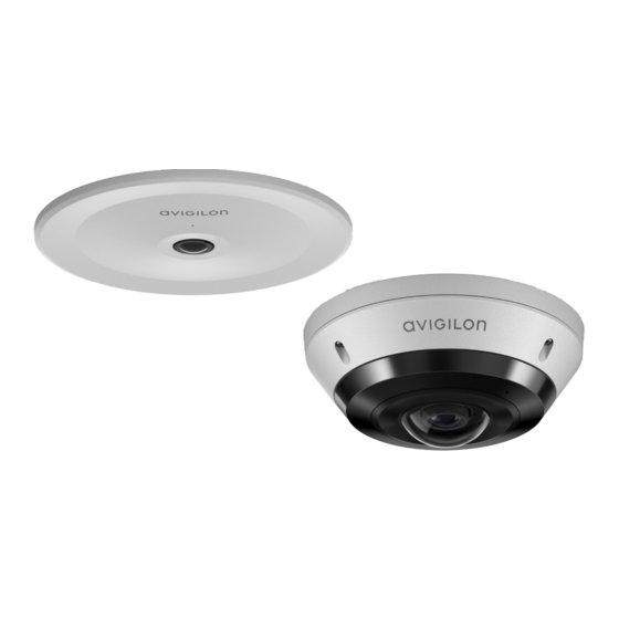
- Page 1 Installation Guide Avigilon™ H5A Fisheye Camera Models: 8.0C-H5A-FE-DO1 12.0W-H5A-FE-DO1 8.0C-H5A-FE-DO1-IR 12.0W-H5A-FE-DO1-IR 8.0C-H5A-FE-DC1 12.0W-H5A-FE-DC1...
- Page 2 Important Safety Information This manual provides installation and operation information and precautions for the use of this device. Incorrect installation could cause an unexpected fault. Before installing this equipment read this manual carefully. Please provide this manual to the owner of the equipment for future reference. This Warning symbol indicates the presence of dangerous voltage within and outside the product enclosure that may result in a risk of electric shock, serious injury or death to persons if proper precautions are not followed.
- Page 3 received, including interference that may cause undesired operation. This Class B digital apparatus complies with Canadian ICES-003. This equipment has been tested and found to comply with the limits for a Class B digital device, pursuant to Part 15 of the FCC rules. These limits are designed to provide reasonable protection against harmful interference in a residential installation.
- Page 4 Legal Notices © 2021, Avigilon Corporation. All rights reserved. AVIGILON, the AVIGILON logo, AVIGILON CONTROL CENTER, and ACC are trademarks of Avigilon Corporation. ONVIF is a trademark of Onvif, Inc. Other names or logos mentioned herein may be the trademarks of their respective owners. The absence of the symbols ™ and ®...
-
Page 5: Table Of Contents
Table of Contents Overview H5A-FE-DO — Surface Mount Cover View Internal View Bottom View Wall Plate Adapter View H5A-FE-DC — In-Ceiling Mount Cover View Internal View In-Ceiling Mount View H5A-FE-MT-NPTA — Pendant Mount NPT Adapter View Pendant Wall Mount Bracket View Pendant Wall Mount View Preparing the Installation Pre-Deployment In-Box Configuration... - Page 6 Installation Steps Mounting in the Correct Orientation Using the In-Ceiling Mounting Adapter Installing the Camera Base into the Mounting Adapter Connecting Cables Installing the In-Ceiling Cover Pendant Mount Installation Required Tools and Materials Camera Package Contents Installation Steps Mounting the Camera to a Pipe Mounting the Camera to the Pendant Wall Mount Installing the Camera into the NPT Adapter Connecting Cables...
- Page 7 Limited Warranty and Technical Support...
-
Page 8: Overview
Overview H5A-FE-DO — Surface Mount Cover View 1. Dome cover Vandal resistant dome cover. 2. Tamper resistant screws Star-shaped captive screws to fix the dome cover to the base. 3. IR illuminator Provides scene illumination in the IR spectrum for supported camera models. 4. -
Page 9: Internal View
Internal View 1. Ethernet port Accepts an Ethernet connection to a network. Server communication and image data transmission occurs over this connection. Also receives power when it is connected to a network that provides Power over Ethernet. 2. Lanyard Anchors the cover to the camera base. 3. -
Page 10: Bottom View
8. Firmware revert button Resets the camera to its factory default settings. 9. Cable entry hole An entry hole for the cables required for camera operation. 10. I/O connector block Provides connections to external input/output and audio devices. 11. Serial number tag Device information, product serial number and part number label. -
Page 11: Wall Plate Adapter View
Device information, product serial number and part number label. 4. Side conduit tab For installations that require cabling through a side conduit, this tab should be removed and replaced by the conduit shroud. 5. Cable entry hole An entry hole for the cables required for camera operation. Wall Plate Adapter View 1. -
Page 12: H5A-Fe-Dc - In-Ceiling Mount
4" gang box Mounting surface US standard single gang box 4. Orientation post Orientation post that fits properly into the cable entry hole area of the camera base. Post will prevent installation in the incorrect orientation. H5A-FE-DC — In-Ceiling Mount Cover View 1. -
Page 13: Internal View
Internal View 1. Ethernet port Accepts an Ethernet connection to a network. Server communication and image data transmission occurs over this connection. Also receives power when it is connected to a network that provides Power over Ethernet. 2. Lanyard Anchors the cover to the camera base. 3. -
Page 14: In-Ceiling Mount View
Status LED Indicator on page 60. 8. Link LED indicator Amber LED indicates if there is an active connection in the Ethernet port. 9. Firmware revert button Resets the camera to its factory default settings. 10. Cable entry hole An entry hole for the cables required for camera operation. 11. -
Page 15: H5A-Fe-Mt-Npta - Pendant Mount
3. Camera mounting posts Align the mounting posts on the in-ceiling adapter to the mounting slots on the camera base. 4. Orientation post Orientation post that fits properly into the cable entry hole area of the camera base. Post will prevent installation in the incorrect orientation. -
Page 16: Pendant Wall Mount Bracket View
An adapter for attaching the pendant NPT mount to an NPT pipe or wall arm. 4. Lock nut Lock nut for securing the pendant NPT mount to an NPT pipe or wall arm. 5. 1-1/2” NPT thread mount Standard female 1-1/2” NPT thread mount for mounting the camera to an NPT pipe or wall arm. 6. -
Page 17: Pendant Wall Mount View
Pendant Wall Mount View 1. 1-1/2” NPS thread mount Female NPS thread mount for pendant camera installations. 2. Pendant wall mount screws Screws for securing the pendant wall mount to the mounting bracket. 3. NPT pipe entry hole A 3/4” NPT threaded hole for NPT pipe conduits. Pendant Wall Mount View... -
Page 18: Preparing The Installation
Preparing the Installation Pre-Deployment In-Box Configuration The camera comes equipped with an RJ45 configuration cable pre-installed for users that want to configure camera settings before installing the camera. The RJ45 connector on the configuration cable is accessible through the small flap on the side of the camera box for easy configuration before unpacking the camera. Note: We recommend that you do not exceed 3 hours of leaving your camera connected during in- box configuration with ambient temperatures between 20 °C –... -
Page 19: Removing The Fisheye Cover
Removing the Fisheye Cover 1. Remove the cover by loosening the screws that fix the cover to the base. Use the provided star- shaped screwdriver to loosen the screws. Note: Be careful not to scratch or touch the dome bubble. The resulting marks or fingerprints may affect the overall image quality. -
Page 20: Mounting And Aiming Video Analytics Cameras
2. Lift the cover off the camera base and set it aside. 3. Unplug and remove the RJ45 in-box configuration cable that comes pre-installed on the camera. Mounting and Aiming Video Analytics Cameras When installing an Avigilon H5A Fisheye video analytics camera, follow the listed mounting and aiming recommendations to maximize the camera's analytics capabilities: The camera should be mounted on a ceiling and look down on the scene. -
Page 21: Inserting An Ethernet Cable Through The Single-Hole Grommet
If the camera is installed outdoors, it is important that the cables be insulated against the weather. Provided with the camera are two rubber grommets for waterproofing the required cables: Use the single-hole rubber grommet for installations using PoE power and require only the Ethernet cable. -
Page 22: Inserting Cables Through The 3-Hole Grommet
Inserting Cables through the 3-Hole Grommet Note: The Ethernet cable must be uncrimped to perform this procedure. The camera includes an I/O terminal for input/output and audio connections, an external power connector, and an Ethernet connector. If you are connecting 2 or more cables to the camera, follow this procedure for using the 3-hole sealing grommet to insulate the cables from the weather. - Page 23 3. If you are using other cables, pull one or both of the tabs on the grommet to open the secondary holes for the additional cables. 4. Thread the additional cables through the secondary grommet holes. Threading thin cables through the secondary holes may require the use of silicone sealant at the opening to ensure weather proofing.
-
Page 24: Surface Mount Installation
Surface Mount Installation Required Tools and Materials The following tools are required to complete the installation but are not included in the package: Appropriate tool for cutting the cable access hole Small slotted screwdriver with 5/64” or 2 mm blade width — for connecting power when not using Power over Ethernet No. - Page 25 Tip: Before removing the mounting template after cutting or drilling the required holes, mark or otherwise make note of the direction the orientation arrow is facing. This will help you to align the camera body in the same orientation when installing. When installing the camera to a wall, make sure that the orientation arrow is facing up, as shown in the diagram below.
-
Page 26: Mounting The Camera To A Ceiling Or Wall
Mounting the Camera to a Ceiling or Wall Perform the following steps if the required cables will be coming from inside the mounting surface and the camera will be mounted immediately over the cable hole. Use this procedure on surfaces that can be easily drilled into, and when the cables should be kept out of sight. - Page 27 5. Align the up orientation arrow on the camera base with the arrow on the mounting template. Align the mounting slots on the camera base to the drilled pilot holes and use the provided self-tapping screws to secure the camera to the mounting surface. 6.
-
Page 28: Mounting The Camera Using The Side Conduit Entry Hole
7. Push the rubber sealing grommet with the required cables into the cable entry hole on the camera base. The thread around the grommet should line up with the cable entry hole. The rubber grommet should be pressed firmly into the cable entry hole to create a seal. Mounting the Camera Using the Side Conduit Entry Hole Perform the following steps if the required cables will be run along the mounting surface. - Page 29 2. Align the conduit for the cables so that the end of the conduit falls inside the conduit landing area of the mounting template. 3. Hammer the supplied plastic anchors into the holes. 4. Arrange and feed the required cables through the conduit. 5.
- Page 30 6. Use the same screw to install the optional conduit shroud to the cable entry tab position. The conduit shroud is compatible with up to 1/2" conduits. 7. Pull the required cables through the cable entry hole on the camera base. Mounting the Camera Using the Side Conduit Entry Hole...
- Page 31 8. Align the up orientation arrow on the camera base with the arrow on the mounting template. Align the mounting slots on the camera base to the drilled pilot holes and use the provided self-tapping screws to secure the camera to the mounting surface. Tip: Make sure the cables run through the space provided by the conduit shroud and that they are not pinched.
-
Page 32: Mounting The Camera To An Electrical Box
10. Push the rubber sealing grommet with the required cables into the cable entry hole on the camera base. The thread around the grommet should line up with the cable entry hole. The rubber grommet should be pressed firmly into the cable entry hole to create a seal. Mounting the Camera to an Electrical Box Perform the following steps if the required electrical components and cables must be contained in an electrical gang box. - Page 33 page 17. 3. Use the provided machine screws to secure the wall plate adapter to the electrical gang box. 4. Pull the required cables through the electrcal box and a cable entry hole on the wall plate. Then feed the cables through the cable entry hole on the camera base. Mounting the Camera to an Electrical Box...
- Page 34 5. Align the up orientation arrow on the camera base with the arrow on the wall plate adapter. Align the mounting slots on the camera base to the mounting posts on the wall plate adapter and push the camera base onto the adapter. Mounting the Camera to an Electrical Box...
- Page 35 6. Twist the camera base clockwise until the posts come to the right end of the mounting slots. 7. Tighten the mounting posts to fix the camera base into place. 8. Pull the required cables through the rubber sealing grommet. For more information, see Preparing the Cables on page 13.
-
Page 36: Connecting Cables
9. Push the rubber sealing grommet with the required cables into the cable entry hole on the camera base. The thread around the grommet should line up with the cable entry hole. The rubber grommet should be pressed firmly into the cable entry hole to create a seal. Connecting Cables Refer to the diagrams in the Overview section... -
Page 37: Installing The Fisheye Cover
1. Connect a network cable to the camera's Ethernet port (RJ45 connector). 2. If the camera is connected to any external devices, connect the I/O or audio cables to the I/O connector block. For more information, see Connecting to External Audio and I/O Devices on page 58. - Page 38 1. Attach the lanyard to the cover. 2. Attach the cover to the base and tighten the screws with the star-shaped screwdriver. 3. Remove the plastic cover on the dome bubble. Installing the Fisheye Cover...
-
Page 39: In-Ceiling Mount Installation
In-Ceiling Mount Installation Required Tools and Materials The following tools are required to complete the installation but are not included in the package: Appropriate tool for cutting the entry hole in the mounting surface Small slotted screwdriver with 5/64” or 2 mm blade width — for connecting power when not using Power over Ethernet Camera Package Contents Ensure the in-ceiling mounted camera package contains the following:... - Page 40 diagram below. Mounting in the Correct Orientation...
-
Page 41: Using The In-Ceiling Mounting Adapter
Using the In-Ceiling Mounting Adapter If the camera needs to be installed into a ceiling, install the in-ceiling mounting adapter into the ceiling first. Note: The maximum supported ceiling thickness is 32 mm (1.25"). 1. Use the in-ceiling mounting template to cut an entry hole for the camera into the ceiling. Mark or otherwise make note of the position of the orientation arrow so that the other parts can be mounted in the same orientation. - Page 42 2. Insert the in-ceiling mounting adapter into the entry hole then pull the required cables through the adapter. Ensure the orientation arrow on the adapter is facing the same direction as it did on the mounting template. 3. Pull off the elastic clamp retainer holding the clamps in place. Using the In-Ceiling Mounting Adapter...
- Page 43 4. Push the orange clamp handles up so that the metal arms extend outside the mounting adapter. 5. With your thumb on the outside edge of the mounting adapter and your forefinger on one of the orange clamp handles, pinch the clamp down until the clamp is secured. Using the In-Ceiling Mounting Adapter...
-
Page 44: Installing The Camera Base Into The Mounting Adapter
6. Repeat the previous step on the other side. Make sure both clamps are level and horizontal. Installing the Camera Base into the Mounting Adapter After you install the mounting adapter, mount the camera base to the adapter. 1. Attach the lanyard on the mounting adapter to the anchor on the camera base. 2. - Page 45 mounting slots on the camera base to the mounting posts on the in-ceiling adapter and push the camera base onto the adapter. 4. Twist the camera base clockwise until the posts come to the right end of the mounting slots and the alignment feature is in the locked position.
- Page 46 5. Tighten the mounting posts to fix the camera base into place. Ensure that the orientation arrows on the in-ceiling adapter and camera base point in the same direction. 6. Pull the required cables through the rubber sealing grommet. For more information, see Preparing the Cables on page 13.
-
Page 47: Connecting Cables
7. Install the grommet into the cable entry hole on the camera base. Make sure the grommet flange is securely seated on the inside and outside of the cable entry hole. 8. Use the cable clip to hold the Ethernet cable in the correct position. Connecting Cables Refer to the diagrams in the Overview section... -
Page 48: Installing The In-Ceiling Cover
1. Connect a network cable to the camera's Ethernet port (RJ45 connector). 2. If the camera is connected to any external devices, connect the I/O or audio cables to the I/O connector block. For more information, see Connecting to External Audio and I/O Devices on page 58. - Page 49 1. Attach the lanyard to the in-ceiling cover. 2. Push the in-ceiling cover onto the camera base. 3. Rotate the cover clockwise while pushing up so that it clicks into place. Installing the In-Ceiling Cover...
-
Page 50: Pendant Mount Installation
Pendant Mount Installation Required Tools and Materials The following tools are required to complete the installation but are not included in the package: Appropriate tool for cutting the cable access hole, if required Small slotted screwdriver with 5/64” or 2 mm blade width — for connecting power when not using Power over Ethernet If you will be installing the NPT adapter (H5A-FE-MT-NPTA1), you will need: 1-1/2"... - Page 51 MT-NPTA1). Note: This procedure requires a 1-1/2” NPT-female to NPT-female pipe adapter and conduit pipe that are not supplied by Avigilon and should be sourced separately. It is recommended that the NPT adapter be mounted to a 1-1/2” conduit pipe. 1.
-
Page 52: Mounting The Camera To The Pendant Wall Mount
5. Carefully tighten the lock nut until the NPT adapter is secured to the conduit pipe. Mounting the Camera to the Pendant Wall Mount If the camera will be using the pendant wall mount, you will need to install the NPT adapter as well. 1. - Page 53 3. Fasten the pendant wall mount bracket to the mounting surface. 4. Insert the pendant wall mount over the bracket mounting tabs. 5. Pull the required cables through the preferred cable entry hole on the pendant wall mount. If you are using the pipe entry hole, pull the cables through the pipe conduit then the wall mount.
- Page 54 6. Tighten the wall mount screws to secure the wall mount to the bracket. Use the T20 star-shaped key provided in the camera package. 7. Loosely thread the lock nut onto the NPT adapter, then secure the NPT adapter into the pendant wall mount.
-
Page 55: Installing The Camera Into The Npt Adapter
8. Carefully tighten the lock nut until the NPT adapter is secured to the wall mount. Installing the Camera into the NPT Adapter Before installing the camera, you must first prepare either the wall mount or NPT pipe mount. Note: The following steps show installation of the camera into NPT adapter installed onto a pipe. The steps are the same for installing the camera to the wall mount. - Page 56 1. Attach the lanyard to the camera base. Pull the required cables through the cable entry hole. 2. Align the mounting slots on the camera base to the mounting posts on the NPT adapter and push the camera base onto the adapter. 3.
- Page 57 4. Tighten the mounting posts to fix the camera base into place. 5. Pull the required cables through the rubber sealing grommet. For more information, see Preparing the Cables on page 13. Installing the Camera into the NPT Adapter...
-
Page 58: Connecting Cables
6. Push the rubber sealing grommet with the required cables into the cable entry hole on the camera base. The thread around the grommet should line up with the cable entry hole. The rubber grommet should be pressed firmly into the cable entry hole to create a seal. Connecting Cables Refer to the diagrams in the Overview section... -
Page 59: Installing The Fisheye Cover
1. Connect a network cable to the camera's Ethernet port (RJ45 connector). 2. If the camera is connected to any external devices, connect the I/O or audio cables to the I/O connector block. For more information, see Connecting to External Audio and I/O Devices on page 58. - Page 60 1. Attach the lanyard to the cover. 2. Attach the cover to the base and tighten the screws with the star-shaped screwdriver. 3. Remove the plastic cover on the dome bubble. Installing the Fisheye Cover...
-
Page 61: Connecting To The Camera
Connecting to the Camera Initializing a Camera Username and Password Important: You must create a user with administrator privileges before the camera is operational. The first user can be created using any of the following methods: Camera's Web Interface: enter the camera's IP address in a web browser to access the web interface. -
Page 62: Accessing The Live Video Stream
Device's web browser interface: http://<camera IP address>/. Network Video Management software application (for example, the Avigilon Control Center™ software). ARP/Ping method. For more information, see Setting the IP Address Using the ARP/Ping Method on page 63. Accessing the Live Video Stream Live video stream can be viewed using one of the following methods: Web browser interface: http://<... -
Page 63: Configuring The Microphone
1. Locate the microphone switch on the camera assembly. 2. Slide the switch from the default OFF position to ON to enable the microphone. Configuring the Microphone The H5A Fisheye Camera features two microphones: a built-in microphone and an external audio input. After you've connected the required microphones, you can configure the microphones or line level audio input from the camera web interface or in the ACC Client software. -
Page 64: Configuring The Camera
Configuring the Camera Once installed, use one of the following methods to configure the camera: If you have installed multiple cameras, you can use the Avigilon Camera Configuration Tool to configure common settings. For more information, see the Avigilon Camera Configuration Tool User Guide. -
Page 65: Cable Connections
Cable Connections Connecting External Power If PoE is not available, the camera needs to be powered through the removable power connector block. Refer to the Overview section for the location of the power connector block. To connect power to the power connector block, complete the following steps: 1. - Page 66 1. Digital Output — When active, Output is internally connected with the Ground pin. Circuit is open when inactive. Maximum load is 25 VDC, 120 mA. 2. Ground 3. Digital Input — To activate, connect the Input to the Ground pin. To deactivate, leave disconnected or apply between 3-15 V.
-
Page 67: Connection Status Led Indicator
Connection Status LED Indicator Once connected to the network, the green Connection Status LED indicator will display the progress in connecting to the Network Video Management software. The following table describes what the LED indicator shows: Connection State Connection Status Description LED Indicator Obtaining... - Page 68 LED Behavior Suggested Solution Both LEDs are blinking several Perform a factory reset of the camera using the physical times at the same time, then firmware revert button. Resetting through the camera's web pause and repeat the blinking interface will not produce the desired result. A different LED blinking pattern Perform a factory reset of the camera using the physical than those described above...
-
Page 69: Resetting To Factory Default Settings
Resetting to Factory Default Settings If the device no longer functions as expected, you can choose to reset the device to its factory default settings. Use the firmware revert button to reset the device. The firmware revert button is shown in the following diagram: 1. -
Page 70: Setting The Ip Address Using The Arp/Ping Method
Setting the IP Address Using the ARP/Ping Method Complete the following steps to configure the camera to use a specific IP address: Note: The ARP/Ping Method will not work if the Disable setting static IP address through ARP/Ping method checkbox is selected in the camera's web browser interface. For more information, see the Avigilon High Definition H4 and H5 IP Camera Web Interface User Guide. -
Page 71: Cleaning
Cleaning Dome Bubble If the video image becomes blurry or smudged in areas, it may be because the dome bubble requires cleaning. Note: Cleaning the dome bubble does not apply to in-ceiling models as they do not have a dome bubble. - Page 72 Limited Warranty and Technical Support Avigilon warranty terms for this product are provided at avigilon.com/warranty. Warranty service and technical support can be obtained by contacting Avigilon Technical Support: avigilon.com/contact. Limited Warranty and Technical Support...
Need help?
Do you have a question about the Avigilon 8.0C-H5A-FE-DO1 and is the answer not in the manual?
Questions and answers