
Subscribe to Our Youtube Channel
Related Manuals for Motorola solutions L5Q


Summary of Contents for Motorola solutions L5Q
- Page 1 L5Q Installation Guide APRIL 2021 *MN007598A01* MN007598A01-AD © 2021 Motorola Solutions, Inc. All rights reserved...
- Page 2 Motorola Solutions, Inc. Furthermore, the purchase of Motorola Solutions products shall not be deemed to grant either directly or by implication, estoppel or otherwise, any license under the copyrights, patents or patent applications of Motorola Solutions, except for the normal non-exclusive, royalty-free license to use that arises by operation of law in the sale of a product.
- Page 3 Email: vigilantsupport@motorolasolutions.com Document History Version Description Date MN007598A01-AA Initial Release October 2020 MN007598A01-AB Compliance with the new Motorola Solutions design November 2020 standard. MN007598A01- The following sections are updated: March 2021 • L5Q Overview on page 6 • Getting Started on page 10 •...
- Page 4 MN007598A01-AD Legal and Support Special Notations The following special notations are used throughout the text to highlight certain information or items: Table 1: Special Notations Example Description Menu key or Camera button Bold words indicate a name of a key, button, or soft menu item.
-
Page 5: Table Of Contents
MN007598A01-AD List of Figures List of Figures Figure 1: Attaching Antennas ........................ 10 Figure 2: Slide in the Spreader Bar ....................... 10 Figure 3: Removing Ball Portion ......................11 Figure 4: Inserting Ball Mount Threads ....................11 Figure 5: Securing Ball Portion ......................12 Figure 6: Securing the Ball Joint Mount ....................12 Figure 7: Power Cable Female Connector End ..................13 Figure 8: Exposing the Battery Compartment .................. -
Page 6: L5Q Overview
Chapter 1 : L5Q Overview Chapter 1 L5Q Overview The L5Q License Plate Recognition (LPR) camera is designed to perform license plate collection for low speed (less than 45 MPH) and low volume residential traffic (3500 Average Annual Daily Traffic). L5Q Equipment List... - Page 7 MN007598A01-AD Chapter 1 : L5Q Overview Equipment Photo Security Enclosure Solar Panel Kit Shielded Power Cable...
- Page 8 MN007598A01-AD Chapter 1 : L5Q Overview Equipment Photo Solar Panel Mounting Bracket Security Enclosure Mounting Bracket ™ Master Cable Lock...
- Page 9 MN007598A01-AD Chapter 1 : L5Q Overview Equipment Photo Hose Clamps (four pieces) and 5 mm Hex Key Optional Equipment (Sold Separately) Required for use without Solar Panel or 12VDC input: • AA Lithium Ion Batteries (12 pieces) Required for installing a new pole: •...
-
Page 10: Getting Started
MN007598A01-AD Chapter 2 : Getting Started Chapter 2 Getting Started This section provides instructions to prepare the L5Q camera for use. Attaching the L5Q Antennas Procedure: 1 Screw both antennas onto the faceplate of the camera. Figure 1: Attaching Antennas 2 Slide the Horizontal Spreader Bar into a place down to the stops on the back of the antennas, just above the spreader bar. -
Page 11: Figure 3: Removing Ball Portion
MN007598A01-AD Chapter 2 : Getting Started Installing the Ball Mount Procedure: 1 Loosen the ball lock and remove the ball portion from the security enclosure mounting bracket. Figure 3: Removing Ball Portion 2 Insert the ball mount threads through the rear of the security enclosure. Figure 4: Inserting Ball Mount Threads 3 Secure the ball mount with the second locking nut inside the Security Enclosure. -
Page 12: Figure 5: Securing Ball Portion
MN007598A01-AD Chapter 2 : Getting Started Figure 5: Securing Ball Portion Securing the Ball Joint Mount Procedure: 1 Tighten the outer nut with the 0.5 in. Wrench . 2 Use the 0.5 in. Socket Wrench to hold the inner nut in place. 3 Check the threads of the bolt, to ensure that they do not extend past the edge of the nut on the inside of the Security Enclosure, as shown in the following image. -
Page 13: Figure 7: Power Cable Female Connector End
MN007598A01-AD Chapter 2 : Getting Started Installing the Power Cable Procedure: 1 Remove the shielded power cable from solar panel housing. 2 Slide the female connector end of the shielded power cable through the bottom left hole of the security enclosure. Figure 7: Power Cable Female Connector End Connecting the Solar Panel Battery Lead Procedure:... -
Page 14: Setting The Camera Date And Time From Reconyx Connect
MN007598A01-AD Chapter 2 : Getting Started Figure 9: Connecting the Battery Terminal 4 Replace and tighten the bolt on the rear of the solar panel. Setting the Camera Date and Time NOTICE: For firmware version 0224a and application version 1.1.0, the camera date and time can also be set remotely from the Reconyx Connect application. -
Page 15: Figure 10: Setting The Camera Date And Time From Reconyx Connect
MN007598A01-AD Chapter 2 : Getting Started Procedure: 1 Open the Reconyx Connect application. 2 Tap Cameras. 3 Select the camera that needs its date or time changed. 4 Tap More→Camera Date/Time. Figure 10: Setting the Camera Date and Time from Reconyx Connect 5 To adjust the hour, tap Up and Down arrows. - Page 16 Chapter 3 Hardware Installation This section provides the instructions to mount the L5Q Camera and Solar Panel. The ideal mounting location for the camera and Solar Panel is on a pole closest to the lane of traffic being captured that also offers the Solar Panel a southern-facing unobstructed view of the sun. The recommended mounting height of the camera and solar panel is at least 8 ft to place the installation out of reach from street level.
-
Page 17: Figure 11: Mounting The Solar Panel To A Pole
MN007598A01-AD Chapter 3 : Hardware Installation Option Actions Figure 11: Mounting the Solar Panel to a Pole Mounting the solar panel a Mount the solar panel mounting bracket to the wooden to a flat wooden surface. surface using the Lag Bolts and Impact Wrench or a Sock- et Wrench. -
Page 18: Figure 13: Mounting The Security Enclosure To A Pole
MN007598A01-AD Chapter 3 : Hardware Installation Option Actions e Wrap the excess cable length on the back of the Solar Panel as shown in the following figure. Figure 13: Mounting the Security Enclosure to a Pole Mounting the Security a Mount the Security Enclosure Mounting Bracket to the Enclosure to a Flat wooden surface using the Lag Bolts and Impact Wrench Wooden Surface. -
Page 19: Affixing The Front Faceplate
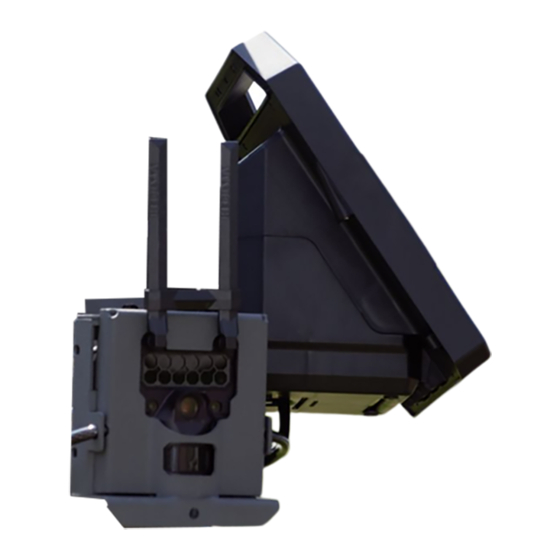
MN007598A01-AD Chapter 3 : Hardware Installation Figure 15: Plug in the Power Cable Affixing the Front Faceplate Procedure: 1 Affix the front faceplate of the Security Enclosure to the camera by sliding it over the antennas. Figure 16: Affixing the Front Faceplate 2 Secure any excess power cable with a zip tie. -
Page 20: Figure 17: Locking The Cable Lock
MN007598A01-AD Chapter 3 : Hardware Installation 2 Feed one looped cable end through the other looped cable end. Slide the lock through the latch hole in the bottom of the Security Enclosure and through the free looped cable end. 3 Lock the Master Cable Lock and remove the key. Figure 17: Locking the Cable Lock... - Page 21 Camera Adjustment Chapter 4 Camera Adjustment This section provides the instructions to adjust the L5Q Camera after the camera is mounted. Measuring the Camera Height Procedure: 1 Use the Tape Measure to measure the height from the camera infrared sensor to the ground.
-
Page 22: Figure 18: Infrared Sensor Aiming Distance
MN007598A01-AD Chapter 4 : Camera Adjustment Figure 18: Infrared Sensor Aiming Distance Testing the Camera with the Application Procedure: 1 Open the Reconyx Connect application. Figure 19: Selecting the Camera 2 At the bottom of the screen, tap Camera. 3 From the list, select the camera that you want to aim. 4 At the bottom right corner of the screen, tap Aim Mode→Show motion zone overlay . -
Page 23: Figure 20: Configuring The Camera Aim Setting
MN007598A01-AD Chapter 4 : Camera Adjustment Figure 20: Configuring the Camera Aim Setting NOTICE: Tapping Aim Mode wakes up the camera and places it into aim mode. Images continue to populate for two minutes at a rate of approximately six seconds between each image. -
Page 24: Figure 22: Aiming To The Center Of The Image Frame
MN007598A01-AD Chapter 4 : Camera Adjustment 3 When the aiming point is established, rotate the camera to level the image as much as possible by using the bottom of the image frame as a guide. 4 Retighten the ball lock to secure the camera in place. NOTICE: The windowing configuration below is used to center the aiming within the image frame. -
Page 25: Figure 23: Shifting The Image
MN007598A01-AD Application Configuration Chapter 5 Application Configuration This section provides the instructions to adjust the image capture by using the Reconyx Connect application. Shifting the Image Prerequisites:Depending on camera placement, the image may need shifting to accommodate proper plate capture. Procedure: 1 At the bottom of the screen, tap Camera. -
Page 26: Figure 24: Selecting The Camera
MN007598A01-AD Chapter 5 : Application Configuration Modifying the Image Capture Timing Prerequisites:Depending on the speed of the vehicle and camera placement, the timing between image captures you may need to shorten the timing to accommodate a proper license plate image capture. -
Page 27: Figure 25: Modifying The Time Between Pictures
MN007598A01-AD Chapter 5 : Application Configuration Figure 25: Modifying the Time between Pictures Motion Events Settings Other settings in the Motion Events menu can be adjusted to optimize image capture. Table 5: Motion Events Settings Descriptions Settings Description Motion Pictures Enables the capturing of multiple images. - Page 28 MN007598A01-AD Chapter 5 : Application Configuration Because the Total Event Time is only 1.8 seconds and is 0.2 seconds less than the recommended 2 seconds, the Quiet Period should be increased. Therefore, the Quiet Period should be increased by at least 0.2 seconds.
Need help?
Do you have a question about the L5Q and is the answer not in the manual?
Questions and answers