
Related Manuals for Texas Instruments TDC1000-GASEVM


Summary of Contents for Texas Instruments TDC1000-GASEVM
- Page 1 TDC1000-GASEVM User’s Guide User's Guide Literature Number: SNIU026A March 2015 – Revised December 2015...
-
Page 2: Table Of Contents
11.3 Firmware Upgrade ..................TDC1000-GASEVM Board Layout ....................TDC1000-GASEVM Schematic ..................TDC1000-BSTEVM Board Layout ......................BSTEVM Schematic .......................... Revision History Table of Contents SNIU026A – March 2015 – Revised December 2015 Submit Documentation Feedback Copyright © 2015, Texas Instruments Incorporated... - Page 3 ......................Board Dimensions ..................TDC1000-GASEVM Schematic 1 ..................TDC1000-GASEVM Schematic 2 ..................TDC1000-GASEVM Schematic 3 ......................BSTEVM Layout ......................TDC1000-BSTEVM SNIU026A – March 2015 – Revised December 2015 List of Figures Submit Documentation Feedback Copyright © 2015, Texas Instruments Incorporated...
- Page 4 List of Tables ........................Jumper List of Tables SNIU026A – March 2015 – Revised December 2015 Submit Documentation Feedback Copyright © 2015, Texas Instruments Incorporated...
-
Page 5: General Overview
1. The TDC1000-GASEVM has been designed for Gas Flow applications. The passive components that determine the first order filter of the Rx signal path have been tuned for frequencies between 58 kHz to 300 KHz. -
Page 6: Setup
200Khz transducer with 10 excitation pulses the duration = (# pulses/Xmit freq)*1e6+30us or 80 us. 10. Run the GUI as explained in SNIA020 Figure 1. TDC1000-GASEVM TDC1000-GASEVM and TDC1000-BSTEVM Kit User’s Guide SNIU026A – March 2015 – Revised December 2015 Submit Documentation Feedback Copyright © 2015, Texas Instruments Incorporated... -
Page 7: Tdc1000-Bstevm Board
Setup www.ti.com Figure 2. TDC1000-BSTEVM Board SNIU026A – March 2015 – Revised December 2015 TDC1000-GASEVM and TDC1000-BSTEVM Kit User’s Guide Submit Documentation Feedback Copyright © 2015, Texas Instruments Incorporated... -
Page 8: Software Installation
3. Follow the pop-up screen instructions. Click “Next” to install the software. Figure 3. TDC1000-7200EVM Installation Directory 4. When the installation is done, click “Finish”. TDC1000-GASEVM and TDC1000-BSTEVM Kit User’s Guide SNIU026A – March 2015 – Revised December 2015 Submit Documentation Feedback... -
Page 9: Tdc1000-Bstevm Setup And Operation
TDC1000-BSTEVM Setup and Operation Connections 1. Connect the USB cable (J2) from the TDC1000-GASEVM to the PC. 2. Plug the TDC1000-BSTEVM (HV board) into the TDC1000-GASEVM (see Figure 3. Attach the transducer wires to the connectors J1 and J2 on the HV board. -
Page 10: Launching The Software
Channel 2. Make sure to uncheck the box "TDC1000-HV Driver EN2" in the GUI and to also place the jumper JP1 on the HV board to "LV" for low voltage. TDC1000-GASEVM and TDC1000-BSTEVM Kit User’s Guide SNIU026A – March 2015 – Revised December 2015 Submit Documentation Feedback Copyright ©... -
Page 11: Setup Tab In Tdc1000-Tdc7200Evm
Launching the Software www.ti.com Figure 5. SETUP Tab in TDC1000-TDC7200EVM SNIU026A – March 2015 – Revised December 2015 TDC1000-GASEVM and TDC1000-BSTEVM Kit User’s Guide Submit Documentation Feedback Copyright © 2015, Texas Instruments Incorporated... - Page 12 Voltage Across Connector J1, EN1 Signal on Oscilloscope 6. Observe the following signals: TDC1000's START (dark blue) on the TDC1000-GASEVM, VDD of driver IC U2(light blue) on the HV board, transmit pulses on transducer connector J1 (green) and EN1 (pink) signals on the oscilloscope as shown in Figure 6.
- Page 13 TDC1000's START Pulse (Dark Blue), TDC1000's Tx Signal (Light Blue), and the Boosted 30 V of TD1000's Tx Signal (Green) SNIU026A – March 2015 – Revised December 2015 TDC1000-GASEVM and TDC1000-BSTEVM Kit User’s Guide Submit Documentation Feedback Copyright © 2015, Texas Instruments Incorporated...
-
Page 14: Clock Selection
Steps to Select the CPU Clock 1. On the TDC1000-GASEVM, place the JP6 Jumper on the CPU position Figure 8. Place Jumper on JP6 to Use the CPU Clock TDC1000-GASEVM and TDC1000-BSTEVM Kit User’s Guide SNIU026A –... -
Page 15: Select Cpu-Clk
2. Select CPU_CLK on the SETUP tap of the GUI. A message will pop up. Click "OK". Figure 9. Select CPU-CLK SNIU026A – March 2015 – Revised December 2015 TDC1000-GASEVM and TDC1000-BSTEVM Kit User’s Guide Submit Documentation Feedback Copyright © 2015, Texas Instruments Incorporated... -
Page 16: Clock Options
4. Figure 11 shows possible excitation pulses using the CPU clock or on-board oscillator of 8MHz. TDC1000-GASEVM and TDC1000-BSTEVM Kit User’s Guide SNIU026A – March 2015 – Revised December 2015 Submit Documentation Feedback Copyright © 2015, Texas Instruments Incorporated... -
Page 17: Possible Excitation Pulses
28,847 14,423 7,212 2,000,000 1,000,000 500,000 250,000 125,000 62,500 31,250 15,625 7,813 Figure 11. Excitation Pulses Chart SNIU026A – March 2015 – Revised December 2015 TDC1000-GASEVM and TDC1000-BSTEVM Kit User’s Guide Submit Documentation Feedback Copyright © 2015, Texas Instruments Incorporated... -
Page 18: Troubleshooting
When placing the jumper in LV position (on pins 1 and 2), “TDC1000-HV Driver EN2” should be unchecked in the GUI. Otherwise the UCC27531 will pull its output to ground. TDC1000-GASEVM and TDC1000-BSTEVM Kit User’s Guide SNIU026A – March 2015 – Revised December 2015 Submit Documentation Feedback Copyright ©... -
Page 19: 11.3 Firmware Upgrade
3. The MSP430 USB Firmware Upgrade windows will pop up. Click “Next” to proceed on the first prompt. Read and accept the license agreement and click “Next” to continue. SNIU026A – March 2015 – Revised December 2015 TDC1000-GASEVM and TDC1000-BSTEVM Kit User’s Guide Submit Documentation Feedback Copyright © 2015, Texas Instruments Incorporated... -
Page 20: Usb Firmware Upgrade Window
2. Select the Select Firmware button and browse to the firmware file. 3. Click on the Upgrade Firmware button to program the EVM. Close the application when done and restart the TDC1000_7200EVM GUI. TDC1000-GASEVM and TDC1000-BSTEVM Kit User’s Guide SNIU026A – March 2015 – Revised December 2015 Submit Documentation Feedback... -
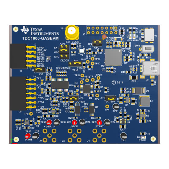
Page 21: Tdc1000-Gasevm Board Layout
TDC1000-GASEVM Board Layout www.ti.com TDC1000-GASEVM Board Layout Figure 15. Top Overlay SNIU026A – March 2015 – Revised December 2015 TDC1000-GASEVM and TDC1000-BSTEVM Kit User’s Guide Submit Documentation Feedback Copyright © 2015, Texas Instruments Incorporated... -
Page 22: Top Solder Mask
TDC1000-GASEVM Board Layout www.ti.com Figure 16. Top Solder Mask TDC1000-GASEVM and TDC1000-BSTEVM Kit User’s Guide SNIU026A – March 2015 – Revised December 2015 Submit Documentation Feedback Copyright © 2015, Texas Instruments Incorporated... -
Page 23: Top Layer
TDC1000-GASEVM Board Layout www.ti.com Figure 17. Top Layer SNIU026A – March 2015 – Revised December 2015 TDC1000-GASEVM and TDC1000-BSTEVM Kit User’s Guide Submit Documentation Feedback Copyright © 2015, Texas Instruments Incorporated... -
Page 24: Mid Layer
TDC1000-GASEVM Board Layout www.ti.com Figure 18. Mid Layer 1 TDC1000-GASEVM and TDC1000-BSTEVM Kit User’s Guide SNIU026A – March 2015 – Revised December 2015 Submit Documentation Feedback Copyright © 2015, Texas Instruments Incorporated... -
Page 25: Mid Layer
TDC1000-GASEVM Board Layout www.ti.com Figure 19. Mid Layer 2 SNIU026A – March 2015 – Revised December 2015 TDC1000-GASEVM and TDC1000-BSTEVM Kit User’s Guide Submit Documentation Feedback Copyright © 2015, Texas Instruments Incorporated... -
Page 26: Bottom Layer
TDC1000-GASEVM Board Layout www.ti.com Figure 20. Bottom Layer TDC1000-GASEVM and TDC1000-BSTEVM Kit User’s Guide SNIU026A – March 2015 – Revised December 2015 Submit Documentation Feedback Copyright © 2015, Texas Instruments Incorporated... -
Page 27: Bottom Solder Mask
TDC1000-GASEVM Board Layout www.ti.com Figure 21. Bottom Solder Mask SNIU026A – March 2015 – Revised December 2015 TDC1000-GASEVM and TDC1000-BSTEVM Kit User’s Guide Submit Documentation Feedback Copyright © 2015, Texas Instruments Incorporated... -
Page 28: Board Dimensions
TDC1000-GASEVM Board Layout www.ti.com Figure 22. Board Dimensions TDC1000-GASEVM and TDC1000-BSTEVM Kit User’s Guide SNIU026A – March 2015 – Revised December 2015 Submit Documentation Feedback Copyright © 2015, Texas Instruments Incorporated... -
Page 29: Tdc1000-Gasevm Schematic
EXT_OSC 142-0701-201 Component value = DNP means do not populate 51.1 OSC_SOURCE_SEL Figure 23. TDC1000-GASEVM Schematic 1 SNIU026A – March 2015 – Revised December 2015 TDC1000-GASEVM and TDC1000-BSTEVM Kit User’s Guide Submit Documentation Feedback Copyright © 2015, Texas Instruments Incorporated... -
Page 30: Tdc1000-Gasevm Schematic
ENABLE MSP_TDC7200_EN CPU_CLK TDC7200PW Component value = DNP means do not populate Figure 24. TDC1000-GASEVM Schematic 2 TDC1000-GASEVM and TDC1000-BSTEVM Kit User’s Guide SNIU026A – March 2015 – Revised December 2015 Submit Documentation Feedback Copyright © 2015, Texas Instruments Incorporated... -
Page 31: Tdc1000-Gasevm Schematic
22µF 1µF 7.5V 0.01µF Component value = DNP means do not populate Figure 25. TDC1000-GASEVM Schematic 3 SNIU026A – March 2015 – Revised December 2015 TDC1000-GASEVM and TDC1000-BSTEVM Kit User’s Guide Submit Documentation Feedback Copyright © 2015, Texas Instruments Incorporated... -
Page 32: Tdc1000-Bstevm Board Layout
TDC1000-BSTEVM Board Layout www.ti.com TDC1000-BSTEVM Board Layout Figure 26. BSTEVM Layout TDC1000-GASEVM and TDC1000-BSTEVM Kit User’s Guide SNIU026A – March 2015 – Revised December 2015 Submit Documentation Feedback Copyright © 2015, Texas Instruments Incorporated... -
Page 33: Bstevm Schematic
BSS84-7-F GPIO2 USB_5V EN_Boost 51.1k 51.1k 100pF 100pF Vdd1_EN 2N7002-7-F 100k Vdd2_EN 2N7002-7-F 100k Figure 27. TDC1000-BSTEVM SNIU026A – March 2015 – Revised December 2015 TDC1000-GASEVM and TDC1000-BSTEVM Kit User’s Guide Submit Documentation Feedback Copyright © 2015, Texas Instruments Incorporated... -
Page 34: Revision History
Changed SETUP Tab ........................• Changed Schematic NOTE: Page numbers for previous revisions may differ from page numbers in the current version. Revision History SNIU026A – March 2015 – Revised December 2015 Submit Documentation Feedback Copyright © 2015, Texas Instruments Incorporated... - Page 35 STANDARD TERMS AND CONDITIONS FOR EVALUATION MODULES Delivery: TI delivers TI evaluation boards, kits, or modules, including any accompanying demonstration software, components, or documentation (collectively, an “EVM” or “EVMs”) to the User (“User”) in accordance with the terms and conditions set forth herein. Acceptance of the EVM is expressly subject to the following terms and conditions.
- Page 36 FCC Interference Statement for Class B EVM devices NOTE: This equipment has been tested and found to comply with the limits for a Class B digital device, pursuant to part 15 of the FCC Rules. These limits are designed to provide reasonable protection against harmful interference in a residential installation.
- Page 37 【無線電波を送信する製品の開発キットをお使いになる際の注意事項】 開発キットの中には技術基準適合証明を受けて いないものがあります。 技術適合証明を受けていないもののご使用に際しては、電波法遵守のため、以下のいずれかの 措置を取っていただく必要がありますのでご注意ください。 1. 電波法施行規則第6条第1項第1号に基づく平成18年3月28日総務省告示第173号で定められた電波暗室等の試験設備でご使用 いただく。 2. 実験局の免許を取得後ご使用いただく。 3. 技術基準適合証明を取得後ご使用いただく。 なお、本製品は、上記の「ご使用にあたっての注意」を譲渡先、移転先に通知しない限り、譲渡、移転できないものとします。 上記を遵守頂けない場合は、電波法の罰則が適用される可能性があることをご留意ください。 日本テキサス・イ ンスツルメンツ株式会社 東京都新宿区西新宿6丁目24番1号 西新宿三井ビル 3.3.3 Notice for EVMs for Power Line Communication: Please see http://www.tij.co.jp/lsds/ti_ja/general/eStore/notice_02.page 電力線搬送波通信についての開発キットをお使いになる際の注意事項については、次のところをご覧くださ い。http://www.tij.co.jp/lsds/ti_ja/general/eStore/notice_02.page SPACER EVM Use Restrictions and Warnings: 4.1 EVMS ARE NOT FOR USE IN FUNCTIONAL SAFETY AND/OR SAFETY CRITICAL EVALUATIONS, INCLUDING BUT NOT LIMITED TO EVALUATIONS OF LIFE SUPPORT APPLICATIONS.
- Page 38 Notwithstanding the foregoing, any judgment may be enforced in any United States or foreign court, and TI may seek injunctive relief in any United States or foreign court. Mailing Address: Texas Instruments, Post Office Box 655303, Dallas, Texas 75265 Copyright © 2015, Texas Instruments Incorporated...
- Page 39 IMPORTANT NOTICE Texas Instruments Incorporated and its subsidiaries (TI) reserve the right to make corrections, enhancements, improvements and other changes to its semiconductor products and services per JESD46, latest issue, and to discontinue any product or service per JESD48, latest issue.
- Page 40 Компания «ЭлектроПласт» предлагает заключение долгосрочных отношений при поставках импортных электронных компонентов на взаимовыгодных условиях! Наши преимущества: Оперативные поставки широкого спектра электронных компонентов отечественного и импортного производства напрямую от производителей и с крупнейших мировых складов; Поставка более 17-ти миллионов наименований электронных компонентов; ...
Need help?
Do you have a question about the TDC1000-GASEVM and is the answer not in the manual?
Questions and answers