Table of Contents
Advertisement
Quick Links
Design Guide: TIDA-050038
Integrated Power Supply Reference Design for NXP i.MX
8M Mini Processor
Description
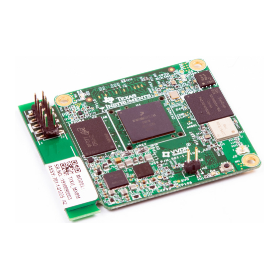
TIDA-050038 is a system-on-module (SoM)
development board integrating two TI PMICs,
TPS6521825 and LP873347, with the NXP™ i.MX 8M
Mini Application Processor. The hardware design also
includes LPDDR4 SDRAM (2GB, x32-bit), QSPI NOR-
Flash (32MB), 16GB eMMC 5.1, 32-kHz RTC
oscillator, WiFi + Bluetooth module, and 9-channel
current monitoring. The SoM board is compatible with
the 8MMiniLPD4-EVK base board for full system
evaluation. This design is intended for any project that
is using the i.MX 8M Mini or i.MX 8M Nano processor
and requires evaluation of alternate power solutions.
Resources
TIDA-050038
Design Folder
TPS6521825
Product Folder
LP873347
Product Folder
INA3221
Product Folder
Search Our E2E™ support forums
LP873347
2.8 V to 5.5 V
0.85 / 0.9 / 0.95 V
BUCK0 (3A)
0.85 / 0.95 / 1.0 V
BUCK1 (3A)
3.3V (DCDC3)
1.2 V
LDO0 (300mA)
0.9 V
LDO1 (300mA)
TPS6521825
0.85 V
DCDC1 (1.8A)
IN_BIAS
4
IN_DCDCx
1.1 V
DCDC2 (1.8A)
3.3 V
DCDC3 (1.8A)
1.8V
DCDC4 (1.6A)
1.8 V
IN_LDO
LDO1 (400mA)
Regulators
IN_BU
0.8 V
DCDC5 (25mA)
1.8 V
CC
DCDC6 (25mA)
Backup (BU) Domain
5 V
IN_LS2
LS2
IN_LS3
LS3
Load Switches 1-3
NOTE: DCDC5/6 are high-efficiency bucks for RTC
An IMPORTANT NOTICE at the end of this TI reference design addresses authorized use, intellectual property matters and other
important disclaimers and information.
TIDUEV8A – December 2019 – Revised February 2020
Submit Documentation Feedback
i.MX 8M Mini, Nano
VDD_VPU, VDD_DRAM, VDD_GPU,
VDD_DRAM_PLL_0P8
VDD_ARM
VDD_MIPI_1P2
VDD_MIPI_0P9
VDD_SOC, VDD_ANA_0P8, VDD_ARM_PLL_0P8,
VDD_USB_0P8, VDD_PCI_0P8
NVCC_DRAM
NVCC_xxx (3.3 V)
NVCC_xxx (1.8 V)
NVDD_ANAx_1P8, VDD_24M_XTAL_1P8,
VDD_DRAM_PLL_1P8, VDD_ARM_PLL_1P8,
VDD_USB_1P8, VDD_PCI_1P8,
VDD_MIPI_1P8
VDD_SNVS_0P8
NVCC_SNVS_1P8
*VDD_VPU not included in Nano
MIPI CSI/DSI
connectors
Integrated Power Supply Reference Design for NXP i.MX 8M Mini Processor
Copyright © 2019–2020, Texas Instruments Incorporated
Features
•
SoM for rapid development of NXP i.MX8M Mini
systems
•
Low-power modes and DVFS supported
•
9-channel current monitoring for DC-DCs and
LDOs
•
Wi-Fi
+ Bluetooth
wireless connectivity
®
®
•
Display connector (DSI), Camera connector (CSI),
additional peripherals on compatible base-board
•
Selectable boot options (SD, eMMC, QSPI)
Applications
•
ARM-based SoM/CoM
•
Intrusion control panel
•
Barcode scanner
•
HVAC gateway
•
Thermostat
•
Building security gateway
•
Panel PLC (HMI)
i
i
Order from RadiumBoards.
1
Advertisement
Table of Contents

Subscribe to Our Youtube Channel
Related Manuals for Texas Instruments TIDA-050038


Summary of Contents for Texas Instruments TIDA-050038
- Page 1 8M Mini Processor Description Features • SoM for rapid development of NXP i.MX8M Mini TIDA-050038 is a system-on-module (SoM) systems development board integrating two TI PMICs, TPS6521825 and LP873347, with the NXP™ i.MX 8M • Low-power modes and DVFS supported Mini Application Processor.
-
Page 2: System Description
System Description TIDA-050038 is first-and-foremost a reference design for powering the NXP i.MX 8M Mini processor from the TPS6521825 and LP873347 PMICs. In order to show that the PMICs can power the processor, it made the most sense to build a SoM board that is compatible with the existing base-board (8MMiniLPD4- EVK), which includes a variety of peripheral connections to assist with development of various end equipments. -
Page 3: System Overview
System Overview www.ti.com System Overview Block Diagram Figure 1. TIDA-050038 Block Diagram SISO MIPI CSI MIPI DSI Micro-SD USB OTG TYPE-C MINI SAS MINI SAS Card SLot JTAG WiFi + Bluetooth LBEE5HY1MW ESD Protection ESD9L5.0ST5G MIPI CSI MIPI DSI SDIO 2 x USB2.0... -
Page 4: Design Considerations
PART NUMBER IC, LPDDR4 SDRAM, 2GB, x32bit, Micron MT53D512M32D2DS-053 WT:D 1866MHz, WFBGA-200 Integrated Power Supply Reference Design for NXP i.MX 8M Mini Processor TIDUEV8A – December 2019 – Revised February 2020 Submit Documentation Feedback Copyright © 2019–2020, Texas Instruments Incorporated... - Page 5 HS400 which is High Speed Mode supporting 400MBps @ 200MHz Dual Data Rate Bus. TIDUEV8A – December 2019 – Revised February 2020 Integrated Power Supply Reference Design for NXP i.MX 8M Mini Processor Submit Documentation Feedback Copyright © 2019–2020, Texas Instruments Incorporated...
- Page 6 In this design, there is an SD card connector on the base-board but the power supply for the SD card is on the TIDA-050038 SoM board. The power supply to the SD Card is selectable between 1.8 V and 3.3 V using a power multiplexer (mux), and both input voltages to the mux are provided by the TPS6521825 PMIC.
- Page 7 MIPI DSI connector • MIPI CSI connector • mini-PCI Express connector • JTAG header TIDUEV8A – December 2019 – Revised February 2020 Integrated Power Supply Reference Design for NXP i.MX 8M Mini Processor Submit Documentation Feedback Copyright © 2019–2020, Texas Instruments Incorporated...
- Page 8 6, as well as analog and digital input pins on the PMIC. Integrated Power Supply Reference Design for NXP i.MX 8M Mini Processor TIDUEV8A – December 2019 – Revised February 2020 Submit Documentation Feedback Copyright © 2019–2020, Texas Instruments Incorporated...
- Page 9 GPIO of the TPS6521825 (master PMIC), and is disabled through a combination of signals to ensure proper power-up and power-down sequencing for the processor. TIDUEV8A – December 2019 – Revised February 2020 Integrated Power Supply Reference Design for NXP i.MX 8M Mini Processor Submit Documentation Feedback Copyright © 2019–2020, Texas Instruments Incorporated...
- Page 10 System Overview www.ti.com Figure 7. TIDA-050038 Full Power Architecture DC-DC 0V85/0V95/1V0, 2.5 A BUCK0 VDD_VPU, VDD_GPU, 5 V ± 20 V, 8 A Type-C 0V85/0V95/1V0, 3A VDD_DRAM MP8759GD BUCK1 0V85/0V95/1V0, 2.2 A VDD_ARM 0V85/0V95/1V0, 3A LOAD SWITCH (MOSFET) 1V2, 300 mA...
- Page 11 PCB floor planning must be completed to make sure the layout of the board is reasonable. All of this system design theory is taken into consideration in this section. TIDUEV8A – December 2019 – Revised February 2020 Integrated Power Supply Reference Design for NXP i.MX 8M Mini Processor Submit Documentation Feedback Copyright © 2019–2020, Texas Instruments Incorporated...
- Page 12 2.4.2 Power Estimation The TIDA-050038 SoM board is indirectly powered from the USB Type-C input (5V to 20V) to the base board of the 8MMiniLPD4-EVK. This input is given to a DCDC converter (MP8759GD on base-board) for a constant 5V output, which is the given as the input to the SoM board. This 5-V supply is provided directly to the PMICs.
- Page 13 EEPROM of the device. After all the rails are enabled and within the acceptable voltage range, POR_B is asserted. TIDUEV8A – December 2019 – Revised February 2020 Integrated Power Supply Reference Design for NXP i.MX 8M Mini Processor Submit Documentation Feedback Copyright © 2019–2020, Texas Instruments Incorporated...
-
Page 14: Reset Scheme
POR_B for the processor. This signal is shared to the base-board. Integrated Power Supply Reference Design for NXP i.MX 8M Mini Processor TIDUEV8A – December 2019 – Revised February 2020 Submit Documentation Feedback Copyright © 2019–2020, Texas Instruments Incorporated... - Page 15 I C channel mapping from the processor to each slave device. TIDUEV8A – December 2019 – Revised February 2020 Integrated Power Supply Reference Design for NXP i.MX 8M Mini Processor Submit Documentation Feedback Copyright © 2019–2020, Texas Instruments Incorporated...
- Page 16 8M Mini – 24MHz and 32.768 kHz • LBEE5HY1MW (Wi-Fi/BT) – 32.768KHz Integrated Power Supply Reference Design for NXP i.MX 8M Mini Processor TIDUEV8A – December 2019 – Revised February 2020 Submit Documentation Feedback Copyright © 2019–2020, Texas Instruments Incorporated...
-
Page 17: Boot Configuration
BIT 1 (SW1101[2]) BIT 0 (SW1101[1]) Fuses Serial Download Internal BOOT Reserved Table 5. SW1101, SW1102 BOOT Mode Settings for TIDA-050038 BOOT Device SW1101[1-10], SW1102[1-10] Settings eMMC/SDHC3 01 10 11 00 01, 00 01 01 01 00 MicroSD/SDHC2 01 10 11 00 10, 00 01 10 10 00... - Page 18 Getting Started with Hardware and Software 3.1.1 Hardware This section contains information about the initial set-up of the TIDA-050038 board, power-up options and user interfaces. Figure 14 shows the top side of the fully assembled PCB with labels to help locate connectors or switches on the boards.
- Page 19 Getting Started, Testing Setup, and Test Results www.ti.com Figure 15. Bottom of TIDA-050038 PCB with Labels Below is a list of steps that must be followed to set up the hardware of the system: 1. Place and attach TIDA-050034 SoM board to the 8MMiniLPD4-EVK base-board with screws inserted...
- Page 20 Figure 16. Placing SoM Board on Base-board, Aligning B2B Connectors Figure 17. Screwing SoM Board to Base-board Integrated Power Supply Reference Design for NXP i.MX 8M Mini Processor TIDUEV8A – December 2019 – Revised February 2020 Submit Documentation Feedback Copyright © 2019–2020, Texas Instruments Incorporated...
- Page 21 Figure 18. Setting DIP Switches (SW1101, SW1102) for BOOT from SD Card Figure 19. Inserting SD Card into J701 on Base-Board TIDUEV8A – December 2019 – Revised February 2020 Integrated Power Supply Reference Design for NXP i.MX 8M Mini Processor Submit Documentation Feedback Copyright © 2019–2020, Texas Instruments Incorporated...
- Page 22 Figure 20. Inserting Micro-B Cable into J901 NOTE: Refer to Section 3.1.2 for the procedure to debug TIDA-050038 through Terminal window. Figure 21. Inserting 5-V DC Adaptor into J302 NOTE: It is always recommended to power-down the system by switching SW101 to the OFF position before unplugging the DC adaptor power supply.
- Page 23 3.1.2 Software The primary boot source used for testing TIDA-050038 was the SD card. The primary method for testing was using a pre-built binary image to prepare SD card. The purpose of this section is getting started using the software and assumes the software used is already written onto an SD Card that is inserted into the correct slot on the PCB and the BOOT switches are set properly.
- Page 24 Enter key. timx8m login: root root@timx8m:~# At the time of writing, the latest software/firmware version for TIDA-050038 is 2.0.1_1, which can be verified using a simple Linux command. root@timx8m:~# fw-version firmware version : 2.0.1_1 There are many other Linux commands that are useful for testing the power supplies and consumption of TIDA-050038, and the next section will provide some examples.
- Page 25 950 mV /******************************************************************************/ There are many other useful functions that are written specifically for testing TIDA-050038 in addition to the thousands of pre-defined Linux commands that can be included as part of the Yocto build for iMX. The most useful one for stress testing the processor and increase load current to test the PMIC is stress-ng.
- Page 26 Schematics To download the schematics, see the design files at TIDA-050038. Bill of Materials To download the bill of materials (BOM), see the design files at TIDA-050038. CAD Files To download the CAD files, see the design files at TIDA-050038.
-
Page 27: Revision History
NOTE: Page numbers for previous revisions may differ from page numbers in the current version. Changes from Original (December 2019) to A Revision ....................Page ....................• Added link to download software files TIDUEV8A – December 2019 – Revised February 2020 Revision History Submit Documentation Feedback Copyright © 2019–2020, Texas Instruments Incorporated... -
Page 28: Appendix A Processor Pin Mapping
09 DRAM_DQ09 NVCC_DRAM (0V) Input/Output DRAM dram_dq, 10 DRAM_DQ10 NVCC_DRAM (0V) Input/Output DRAM dram_dq, 11 DRAM_DQ11 NVCC_DRAM (0V) Input/Output Processor Pin Mapping TIDUEV8A – December 2019 – Revised February 2020 Submit Documentation Feedback Copyright © 2019–2020, Texas Instruments Incorporated... - Page 29 Output RAWNAND rawnand_data, 07 NAND_DATA07 NVCC_NAND (0V) Output RAWNAND rawnand_dqs NAND_DQS NVCC_NAND (0V) Input/Output RAWNAND rawnand_re_b NAND_RE_B NVCC_NAND (0V) Output TIDUEV8A – December 2019 – Revised February 2020 Processor Pin Mapping Submit Documentation Feedback Copyright © 2019–2020, Texas Instruments Incorporated...
- Page 30 NVCC_UART (0V) Output I2C1 i2c_scl I2C1_SCL NVCC_I2C (0V) Input/Output I2C1 i2c_sda I2C1_SDA NVCC_I2C (0V) Input/Output I2C2 i2c_scl I2C2_SCL NVCC_I2C (0V) Input/Output Processor Pin Mapping TIDUEV8A – December 2019 – Revised February 2020 Submit Documentation Feedback Copyright © 2019–2020, Texas Instruments Incorporated...
- Page 31 0 SAI2_RXD0 NVCC_SAI2 (0V) Input AB22 SAI2 sai_rx_bclk SAI2_RXC NVCC_SAI2 (0V) Output AC19 SAI2 sai_rx_data, 1 SAI2_RXFS NVCC_SAI2 (0V) Input TIDUEV8A – December 2019 – Revised February 2020 Processor Pin Mapping Submit Documentation Feedback Copyright © 2019–2020, Texas Instruments Incorporated...
- Page 32 PCIE_VDDH_CMN (0V) Input PCIE1 pcie_ref_pad_clk_p PCIE_REF_PAD_CLK_P PCIE_VDDH_CMN (0V) Input PCIE1 pcie_rxn_n PCIE_RXN_N PCIE_VDDH_CH0 (0V) Input PCIE1 pcie_rxn_p PCIE_RXN_P PCIE_VDDH_CH0 (0V) Input Processor Pin Mapping TIDUEV8A – December 2019 – Revised February 2020 Submit Documentation Feedback Copyright © 2019–2020, Texas Instruments Incorporated...
- Page 33 7 SAI1_TXD7 NVCC_SAI1 (0V) Output XTALOSC xtalosc_clkout, 1 CLKOUT1 NVCC_CLK (0V) Output XTALOSC xtalosc_clkout, 2 CLKOUT2 NVCC_CLK (0V) Output TIDUEV8A – December 2019 – Revised February 2020 Processor Pin Mapping Submit Documentation Feedback Copyright © 2019–2020, Texas Instruments Incorporated...
- Page 34 TI products. TI’s provision of these resources does not expand or otherwise alter TI’s applicable warranties or warranty disclaimers for TI products. Mailing Address: Texas Instruments, Post Office Box 655303, Dallas, Texas 75265 Copyright © 2020, Texas Instruments Incorporated...
Need help?
Do you have a question about the TIDA-050038 and is the answer not in the manual?
Questions and answers