
Subscribe to Our Youtube Channel
Related Manuals for Teledyne DALSA Piranha 2 P2-2x-40 Series


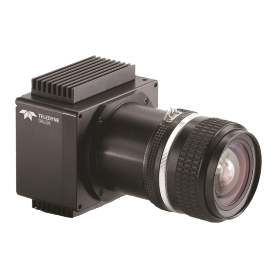
Summary of Contents for Teledyne DALSA Piranha 2 P2-2x-40 Series
- Page 1 P2-2x-xxx40, P2-4x-xxx40, P2-2x-xxx30 Camera User’s Manual Revised 5/4/2011 10:27:00 AM 4-May-11 03-032-00493-14 www.teledynedalsa.com...
- Page 2 Teled yne DALSA. About Teledyne Technologies and Teledyne D ALSA, Inc. Teled yne Technologies is a lead ing provid er of sophisticated electronic subsystem s, instrum entation and com m unication prod ucts, engineered system s, aerospace engines, and energy and pow er generation system s.
-
Page 3: Table Of Contents
3.17 Generating Test Patterns ............................39 3.18 Monitoring the Camera ............................. 40 3.19 Rebooting the Camera ............................... 41 3.20 Setting the Pre-trigger .............................. 41 Optical, Mechanical, and Thermal Considerations _________________________________ 43 4.1 Mechanical Interface ..............................43 4.2 Optical Interface ................................47 03-032-00493-14 Teledyne DALSA... - Page 4 C3 Command Format and Examples ..........................63 C4 Networking Mode ................................. 64 C5 Error Handling ................................67 C6 Camera Parameter Screen ............................70 C7 Commands ..................................73 DC Offset De-rating Curve _________________________________________________ 79 Revision History ________________________________________________________ 81 Index _______________________________________________________________ 85 03-032-00493-14 Teledyne DALSA...
-
Page 5: Introduction To The Piranha 2 Line Scan Camera
8 or 10-bit ou tpu t from 10-bit d igitization • 1024, 2048, and 4096 p ixels, 10µm x 10µm , and 4096, 6144 and 8192 pixels, 7m x 7m , 100% fill factor • Line rates u p to 65kH z 03-032-00493-14 Teledyne DALSA... - Page 6 Electronics m anu factu ring inspection Postal/ parcel sorting H igh perform ance d ocu m ent scanning/ im age lift N arrow and large w eb inspection H igh-end ind u strial inspection 03-032-00493-14 Teledyne DALSA...
-
Page 7: Image Sensors
N = 1024 or 2048 CR1B, CR2B, CRLAS T VS S Relative pos ition of package P in 1 Figure 2: IT-P1 4k Image Sensor (2k, 4k (10 µm), 4 tap models) Relative position of package Pin 1 N=2048 or 4096 03-032-00493-14 Teledyne DALSA... -
Page 8: Camera Performance Specifications
FPN , PRN U and noise. If you operate the cam era at faster line rates, su ch as 10kH z or greater, the am ou nt of d ark cu rrent w ill be red u ced by 10x or greater. 03-032-00493-14 Teledyne DALSA... - Page 9 24.4 8192, 2 o/ p kH z 7.15 8192, 4 o/ p kH z 18.6 Tem perature Front plate Tem perature °C Tem perature d rift before °C recalibration (recom m end ation) Sensor Alignm ent 03-032-00493-14 Teledyne DALSA...
- Page 10 . Typical resu lts are the average valu es obtained w ith at a 1kH z line rate and 30°C. Maxim u m resu lts represent the w orst case resu lts from any cam era operating at 50°C w ith a 1kH z line rate. 03-032-00493-14 Teledyne DALSA...
- Page 11 Measu rem ents taken at m axim u m line rates. Exposu re control enabled to set the m axim u m integration tim e to 200 m icrosecond s. Refer to Ap pend ix D for DC Offset d e-rating cu rves. 03-032-00493-14 Teledyne DALSA...
- Page 12 Piranha 2 User’s Manual Figure 5: P2 Responsivity Responsivity, Nominal Gain 10µm pixels 7µm pixels 400 500 1000 Wavelength (nm) 03-032-00493-14 Teledyne DALSA...
-
Page 13: Camera Hardware Interface
Diagnostic LED (S ee section 3.18) +12V to +15V and Ground WARNING: It is extremely important that you apply the appropriate voltages to your camera. Incorrect voltages w ill damage the camera. See section 2.4 for more details. 03-032-00493-14 Teledyne DALSA... -
Page 14: Connectors, Pinouts, And Cables
PAIR11- inner shield Inner Shield inner shield Inner Shield *Exterior Overshield is connected to the shells of the connectors on both end s. **3M part 14X26-SZLB-XXX-0LC is a com plete cable assem bly, inclu d ing connectors. 03-032-00493-14 Teledyne DALSA... - Page 15 See Ap pend ix B for the com plete Cam era Link configu ration table, and refer to the Know led ge Center page on the Teled yne DALSA Web site (w w w .teled yned alsa.com / m v/ know led ge/ appnotes.asp x) for the official Cam era Link d ocu m ents. 03-032-00493-14 Teledyne DALSA...
-
Page 16: Power Supplies
DALSA cameras, which used the PRIN rising edg PRIN is an optional inpu t signal u sed for exposu re control (PRIN ). PRIN Indicates H igh Integration Pixel reset 03-032-00493-14 Teledyne DALSA... -
Page 17: Data Bus, Camera Link
Du e to flat-field correction calcu lations, certain d igital nu m bers w ill be u navailable w hen ou tpu tting 10 bits w ith flat-field correction enabled (i.e. you w ill experience m issing cod es). 03-032-00493-14 Teledyne DALSA... - Page 18 Pixels below threshold LSB Pixels below threshold Derivative line sum LSB Use these values to focus the cam era. Generally, the greater the sum the greater the Derivative line sum Mid im age contrast Derivative line sum MSB 03-032-00493-14 Teledyne DALSA...
-
Page 19: Timing
Piranha 2 User’s Manual 2.7 Timing Figure 6. Piranha 2 Overview Timing Showing Input and Output Relationships Figure 7. Piranha 2 Fixed (Programmed) Integration Timing with External EXSYNC 03-032-00493-14 Teledyne DALSA... - Page 20 . The PRIN signal m ust be held a m inim um tim e after the EXSYN C falling ed ge to avoid losing the integrated charge tw PR_LOW Minim um Low tim e to assure com plete 2,000 +/ - 200 03-032-00493-14 Teledyne DALSA...
- Page 21 Fixed Integration Tim e m od e of operation 2,000 for variable exsync frequency. 138033 (8K2T) tREADOUT Is the num ber of pixels per tap tim es the 33, 792 (4K4T) read out clock period . Pretrigger = 0. 67,584 (4K2T) 33,792 (2K2T) 16,896 (1K2T) 03-032-00493-14 Teledyne DALSA...
-
Page 22: Camera Link Serial Communication
Cam era featu res can be controlled throu gh the Cam era Link™ serial com m u nication (LVDS, 9600 bau d ). The serial interface u ses sim ple ASCII-based protocol. The follow ing chapter d escribes how to configu re the cam era u sing the serial interface. 03-032-00493-14 Teledyne DALSA... -
Page 23: Software Interface: How To Control The Camera
C6 Cam era Param eter Screen on p age 70. 3.2 Command Format • A carriage retu rn (CR) end s each com m and . • Valu es in squ are brackets are optional. 03-032-00493-14 Teledyne DALSA... -
Page 24: Processing Chain
–5d b in calibrated m od e and 6d B in u ncalibrated m od e. When sw itching betw een calibrated and u ncalibrated m od es, the cam era au tom atically u ses the correspond ing valu e. 03-032-00493-14 Teledyne DALSA... -
Page 25: Startup
To restore the last saved u ser settings and the FPN and PRN U coefficients, u se the rus . com m and Factory Settings User Settings / EEROM restore w rite / restore Current Session 03-032-00493-14 Teledyne DALSA... -
Page 26: Setting Baud Rate
8-bit using ports A/ B and D/ E for d ual processor config uration 10-bit, using A/ B/ C and D/ E/ F for d ual processor configuration gcp . To obtain the cu rrent d ata m od e, u se the com m and 03-032-00493-14 Teledyne DALSA... -
Page 27: Setting The Video Mode
(m od e 2 only) to set the line rate and / or (m od e 2 or 6), to set the exposu re tim e. Refer to Setting Line Rate and Setting Exposu re Tim e below for d etails. 03-032-00493-14 Teledyne DALSA... - Page 28 To read the current line rate frequency, use the com m and gcp. If you enter an invalid line rate frequency, the valid range of values w ill be d isplayed. Related Com m and s: sem, set Exam ple: ssf 3000 03-032-00493-14 Teledyne DALSA...
-
Page 29: Setting A Region Of Interest
This inform ation is also u sed for collecting line statistics for calibrating the cam era. 03-032-00493-14 Teledyne DALSA... - Page 30 . The cam era d isplays the Min., Max., and Mean statistics. If you are u sing a region of interest, the cam era d isplays the statistics for the region of interest only. 03-032-00493-14 Teledyne DALSA...
-
Page 31: Optimizing Offset Performance
Optim izing offset perform ance in the analog d om ain allow s you to achieve a better signal-to-noise ratio (d ynam ic range) than you w ou ld achieve by trying to optim ize the offset in the d igital d om ain. 03-032-00493-14 Teledyne DALSA... - Page 32 . Use the ssg com m and to correct for th is. See section 3.13 Setting Gains for d etails on the ssg com m and . Exam ple: ssb 0 20 03-032-00493-14 Teledyne DALSA...
- Page 33 10 bit: 4 to 400DN See section 3.11 Returning Vid eo Inform ation for m ore inform ation on line averages This com m and sets offset in uncalibrated m od e (svm 0). N otes: Exam ple: cao 0 100 03-032-00493-14 Teledyne DALSA...
-
Page 34: Setting Gains
This fu nction requ ires a constant light inpu t w hile it execu tes. This featu re is beneficial for achieving a com m on ou tpu t level for m u ltiple cam eras in a system . 03-032-00493-14 Teledyne DALSA... -
Page 35: How To Calibrate The Camera
(balance target) for flat, w hite ou tpu t. Vid eo ou tpu t is set slightly above the brightest pixel (d ep end ing on offset su btracted ). 03-032-00493-14 Teledyne DALSA... - Page 36 Dark calibration is u sed to rem ove the fixed analog offset from the vid eo p ath. It is recom m end ed you repeat the calibration w hen a tem peratu re change greater than 10°C occu rs. 03-032-00493-14 Teledyne DALSA...
- Page 37 These restrictions are all tested w ithin the calibration algorithm and the cam era w ill report an inform al m essage cod e if any of these cond itions cou ld not be m et. 03-032-00493-14 Teledyne DALSA...
-
Page 38: Setting And Reading Fpn Coefficients
To set the FPN coefficient, u se the com m and : Syntax: sfc i i Syntax Elem ents: The pixel num ber from 1 to the pixel count. Coefficient value in a range from 0 to 127. Exam ple: sfc 10 50 03-032-00493-14 Teledyne DALSA... -
Page 39: Setting And Reading Prnu Coefficients
0 and 255 for 8-bit d ata Use the m od es, or 0 to 1023 for 10-bit d ata m od es. 03-032-00493-14 Teledyne DALSA... -
Page 40: Monitoring The Camera
Monitors current line rate Value Function Disable selected task Enable selected task N ote: by d efau lt all m onitoring tasks are enabled except voltage m o nitoring. Example: enable all monitoring tasks wed 0 1 03-032-00493-14 Teledyne DALSA... -
Page 41: Rebooting The Camera
A pre-trigger m ay be requ ired for som e fram e grabbers. To set the pre-trigger, u se the com m and : sp i Syntax: Syntax Elem ents: Pretrigger value from 0 to 15. Exam ple: sp 10 03-032-00493-14 Teledyne DALSA... - Page 42 Piranha 2 User’s Manual 03-032-00493-14 Teledyne DALSA...
-
Page 43: Optical, Mechanical, And Thermal Considerations
10°C of stead y state. If you r system cannot perform flat-field correction after w arm -u p consid er the recom m end ed m ethod s of red u cing d ark cu rrent and overall cam era tem peratu res (see below ). 03-032-00493-14 Teledyne DALSA... - Page 44 Both m ethod s— either cond u ction throu gh heat sinking, or convection throu gh air flow — greatly red u ce d ark cu rrent and w ill im prove you r system perform ance. 03-032-00493-14 Teledyne DALSA...
- Page 45 24.9 46.81 (2x) 49.3 41.6 53.8 (2x) 78.0 (2X) 78.0 (2x) (2x) 85.0 Units: mm M3x0.5 (4x) Camera assembly with 7.5 (2X) 70.0 (2X) Camera assembly with F-mount lens adapter C-mount lens adapter Scale (1:2) Scale (1:2) 03-032-00493-14 Teledyne DALSA...
- Page 46 M3x0.5 - 6H P OWER 42.50±0.18 13.0 5.0 deep Pixel 1 7.5 (2x) 61.0 (2x) (4x) 16.0 10.0 22.9 6.56±0.25 3.5 (2x) 69.0 Optical distance (active area to front M3x0.5 - 6H plate mount surface) 6.0 deep (4x) 03-032-00493-14 Teledyne DALSA...
-
Page 47: Optical Interface
For exam ple, 5J/ cm can be achieved by exposing 5m W/ cm for 1m s ju st the sam e as exposing an intensity of 5W/ cm for 1s. 03-032-00493-14 Teledyne DALSA... - Page 48 (d esired object resolu tion size). By sim ilar triangles, the m agnification is alternatively given by: These equ ations can be com bined to give their m ost u sefu l form : 03-032-00493-14 Teledyne DALSA...
-
Page 49: Compliance
Follow these specific gu id elines to ensu re best perform ance: • Keep Cam era Link cables as short as p ossible. • Ensu re that all cable shield s have 360 electrical connection to the connector. • Fasten and secu re all connectors. 03-032-00493-14 Teledyne DALSA... - Page 50 Piranha 2 User’s Manual 03-032-00493-14 Teledyne DALSA...
-
Page 51: Ccd Handling Instructions
H ow ever, the friction betw een the ru bber and the w ind ow m ay prod u ce electrostatic charge that m ay d am age the sensor. To avoid ESD d am age and 03-032-00493-14 Teledyne DALSA... -
Page 52: Cleaning The Sensor Window
5. Wipe the w ind ow carefu lly and slow ly. 6. When cleaning long linear sensors, it m ay be easier to w ip e along the w id th (i.e. as opp osed to the length) of the sensor. 03-032-00493-14 Teledyne DALSA... -
Page 53: Troubleshooting
(EXSYN C or PRIN ). PRIN PRIN is an optional inpu t signal u sed to control exposu re control (PRIN ). 03-032-00493-14 Teledyne DALSA... -
Page 54: Troubleshooting Using The Serial Interface
(refe r to the u ser cao or sao com m and s. Und er specifications). Ad ju st the analog offset u sing the light cond itions, you shou ld receive a valu e. 03-032-00493-14 Teledyne DALSA... -
Page 55: Specific Solutions
Do not attach w ires to u nu sed pins. Verify that the cam era is not receiving spu riou s inpu ts (e.g. EXSYN C or PRIN , if cam era is in exposu re m od e that regu lates external signals). 03-032-00493-14 Teledyne DALSA... - Page 56 Probe the ou tpu t lines w ith an oscilloscope. Disconnect the d igital cable from the cam era and check the d igital signals at the ou tpu t of the cam era. Ensu re that the correct valu es 03-032-00493-14 Teledyne DALSA...
- Page 57 If you have verified that you r exposu re tim e is consistent and patterns of low frequ ency intensity variations still occu r, ensu re that you are u sing a DC or high frequ ency light sou rce. 03-032-00493-14 Teledyne DALSA...
- Page 58 Piranha 2 User’s Manual 03-032-00493-14 Teledyne DALSA...
-
Page 59: Camera Link™ Reference
All fou r enable signals m u st be provid ed by the cam era on each Channel Link chip. All u nu sed d ata bits m u st be tied to a know n valu e by the cam era. For m ore inform ation on 03-032-00493-14 Teledyne DALSA... - Page 60 Pow er w ill not be provid ed on the Cam era Link connector. The cam era w ill receive pow er throu gh a sep arate cable. Cam era m anu factu rers d efine their ow n pow er connector, cu rrent, and voltage requ irem ents. 03-032-00493-14 Teledyne DALSA...
-
Page 61: Emc Declaration Of Conformity
Waterloo, ON , CAN ADA Date of Issu e October 2003 N am e and Signatu re Hank Helmond of au thorized person Quality Manager, Teledyne D ALSA Corp. This Declaration correspond s to EN 45 014. 03-032-00493-14 Teledyne DALSA... - Page 62 Piranha 2 User’s Manual 03-032-00493-14 Teledyne DALSA...
-
Page 63: Communications Protocol
The cam era w ill an sw er each com m and w ith either "OK >" or "Error x: Error Message >". The ">" is alw ays the last character sent by the cam era. Command Format command_long/short_form [parameters…] CR Example: to set the gain to –3.5dB on all taps set_gain 0 –3.5 03-032-00493-14 Teledyne DALSA... -
Page 64: C4 Networking Mode
The netw ork com m and is an ord inary cam era com m and p refixed by a netw ork p refix. N etw ork prefixes alw ays start w ith the colon character ":" and are follow ed im m ed iately 03-032-00493-14 Teledyne DALSA... - Page 65 The controlling softw are m u st w ait for a reply from the cam era before send ing the next com m and . Cam era w ill not reply to the Broad cast com m and . 03-032-00493-14 Teledyne DALSA...
- Page 66 To enable/ d isable cam era m essages u nrelated to the execu ted com m and , su ch as snm i . initialization and m onitoring task m essages, u se the com m and Value Function Enable m essages, d efault Disable m essages 03-032-00493-14 Teledyne DALSA...
-
Page 67: C5 Error Handling
Start value m ust be an od d num ber less than the even num bered end value Cam era m em ory check failure Mem ory test of external RAM failed 03-032-00493-14 Teledyne DALSA... - Page 68 Unable to calibrate offset. Tap Analog offset could not be calibrated because tap num ber specified in cao num ber outsid e ROI. com m and is outsid e region of interest. 03-032-00493-14 Teledyne DALSA...
- Page 69 WARN IN G: External PRIN Exposure Mod e 2: external PRIN not not d etected d etected WARN IN G: Analog gain is Current analog gain setting is out of over/ und er the specification specification 03-032-00493-14 Teledyne DALSA...
-
Page 70: C6 Camera Parameter Screen
Analog Offset: 308 324 304 292 Analog offset value set w ith the sao and cag com m and . The cag com m and is available only in uncalibrated m od e (svm 1). See section 3.12 03-032-00493-14 Teledyne DALSA... - Page 71 . SETTINGS COMMON TO CALIBRATED AND UNCALIBRATED MODES: System Gain: 0 0 0 0 Digital gain value set w ith the ssg com m and . See section 3.13 Setting Gains for d etails. 03-032-00493-14 Teledyne DALSA...
- Page 72 Setting Line Rate and Exposure Mod e for details. States w hether an end of line End-Of-Line Sequence: sequence is turned on or off. Set using the eol com m and . See section 3.17 Generating Test Patterns for d etails. 03-032-00493-14 Teledyne DALSA...
-
Page 73: C7 Commands
Values range from 64 to 251DN for 8-bit m od e and 256 to 1007DN for 10-bit. correction_set_sam ple Set num ber of line sam ples averaged for pixel coefficient calculations or for output of 03-032-00493-14 Teledyne DALSA... - Page 74 Set the pixel range for read ing end -of-line statistic and for the region of pixels used in the cag, cao, gl, gla, ccf, and ccp com m and s. Pixel start and end values in a range from 1 to 03-032-00493-14 Teledyne DALSA...
- Page 75 PRN U correction. The first param eter is the tap selection 1 to 4, 0 for all taps. The second param eter is the offset in a range from 0 to 511. Use in calibrated m od e only. 03-032-00493-14 Teledyne DALSA...
- Page 76 Set the PRN U coefficient. The first param eter is the pixel num ber w ithin the range 1 to 8192. The second param eter is a specified value w ithin the range 0 to 511w here: 03-032-00493-14 Teledyne DALSA...
- Page 77 Write all current pixel coefficients to EEROM. w rite_user_settings Write all of the user settings to EEROM except pixel coefficients w hich are w ritten using the wpc com m and . 03-032-00493-14 Teledyne DALSA...
- Page 78 Piranha 2 User’s Manual 03-032-00493-14 Teledyne DALSA...
-
Page 79: Dc Offset De-Rating Curve
Ad d ing cooling to red u ce tem peratu re. Refer to the Therm al Managem ent section on page 43 for m ore inform ation. Operating the cam era at higher line rate and averaging or d iscard ing the extra lines 03-032-00493-14 Teledyne DALSA... - Page 80 27.5 36.5 65.5 Camera internal Temperature C Notes: Cam era am bient tem peratu re is ap proxim ately 15°C less than the internal cam era tem peratu re. Cam era gain is 10d B 03-032-00493-14 Teledyne DALSA...
-
Page 81: Revision History
It is now referenced to section 3.18. In section 3.16, page 39, and Append ix B, All Available Com m and s table, ad d ed equation for d eterm ining the PRN U coefficient for the spc com m and . 03-032-00493-14 Teledyne DALSA... - Page 82 4096 - 2/ 4 o/ p 500/ 700 4096(10um ) - 2 o/ p 600 4096(10um ) - 4 o/ p 800 6144 - 2/ 4 o/ p 600/ 800 8192 - 2/ 4 o/ p 620/ 840 03-032-00493-14 Teledyne DALSA...
- Page 83 4 to 1. Becau se the m axim um per -pixel digital gain is 2x, the cam era w ill not be able to com pensate for extrem ely non -uniform light.‖ 03-032-00493-14 Teledyne DALSA...
- Page 84 Piranha 2 User’s Manual 03-032-00493-14 Teledyne DALSA...
-
Page 85: Index
17 d ark patches, 56 PRIN , 16 Data Bus, 17 interface d ata m od e, 26 m echanical, 43 d ebugging, 18, 39, 53 optical, 47 d igital d ata, 17 serial, 23 03-032-00493-14 Teledyne DALSA... - Page 86 9 voltage operational status of cam era, 40 m easurem ent, 41 optical interface, 47 output m od e, 26 w arning m essages, 40 w hite light calibration, 37 perform ance, 9 pixel statistics, 29 03-032-00493-14 Teledyne DALSA...
Need help?
Do you have a question about the DALSA Piranha 2 P2-2x-40 Series and is the answer not in the manual?
Questions and answers