
Related Manuals for Teledyne NIRvana System


Summary of Contents for Teledyne NIRvana System
- Page 1 ® NIRvana System Manual 4411-0137 Issue 7 May 13, 2019 www.princetoninstruments.com...
- Page 2 Trenton, NJ 08619 TEL: 800-874-9789 / 609-587-9797 FAX: 609-587-1970 All rights reserved. No part of this publication may be reproduced by any means without the written permission of Teledyne Princeton Instruments. Printed in the United States of America. NIRvana, IntelliCal, PVCam, and LightField are registered trademarks of Teledyne Digital Imaging US, Inc..
-
Page 3: Table Of Contents
Care and Cleaning of a NIRvana System ........ - Page 4 NIRvana System Manual Issue 7 Attaching a Lens to a C-Mount Adapter ........38 4.5.1...
- Page 5 Issue 7 Table of Contents 8.11 Readout ............. . 74 8.11.1 Region of Interest (ROI) .
- Page 6 Installation Procedure ........103 Adjustable C- to Teledyne Acton Research SpectraPro Series Spectroscopy-Mount Adapter105 C.3.1...
- Page 7 ....... . . 100 Figure C-1: Flange Mount to Teledyne Acton Research SpectraPro...
- Page 8 Table 3-1: NIRvana System Installation Procedure......27 Table 10-1: Issues with Recommended Troubleshooting Guidelines... . 85 Table A-1: NIRvana:640 Sensor Specifications .
-
Page 9: Chapter 1: About This Document
WinSpec 2.6 Spectroscopy Software User Manual 4411-0046 WinView 2.6 Imaging Software User Manual Current issues of Teledyne Princeton Instruments’ manuals are available for downloaded from: ftp://ftp.piacton.com/Public/Manuals/Princeton Instruments Current issues of Teledyne Acton Research manuals are available for downloaded from: ftp://ftp.piacton.com/Public/Manuals/Acton... -
Page 10: Document Organization
Appendix B, Outline Drawings Includes an outline drawing of the C-mount NIRvana camera and the power supply. • Appendix C, Spectrograph Adapters Provides information and procedures required to install a C-mount or spectroscopy-mount camera to Teledyne Acton Research SpectraPro Series spectrograph. -
Page 11: Conventions Used In This Manual
Chapter 1 About this Document • Appendix D, C-Mount to Spec-Mount Procedure This appendix provides information necessary to replace the C-mount nose on a NIRvana camera with a spectroscopy-mount nose. • Appendix E, Calibration Charts This appendix provides the following calibration charts for use with the NIRvana camera •... -
Page 12: Safety Information
WARNINGS! If the NIRvana camera system is used in a manner not specified by Teledyne Princeton Instruments, the protection provided by the equipment may be impaired. 2. If the wall outlet is damaged, the protective grounding could be disconnected. Do not use damaged equipment until its safety has been verified by authorized personnel. -
Page 13: Precautions
Chapter 1 About this Document 1.5.2 Precautions To prevent permanently damaging the system, please observe the following precautions: • If you are using high-voltage equipment (such as an arc lamp) with your camera system, be sure to turn the camera power ON LAST and turn the camera power OFF FIRST. - Page 14 NIRvana System Manual Issue 7 This page is intentionally blank.
-
Page 15: Chapter 2: Nirvana Camera System
Chapter 2: NIRvana Camera System This chapter provides an introduction to, and overview information about, Teledyne Princeton Instruments’ NIRvana camera system. Figure 2-1 shows those items that are typically included as part of a standard NIRvana Camera System. Figure 2-1:... -
Page 16: Nirvana Camera
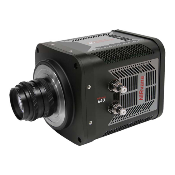
NIRvana system with the rest of an experiment. Figure 2-2: Typical NIRvana Camera In addition, the internal controller converts analog optical data acquired by the CCD sensor into digital data which is then delivered to the host computer and data acquisition software being used. -
Page 17: Ccd Sensor
Chapter 2 NIRvana Camera System 2.1.1 CCD Sensor The NIRvana camera incorporates a 640 x 512 CCD (20 x 20 m pixels) InGaAs focal plane array (FPA) that is equipped with four-port differential readouts. The sensor’s excellent response and outstanding sensitivity in the 0.9 m -1.7 m spectrum make it particularly well suited for Near-InfraRed (NIR) imaging applications. -
Page 18: Internal Fan
NOTE: The coolant circulator can be Teledyne Princeton Instruments’ CoolCUBE or any commercially available circulator that is capable of continuously pumping a 50:50 mixture of room temperature (23ºC) water and ethylene... -
Page 19: Rear-Panel Connectors
Label Description Shutter ® LEMO connector provides the shutter drive pulses for driving a Teledyne Princeton Instruments-supplied 25 mm external shutter. Camera power must be OFF before connecting to, or disconnecting from, this connector. Power 24 V (9.5 A max) input and TEC control from power supply. -
Page 20: Standard Cables
MCX to BNC 6050-0540 Two MCX to BNC adapter cables are provided Varies Adapter with the NIRvana system. These connect to the EXT SYNC and the LOGIC OUT connectors on the rear of the NIRvana. Power 6050-0596 Connects the NIRvana camera to the power supply. -
Page 21: Coolant Hoses
Purchase Order Number; • Camera Serial Numbers This information is useful when contacting Teledyne Princeton Instruments Customer Support. NIRvana System User Manual The NIRvana System User Manual describes how to install, configure, and use a NIRvana camera and its components. -
Page 22: Optional Accessories
Other optional items may be available. For complete information about available options for the NIRvana camera system, contact Teledyne Princeton Instruments. 2.6.1 Application Software Teledyne Princeton Instruments offers a number of data acquisition software packages for use with NIRvana camera systems, including: ® •... -
Page 23: Coolant Circulator
• PVCAM PVCAM is Teledyne Princeton Instruments’ standard 32-bit software interface for cooled CCD cameras. It is a library of functions that can be used to control and acquire data from the camera when a custom application is being written. -
Page 24: Optical Adapters
Figure 2-4: Optional Optical Adapters C-Mount to Spectroscopy Adjustable C-Mount to Mount Adapter Spectroscopy Mount Adapter Care and Cleaning of a NIRvana System From time to time, NIRvana cameras may require minor cleaning. 2.7.1 Detector Window • Never remove the detector’s front window. Ice will form immediately, destroying the sensor. -
Page 25: Repairs
NIRvana Camera System Repairs Because the NIRvana camera system contains no user-serviceable parts, repairs must be performed by Teledyne Princeton Instruments. Should your system need repair, contact Teledyne Princeton Instruments customer support for instructions. For contact information, refer to Contact Information on page 124. - Page 26 NIRvana System Manual Issue 7 This page is intentionally blank.
-
Page 27: Installation
Figure 3-4 provide an overview of the sequence of actions required to install a NIRvana system and prepare to gather data. Refer to the indicated references for detailed information. Table 3-1: NIRvana System Installation Procedure (Sheet 1 of 2) -
Page 28: Figure 3-1: Typical Imaging Experiment Layout: Air-Cooled Camera
NIRvana System Manual Issue 7 Table 3-1: NIRvana System Installation Procedure (Sheet 2 of 2) For additional information, refer Action to… 13. When the system reaches temperature lock, wait an additional 20 Chapter 6, LightField First Light minutes and then begin acquiring data in focus mode. -
Page 29: Figure 3-2: Typical Spectroscopy Experiment Layout: Air-Cooled Camera
Chapter 3 Installation Figure 3-2: Typical Spectroscopy Experiment Layout: Air-cooled Camera Power Cable Power Supply 100 – 240 V Ethernet Cable GigE Host Computer Camera Gigabit Ethernet Card Spectrometer Sample Figure 3-3: Typical Imaging Experiment Layout: Air/Liquid-cooled Camera Power Cable Power Supply 100 –... -
Page 30: Figure 3-4: Typical Spectroscopy Experiment Layout: Air/Liquid-Cooled
NIRvana System Manual Issue 7 Figure 3-4: Typical Spectroscopy Experiment Layout: Air/Liquid-cooled Camera Power Cable Power Supply 100 – 240 V Host Computer Ethernet Cable Gigabit GigE Ethernet Card Coolant Camera Circulator Coolant Hoses 100 – 240 V Coolant Coolant... -
Page 31: System Setup
If damage is not apparent but camera or controller specifications cannot be achieved, internal damage may have occurred in shipment. Save the original packing materials so you can safely ship the camera system to another location or return it to Teledyne Princeton Instruments for repairs if necessary. -
Page 32: Checking The Equipment And Parts Inventory
NIRvana System Manual Issue 7 Checking the Equipment and Parts Inventory Verify that all required equipment and parts necessary to set up the NIRvana system have been received. A complete system consists of: • Standard Equipment: — Camera — Power Supply —... -
Page 33: System Requirements
Chapter 4 System Setup System Requirements This section summarizes NIRvana System requirements. 4.3.1 Environmental Requirements Storage temperature: 55°C • • Operating environment temperature: +5ºC to +30ºC; the environment temperature at which system specifications can be guaranteed is +20ºC Relative humidity 50%; non-condensing •... -
Page 34: Host Computer Specifications
NIRvana System Manual Issue 7 4.3.4 Host Computer Specifications Host Computer specifications vary based on which data acquisition software is being used. This section provides minimum host computer specifications by software package. NOTES: Computers and operating systems undergo frequent revisions. The following information is intended to provide an approximate indication of the computer requirements. -
Page 35: Lightfield Host Computer Requirements
Chapter 4 System Setup 4.3.4.2 LightField Host Computer Requirements When running LightField data acquisition software, the host computer must satisfy the following requirements: a. 64-bit Operating System: ® — Windows Vista , or ® — Windows 7 ® • 2 GHz Pentium 4 (minimum);... -
Page 36: Data Acquisition Software Installation
Figure 4-1: Typical LightField Installation Wizard Dialog 5. After the installation finishes, reboot the host computer. 6. Connect the NIRvana system components to the host computer and power them 7. Launch LightField and activate it according to on-screen instructions. 8. Begin experiment configuration. -
Page 37: Installing Winx
Chapter 4 System Setup 4.4.2 Installing WinX Perform the following procedure to install WinX on the host computer: NOTES: Install the GigE Adapter card BEFORE installing the WinView/32 or WinSpec/32 application software. 2. The interface cable between the camera and the host computer should remain disconnected until after WinView/32 or WinSpec/32 (version 2.5.25 or higher) has been completely installed. -
Page 38: Attaching A Lens To A C-Mount Adapter
NIRvana cameras for imaging applications incorporate an integrated C-mount adapter. Other mounts may be available. Consult the factory for specific information relating to your needs. For information about contacting Teledyne Princeton Instruments Customer Support, refer to Contact Information on page 124. -
Page 39: Adjusting A C-Mount Adapter
Chapter 4 System Setup Adjusting a C-Mount Adapter The NIRvana features an adjustable C-mount adapter that allows the focal depth to be changed. Perform the following procedure to adjust the C-mount adapter: Using the hex wrench supplied with the system (or a 0.050" hex wrench) loosen the setscrew securing the adapter. -
Page 40: Making The Camera-Circulator Connections For A Coolcubeii
NIRvana System Manual Issue 7 3. Use the hex wrench to tighten the setscrew to lock the adapter in place. NOTE: To lock the setscrew, the face of the adapter should be no more than 0.1" (2.5 mm) out from the front surface of the camera nose. - Page 41 Chapter 4 System Setup 4. Unscrew the reservoir cap located on top of the CoolCUBE and verify that the coolant reservoir contains coolant. If additional coolant is required, fill the tank with a 50:50 mixture of water and ethylene glycol. 5.
-
Page 42: Configure Default Lightfield Camera Parameters
NIRvana System Manual Issue 7 Configure Default LightField Camera Parameters Perform the following procedure to configure default system parameters in LightField: Verify that the NIRvana camera (and the associated spectrograph when configuring a spectroscopy system,) is connected to the host computer, and that associated power supplies for the camera and spectrograph (when applicable) are turned on. -
Page 43: Operation
Chapter 5: Operation Once the NIRvana camera has been installed as described in preceding chapters, operation of the camera is straightforward. For most applications, optimum performance is established using the Focus {Preview} mode, the camera’s target temperature is set, and once the camera’s temperature has stabilized actual data acquisition is performed in Acquire mode. -
Page 44: Winx On/Off Sequences
NIRvana System Manual Issue 7 Whether or not the data are displayed and/or stored depends on the data collection operation that has been selected in the application software: Focus { Preview } • This mode is typically used when setting up the system during First Light procedures. -
Page 45: Chapter 6: Lightfield First Light Procedure
Chapter 6: LightField First Light Procedure This chapter provides step-by-step instructions to verify initial system operation using LightField image acquisition software. Imaging Applications This section provides step-by-step instructions for acquiring an imaging measurement in LightField for the first time. The intent of this procedure is to help gain basic familiarity with the operation of the system and to show that it is functioning properly. -
Page 46: Figure 6-1: Typical Available Devices Area
NIRvana System Manual Issue 7 5. After LightField opens, you should see an icon representing your camera in the Available Devices area. In Figure 6-1, the camera shown is a NIRvana:640. Figure 6-1: Typical Available Devices Area 6. Drag the camera icon into the Experiment Devices area. See Figure 6-2. -
Page 47: Acquire Data
Chapter 6 LightField First Light Procedure 6.1.2 Acquire Data Perform the following procedure to acquire data: Just above Experiment Devices, click on the View tab to change to the display area. Figure 6-3. Figure 6-3: Typical View Area 2. Click Run to start Preview mode. -
Page 48: Shut Down Procedure
NIRvana System Manual Issue 7 3. Adjust the lens aperture, intensity scaling, and focus for the best image as viewed on the computer monitor. Imaging tips include: • Begin with the lens blocked off and then set the lens to the smallest possible aperture (i.e., the greatest f-stop number.) -
Page 49: Spectroscopy Applications
Set the spectrograph entrance slit width to minimum (10 m if possible). 2. Power ON the spectrograph. 3. Mount a light source such as a Teledyne Princeton Instruments Hg and Ne/Ar Dual Switchable light source in front of the entrance slit. -
Page 50: Figure 6-5: Available Devices Area
NIRvana System Manual Issue 7 4. Connect the shutter cable between the entrance slit shutter and NIRvana’s Shutter connector. • External Slit Shutter: A shutter assembly mounted externally to the spectrograph has shutter cable that plugs into the Shutter connector. -
Page 51: Verify The Setup
Chapter 6 LightField First Light Procedure 10. Drag each icon into the Experiment Devices area. See Figure 6-6. Figure 6-6: Experiment Devices Area The Experiment Settings stack on the left now displays several expanders. Because this is a new experiment, the default settings for the camera will be active. The Status bar located at the bottom of the window displays an icon for temperature status. -
Page 52: Rotational Alignment And Focus
When aligning accessories such as fibers, lenses, and optical fiber adapters, first align the spectrograph to the slit. Then align the accessory without disturbing the camera’s position. The following sections provide information and procedures necessary to rotationally align and focus a NIRvana system using LightField. -
Page 53: Rotational Alignment
View Area. Figure 6-7: Typical View Area 2. If you have not already done so, mount a light source such as a Teledyne Princeton Instruments IntelliCal light source at the front of the entrance slit. Any light source with line output can be used. -
Page 54: Figure 6-8: Alignment Spectrometer: Pre-Rotational Alignment
NIRvana System Manual Issue 7 4. Set the slit to 10 m. If necessary, adjust the Exposure Time to maintain optimum (i.e., near full-scale,) signal intensity. 5. Wait until the camera temperature locks at its default temperature. 6. Verify that the spectroscopy-mount adapter moves freely at the spectrograph. -
Page 55: Focus
Perform the following procedure to focus the system: NOTES: Although this procedure describes how to focus for a Teledyne Acton Research SP-2356i spectrograph, it is easily adapted to other spectrographs. 2. This procedure assumes that the camera and spectrograph have been turned on, appropriate icons... -
Page 56: Acquire Data
Focusing is accomplished depending on the spectrograph being used as follows: • Long focal-length spectrographs (e.g., a Teledyne Acton Research SP-2300) The mounting adapter includes a tube that slides inside another tube to move the camera in or out as required to achieve optimum focus. -
Page 57: Chapter 7: Winx First Light Procedure
Chapter 7: WinX First Light Procedure This chapter provides configuration information and procedures for a NIRvana system • Configure WinView/32 for imaging applications; and • Configure WinSpec/32 for spectroscopic applications. Imaging Applications This section provides step-by-step instructions for acquiring an imaging measurement in WinView/32. -
Page 58: Figure 7-1: Typical Hardware Setup Dialog: Controller/Camera Tab
NIRvana System Manual Issue 7 5. Configure the software parameters as follows: ► • Controller/Camera tab (Setup Hardware) These parameters should be automatically configured to the proper values for the system. — Controller type: This information is read from the camera. -
Page 59: Figure 7-2: Typical Detector Temperature Dialog
Chapter 7 WinX First Light Procedure Figure 7-2: Typical Detector Temperature Dialog NOTE: The Detector Temperature dialog will not display temperature information during data acquisition. ► ► • Experiment Setup Main tab (Acquisition Experiment Setup…): — Exposure Time: 50 ms —... -
Page 60: Verify The Setup
NIRvana System Manual Issue 7 7.1.2 Verify the Setup Perform the following procedure to verify the configuration and setup: When using WinView/32 and the computer monitor for focusing, select Focus from the Acquisition menu. Successive images will be sent to the monitor as quickly as they are acquired. -
Page 61: Spectroscopy Applications
An underlying assumption for the procedure is that the camera is to be operated with a spectrograph (e.g., a Teledyne Acton Research SpectraPro Series 2300 spectrograph,) on which it has been properly installed. -
Page 62: Figure 7-4: Typical Hardware Setup Dialog: Controller/Camera Tab
NIRvana System Manual Issue 7 3. Mount a light source such as a Teledyne Princeton Instruments IntelliCal Hg/Ne-Ar Dual Switchable light source in front of the entrance slit. 4. Connect the shutter cable between the entrance slit shutter and the NIRvana’s Shutter connector. -
Page 63: Figure 7-5: Typical Detector Temperature Dialog
Chapter 7 WinX First Light Procedure Figure 7-5: Typical Detector Temperature Dialog NOTE: The Detector Temperature dialog will not display temperature information during data acquisition. ► ► • Experiment Setup Main tab (Acquisition Experiment Setup…): — Exposure Time: 50 ms —... -
Page 64: Verify The Setup
NIRvana System Manual Issue 7 7.2.2 Verify the Setup Perform the following procedure to verify the configuration and setup: Turn on the light source at the spectrograph entrance slit. 2. In WinSpec, select Focus (on the Acquisition menu or on the Experiment Setup dialog) to begin data accumulation. -
Page 65: Rotational Alignment And Focus
Perform the following procedure to rotationally align the system: If you have not already done so, mount a light source such as a Teledyne Princeton Instruments IntelliCal light source at the spectrograph’s entrance slit. Any light source with a line output can be used. - Page 66 NIRvana System Manual Issue 7 3. Verify that the slit is set to a minimum of 10 m. If necessary, adjust the Exposure Time to maintain optimum (i.e., near full-scale) signal intensity. 4. Wait until the camera temperature locks at its default temperature.
-
Page 67: Focus
Focusing is accomplished depending on the spectrograph being used as follows: • Long focal-length spectrographs (e.g., a Teledyne Acton Research SP-2300) The mounting adapter includes a tube that slides inside another tube to move the camera in or out as required to achieve optimum focus. -
Page 68: Acquire Data
NIRvana System Manual Issue 7 7.2.4 Acquire Data After the NIRvana has been properly aligned and focused, perform the following procedure to acquire data: If running in Focus mode, halt data acquisition. 2. Make any required changes to the experiment setup and/or software parameters. -
Page 69: Exposure And Signal
Chapter 8: Exposure and Signal This chapter discusses factors that affect exposure, readout, and digitization of incoming signals. By understanding the exposure, readout, and digitization factors, and making adjustments to software settings, the signal-to-noise ratio can be maximized. Sensor Architecture A focal plane array (FPA) such as the one in NIRvana is a matrix of photodiodes bonded to a readout circuit on an IC chip. -
Page 70: Built-In Gain Correction
NIRvana System Manual Issue 7 Built-In Gain Correction The NIRvana camera is factory calibrated at -80°C for all speeds and gains to do a column-by-column gain correction. This, coupled with background subtraction, helps remove the vertical fixed pattern in the image due to column amplifier differences. If improved pixel-by-pixel correction is desired, refer to Section 8.7, Flat Field... -
Page 71: Background Subtraction
Chapter 8 Exposure and Signal Background Subtraction Background subtraction can be used to remove or reduce the impact of fixed pattern noise when acquiring data. The technique requires that a background image be acquired, stored, and selected as the background file to be used in background-subtracted data acquisition. -
Page 72: Dark Charge
CAUTION! If a sudden change is observed in the baseline signal, there may be excessive humidity in the camera vacuum enclosure. Turn off the camera and contact Teledyne Princeton Instruments Customer Support. Refer to Contact Information on page 124 for complete contact information. -
Page 73: 8.10 Cleaning
Chapter 8 Exposure and Signal 8.10 Cleaning The basic cleaning function is implemented by clean cycles. These cycles start when the camera is turned on and a clean pattern is programmed into the camera. Their purpose is to remove charge that accumulates on the sensor while the camera not acquiring data (i.e., exposing and reading out the sensor.) Figure 8-3 illustrates the... -
Page 74: 8.11 Readout
NIRvana System Manual Issue 7 8.11 Readout Three factors to be considered with regard to sensor readout are: • Region of Interest (ROI) Selection; Defining a Region of Interests allows a user-specified region on the sensor to be read out and the collected data saved. The remaining data is read out and discarded. -
Page 75: Software Binning
Chapter 8 Exposure and Signal Example The following descriptions assume that the actual incoming light level is identical in both instances. The numbers used do not reflect the actual values for NIRvana and do not reflect actual detector performance. • 1 {Low} requires 1750 electrons to generate one ADU. -
Page 76: Digitization Rate {Speed
CAUTION! If a sudden change in the baseline signal is observed, there may be excessive humidity in the detector vacuum enclosure. Turn off the camera and contact Teledyne Princeton Instruments Customer Support for instructions. 8.12.3 Readout Time In WinX, the calculated readout time is reported on the Readout Time box (via the Acquisition menu.) In LightField, readout time is reported on the Sensor Readout... -
Page 77: Advanced Topics
Chapter 9: Advanced Topics Previous chapters discussed the configuration of hardware and software for basic operation. This chapter discusses the following topics associated with experiment synchronization: • Shutter Control Modes; • Timing {Trigger Response} Modes; • LOGIC OUT Control. Depending on the data acquisition software being used, experiment synchronization parameters are located as follows: ►... -
Page 78: Timing {Trigger Response} Modes
NIRvana System Manual Issue 7 Timing {Trigger Response} Modes NIRvana’s Timing {Trigger Response} modes for Full Frame operation are: • Free Run {No Response}; • External Sync {Readout Per Trigger}; • Bulb Trigger {Expose During Trigger Pulse}; • Trigger Start {Start On Single Trigger}. -
Page 79: Free Run {No Response
Chapter 9 Advanced Topics 9.2.2 Free Run {No Response} In this mode, the camera ignores any external triggers and all settings are obtained from the setup parameters, making the duration of each exposure time constant and the interval times between exposures constant. NOTE: In this timing mode, all shutter modes behave the same way. -
Page 80: External Sync {Readout Per Trigger} With Continuous Cleans
NIRvana System Manual Issue 7 9.2.4 External Sync {Readout Per Trigger} with Continuous Cleans {Clean Until Trigger} Timing Another timing mode supported by NIRvana is Continuous Cleans {Clean Until Trigger}. In addition to the standard cleaning of the sensor that occurs after the camera has been enabled, this mode removes any accumulated charge from the sensor up until the moment the External Sync pulse is received. -
Page 81: Bulb Trigger {Expose During Trigger Pulse} Timing
Chapter 9 Advanced Topics Once an External Sync {Readout Per Trigger} pulse has been received, cleaning of the sensor halts as soon as the current clean cycle has completed (a clean cycle reads out the entire sensor and then discards the data,) and frame data collection begins. •... -
Page 82: Trigger Start {Start On Single Trigger
NIRvana System Manual Issue 7 Figure 9-7 illustrates the timing diagram for Bulb Trigger {Expose During Trigger Pulse} mode with the following configuration settings: • Three exposure sequence; • No Pre Open {Open Before Trigger}; • No Continuous Cleans {Clean Until Trigger}. -
Page 83: Logic Out Control
Chapter 9 Advanced Topics LOGIC OUT Control This section provides information about the use of the Logic Out connector on the rear of the NIRvana. The signals at these connectors can be used to monitor camera operation or synchronize with external equipment. The TTL-compatible logic level output (i.e., 0 to +3.3 V ) from the LOGIC OUT connector on the rear panel can be used to monitor camera status and control external... - Page 84 NIRvana System Manual Issue 7 Additional related signals and configuration settings include: • Expose (Effective) {Exposing} This level is at a logic high during the effective exposure time. This exposure time equals the read out time in frame transfer mode when the exposure time is less than the readout time.
-
Page 85: Chapter 10: Troubleshooting
Do not attach or remove any cables while the camera system is powered on. Recommended troubleshooting guidelines are available for many issues that may occur while working with a NIRvana system. Refer to Table 10-1 for additional information. Table 10-1: Issues with Recommended Troubleshooting Guidelines Issue Refer to…... -
Page 86: 10.1 Acquisition Has Started But Data Display Is Empty
NIRvana System Manual Issue 7 10.1 Acquisition Has Started but Data Display is Empty If you have started a data acquisition but no data are appearing in the data display, stop the acquisition. Look at the Data Display title bar and verify that the first number in the Region of Interest (ROI) is evenly divisible by 4. -
Page 87: 10.2 Acquisition Started But Viewer Contents Do Not Update
A change in the baseline signal is normal if the temperature, gain, or speed setting has been changed. If this occurs when none of these settings have been changed, there may be excessive humidity in the camera vacuum enclosure. Turn the camera off and contact Teledyne Princeton Instruments Customer Support. Refer to Contact Information... -
Page 88: 10.4 Camera Stops Working
Turn the circulator back on. — If there are no problems, proceed to step 8. — If the problem persists, turn off the system, and contact Teledyne Princeton Instruments Customer Support. Refer to Contact Information on page 124 for complete contact information. -
Page 89: 10.6 Cooling Troubleshooting
Contact the factory to make arrangements for returning the camera to the support facility. 1. Teledyne Princeton Instruments guarantees a permanent vacuum for the life of a NIRvana camera. -
Page 90: 10.7 Device Is Not Found
20200-20202. The ports may be closed as part of the local network’s standard computer security (e.g., an anti-virus program or a firewall.) However, these ports must be open before LightField can detect a Teledyne Princeton Instruments GigE camera. Contact your local IT specialist for assistance if necessary. -
Page 91: Winx Applications
Chapter 10 Troubleshooting 10.8.1 WinX Applications Perform the following procedure to restore an Ethernet network connection for WinX applications: Navigate to the directory in which the EbDriverTool32.exe is stored. NOTE: The file may also be named EbDriverTool.exe. The file is typically stored on the host computer within the default Pleora directory (or one of the subdirectories): C:\Program Files\Common Files\Pleora If the file cannot be located on the host computer, it may be downloaded from the... -
Page 92: Lightfield Applications
NIRvana System Manual Issue 7 10.8.2 LightField Applications Perform the following procedure to restore an Ethernet network connection for LightField applications: Navigate to the directory in which the EbDriverTool64.exe is stored. The file is typically stored on the host computer within the default Pleora directory... -
Page 93: Appendix A: System Specifications
Appendix A: System Specifications This appendix provides general information and specifications for a NIRvana system. For additional information, refer to: • Appendix B, Outline Drawings, on page 97; • The device-specific data sheet. NOTE: All specifications are subject to change. -
Page 94: Quantum Efficiency
• Gig-E: Gigabit Ethernet connector. • Shutter: LEMO® connector provides the shutter drive pulses for driving a Teledyne Princeton Instruments-supplied 25 mm external shutter. Camera power must be OFF before connecting to or disconnecting from this connector. Cable not supplied. -
Page 95: Power Specifications And Information
Appendix A System Specifications • Ext Sync: 0 to +3.3 VDC logic level input to allow data acquisition to be synchronized with external events. Trigger edge can be positive- or negative-edge as configured in software. An MCX-to-BNC adapter cable is included with system. -
Page 96: Available Mounts And Adapters
LightField application software and manual; • WinView or WinSpec application software and manual; • PICam software and manual (64-bit); • PVCAM software and manual (32-bit); • CoolCUBE coolant circulator. Contact Teledyne Princeton Instruments for information about options available for the NIRvana system. -
Page 97: Appendix B: Outline Drawings
Appendix B: Outline Drawings NOTE: All dimensions are listed in inches [mm]. Figure B-1: Outline Drawing: NIRvana:640 with C-Mount 0.625 15.88 0.620 15.74 1.725 43.82 1.755 44.58 7.62 193.66 7.40 187.84 3.13 79.53 1.150 29.21 0.69 CCD LOCATION WINDOW IN VACUUM SURFACE 0.476 12.08 WINDOW FRONT SURFACE... -
Page 98: Figure B-2: Outline Drawing: Nirvana:640 With Spectroscopy-Mount
NIRvana System Manual Issue 7 Figure B-2: Outline Drawing: NIRvana:640 with Spectroscopy-Mount... -
Page 99: Figure B-3: Outline Drawing: Nirvana Power Supply
Appendix B Outline Drawings Figure B-3: Outline Drawing: NIRvana Power Supply 9.82 2.15 4.29... -
Page 100: Figure B-4: Outline Drawing: Coolcube Ii
NIRvana System Manual Issue 7 Figure B-4: Outline Drawing: CoolCUBE... -
Page 101: Appendix C: Spectrograph Adapters
C-mount lenses. Cameras for spectroscopy applications are designed with two different bolt circle patterns to accommodate Teledyne Acton Research sliding tubes. Before mounting the camera to a Teledyne Acton Research Series spectrograph, you should follow the instructions in this appendix for attaching the appropriate spectrograph kit and sliding tube. -
Page 102: Flange-Mount To Teledyne Acton Research Spectrapro Spectroscopy
NIRvana System Manual Issue 7 Flange-Mount to Teledyne Acton Research SpectraPro Spectroscopy-Mount Adapter Figure C-1: Flange Mount to Teledyne Acton Research SpectraPro Spectroscopy-Mount Adapter Sliding Tube and Spacer Plate (supplied with spectrograph) Table C-2: Required Hardware: Flange-Mount to Teledyne Acton Research... -
Page 103: C-Mount To Teledyne Acton Research Spectrapro Spectroscopy-Mount
C-Mount to Teledyne Acton Research SpectraPro Spectroscopy-Mount Adapter Figure C-2: C-Mount to Teledyne Acton Research SpectraPro Spectroscopy-Mount Adapter Sliding Tube (supplied with spectrometer) Spacer Plate (Removed) Table C-3: Required Hardware: C-Mount to Teledyne Acton Research SpectraPro Spectroscopy-Mount Part Number Description 8401-071-01 Adapter Plate 8401-071-02 Threaded C-Mount Adapter Screw, 10-32 ... - Page 104 NIRvana System Manual Issue 7 10-32 ¼ 5. Use three (3) screws to secure sliding tube to the adapter plate. 6. Gently insert the sliding tube into the spectrograph and fasten with the setscrews. NOTE: Adapter parts are machined to provide a tight fit. If you need...
-
Page 105: Installation Procedure
Appendix C Spectrograph Adapters Adjustable C- to Teledyne Acton Research SpectraPro Series Spectroscopy-Mount Adapter Figure C-3: Adjustable C- to Teledyne Acton Research SpectraPro Series Spec-Mount Adapter Table C-4: Required Hardware: Adjustable C-Mount to Teledyne Acton Research Spectra Pro Spec-Mount Part Number... - Page 106 NIRvana System Manual Issue 7 This page is intentionally blank.
-
Page 107: Appendix D: C-Mount To Spec-Mount Procedure
Appendix D: C-Mount to Spec-Mount Procedure This appendix provides information necessary to replace the C-mount nose on a NIRvana camera with a spectroscopy-mount nose. Required Parts and Tools The following items are required: • Tools: — 3/32 Hex Driver — 9/64 Hex Driver •... -
Page 108: Exploded Parts Diagrams/Views
NIRvana System Manual Issue 7 Exploded Parts Diagrams/Views Figure D-1 illustrates an exploded view of the C-mount bezel and the spectroscopy mount. Refer to this diagram as necessary. Figure D-1: Exploded Views of C-Mount/Bezel (L) and Spectroscopy-Mount (R) -
Page 109: Replacement Procedure
Appendix D C-Mount to Spec-Mount Procedure Replacement Procedure Perform the following procedure to replace the C-mount with the spectroscopy-mount: If the camera is connected to its power supply, verify the power supply is turned off. Disconnect it from the camera. 2. -
Page 110: Figure D-4: Camera With Bezel Removed
NIRvana System Manual Issue 7 7. Carefully lift the bezel and screws up and off of the camera. See Figure D-4. Figure D-4: Camera with Bezel Removed 8. Verify the 3 ID x 0.070 O-ring is in the groove around the puck. See Figure D-5. -
Page 111: Figure D-6: Installed Spectroscopy-Mount
Appendix D C-Mount to Spec-Mount Procedure 12. Place the 2-5/8 ID x 3/32 O-ring in the groove on the face the spectroscopy flange. Figure D-6. Figure D-6: Installed Spectroscopy-Mount 13. Place the dust cover over the flange to protect the window. 14. - Page 112 NIRvana System Manual Issue 7 This page is intentionally blank.
-
Page 113: Appendix E: Calibration Charts
Appendix E: Calibration Charts This appendix provides the following calibration charts for use with the NIRvana camera: • HG Calibration Spectrum for NIRvana; • Ne-Ar Calibration Spectrum for NIRvana. -
Page 114: Figure E-1: Hg Spectrum: Nirvana 1.7/Sp-2500
NIRvana System Manual Issue 7 Figure E-1: Hg Spectrum: NIRvana 1.7/SP-2500... -
Page 115: Figure E-2: Ne/Ar Spectrum: Nirvana 1.7/Sp-2500
Appendix E Calibration Charts Figure E-2: Ne/Ar Spectrum: NIRvana 1.7/SP-2500... - Page 116 NIRvana System Manual Issue 7 This page is intentionally blank.
-
Page 117: Appendix F: Winspec/32/Lightfield Cross Reference
Appendix F: WinSpec/32/LightField Cross Reference This appendix provides cross reference information for terminology used within the WinSpec/32 and LightField application software packages. WinSpec/32-to-LightField Terminology Refer to Table F-1 for a list of WinSpec/32 terms and their corresponding LightField terms. Table F-1: WinSpec/32-to-LightField Cross Reference (Sheet 1 of 2) WinSpec/32 Term LightField Term... - Page 118 NIRvana System Manual Issue 7 Table F-1: WinSpec/32-to-LightField Cross Reference (Sheet 2 of 2) WinSpec/32 Term LightField Term Logic Out: Shutter Output Signal: Shutter Open Minimum Block Size Final Section Height Normal Shutter Normal (Shutter) Number of Blocks Final Section Count...
-
Page 119: Lightfield To Winspec/32
Appendix F WinSpec/32/LightField Cross Reference LightField to WinSpec/32 Refer to Table F-2 for a list of LightField terms and their corresponding WinSpec/32 terms. Table F-2: LightField-to-WinSpec/32 Cross Reference (Sheet 1 of 2) LightField Term WinSpec/32 Term Active Area: Bottom Margin Post-Dummy Rows Parallel to Shift Register Active Area: Left Margin Pre-Dummy Shift Register Columns... - Page 120 NIRvana System Manual Issue 7 Table F-2: LightField-to-WinSpec/32 Cross Reference (Sheet 2 of 2) LightField Term WinSpec/32 Term Preview Focus Quality Readout Port Readout Per Trigger External Sync Readout Per Trigger (DIF) Single Trigger (DIF) Sensor Readout Region expander functions...
-
Page 121: Warranty And Service
(1) year after shipment. During this period, Teledyne Princeton Instruments will repair the product or, at its sole option, repair or replace any defective part without charge to you. You must deliver the entire product to the Teledyne Princeton Instruments factory or, at our option, to a factory-authorized service center. -
Page 122: Sealed Chamber Integrity Limited 12 Month Warranty
(1) year from shipment. Teledyne Princeton Instruments does not warrant that the function of the software will meet your requirements or that operation will be uninterrupted or error free. -
Page 123: Owner's Manual And Troubleshooting
3. All warranty service must be made by the Teledyne Princeton Instruments factory or, at our option, an authorized service center. 4. Before products or parts can be returned for service you must contact the Teledyne Princeton Instruments factory and receive a return authorization number (RMA.) Products or parts returned for service without a return authorization evidenced by an RMA will be sent back freight collect. -
Page 124: Contact Information
In no event shall Teledyne Princeton Instruments’ liability exceed the cost of the repair or replacement of the defective product or part. - Page 125 This page is intentionally blank.
- Page 126 info@princetoninstruments.com USA +1 877-474-2286 | France +33 (1) 60 86 03 65 | Germany +49 (0) 89 660 7793 | UK & Ireland +44 (0) 1628 472 346 Singapore +65 6408 6240 | China +86 10 659 16460 | Japan +81 (3) 5639 2741...
Need help?
Do you have a question about the NIRvana System and is the answer not in the manual?
Questions and answers