
Related Manuals for Teledyne TS-M4096


Summary of Contents for Teledyne TS-M4096
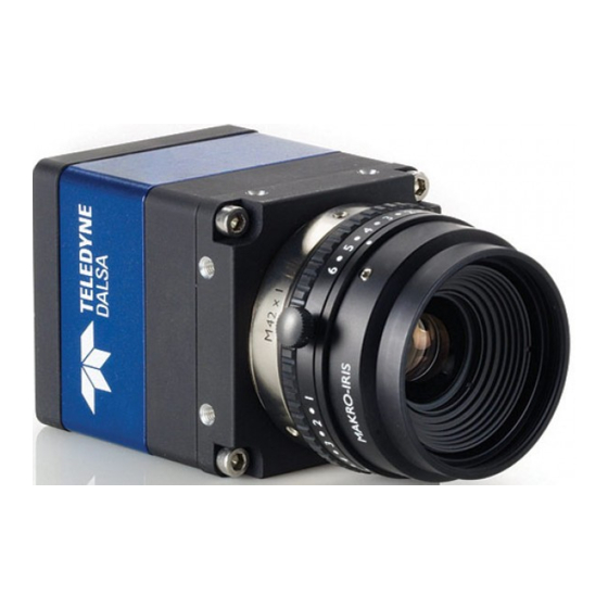
- Page 1 ™ Genie TS Series Camera User’s Manual Genie TS Framework 1.20 sensors | cameras | frame grabbers | processors | software | vision solutions P/N: CA-GENM-TSM00 www.teledynedalsa.com...
- Page 2 All information provided in this manual is believed to be accurate and reliable. No responsibility is assumed by Teledyne DALSA for its use. Teledyne DALSA reserves the right to make changes to this information without notice. Reproduction of this manual in whole or in part, by any means, is prohibited without prior permission having been obtained from Teledyne DALSA.
-
Page 3: Table Of Contents
APERA PPLICATION ESCRIPTION ..............12 AMERA PECIFICATIONS VERVIEW EMI, Shock and Vibration Certifications ..........13 : TS-M4096, TS-C4096, TS-M3500, TS-C3500, TS- ENSOR ERFORMANCE M2500, TS-C2500 ................14 Sensor Specifications ................14 Sensor Cosmetic Specifications .............15 Spectral Responsivity: Monochrome............16 Effective Quantum Efficiency: Monochrome ..........16 Spectral Responsivity: Color ..............17 Effective Quantum Efficiency: Color ............17... - Page 4 GigE Server Verification ...............32 GigE Server Status ................33 ..........33 PTIMIZING THE ETWORK DAPTER USED WITH ENIE Running the Network Configuration Tool ..........33 .................34 UICK EST WITH XPERT About the User Defined Camera Name ...........36 TS F ............37 ILENT NSTALLATION OF ENIE RAMEWORK ...............38...
- Page 5 Width and Height Features for Partial Scan Control ........ 112 Vertical Cropping (Partial Scan) ..............112 Maximum Frame Rate (fps) Examples (TS-M4096 – DALSA Vouvray) ....113 Maximum Frame Rate (fps) Examples (TS-M3500 – DALSA Vouvray) ....113 Maximum Frame Rate (fps) Examples (TS-M2500 – DALSA Vouvray) ....113 Maximum Frame Rate (fps) Examples (TS-M2048 –...
- Page 6 ETAILS Link-Local Address (LLA) ..............150 DHCP (Dynamic Host Configuration Protocol) ........151 Persistent IP ..................152 TECHNICAL SPECIFICATIONS..............153 : TS-M4096, TS-M3500, TS-M2500, TS-C4096, ECHANICAL PECIFICATIONS TS-C3500, TS-C2500 ................. 153 M42x1 to Nikon F Bayonet Adapter ............154 M42x1 to C-Mount Adapter ..............155 : TS-M1920, TS-M2048 ........
- Page 7 ADDITIONAL REFERENCE INFORMATION ..........166 ................166 ELECTION VERVIEW Lens Mount Types ................166 Lenses for the Genie TS with M42 or with Nikon F-mount adapter .... 166 Lenses for the Genie TS (5M) with the optional C-Mount Adapter ..... 167 Lenses for the Genie TS with CS-Mount (2M or 4M)........
-
Page 8: Genie Ts Series Overview
Genie cameras combine standard gigabit Ethernet technology (supporting GigE Vision 1.2 or 2.0 dependent on firmware) with the Teledyne DALSA Trigger-to-Image-Reliability framework to dependably capture and transfer images from the camera to the host PC. Genie TS cameras are available in a number of models implementing different sensors, image resolutions, and feature sets, either in monochrome or color versions. -
Page 9: Genie Application Advantages
Genie Application Advantages Optimized, rugged design GigE Vision 1.2 compliant, or version 2.0 compliant when using JPEG compression firmware Gigabit Ethernet (GigE) interconnection to a computer via standard CAT5e or CAT6 cables Supports connection to the host computer NIC through a GigE network switch ... -
Page 10: Genie Firmware Design Versions
Genie cameras with specific features to support a variety of embedded operations. The following table lists the Genie cameras available (updated for each release) with the firmware design versions supported by that model. Firmware updates for all Genie TS models are available for download from the Teledyne DALSA web site [ www.teledynedalsa.com/imaging/support/downloads ]. -
Page 11: Part Numbers And Software Requirements
This manual covers the Genie TS monochrome and color models summarized below. This table groups models by color mode, resolution, and other physical parameters. New models area added to this manual as they are released by Teledyne DALSA. See "Camera Specifications" on page 12 for details of each Genie TS model. - Page 12 Teledyne DALSA Software Platform For Microsoft Windows: Genie TS Framework composed of the Sapera network Included with Genie TS Imaging Package and GigE Vision Imaging Driver. distribution (via web download) Alternative Genie TS Firmware Designs such as JPEG and Fast Mode.
-
Page 13: Gige Vision Sapera Application Description
GenApi module of the GenICam™ specification. For more information see www.genicam.org. The Teledyne DALSA GigE Vision Module provides a license free development platform for Teledyne DALSA GigE hardware or Sapera vision applications. Additionally supported are Sapera GigE Vision applications for third party hardware with the purchase of a GigE Vision Module license, or the Sapera processing SDK with a valid license. -
Page 14: Camera Specifications Overview
Camera Specifications Overview Camera Controls Synchronization Modes Free running, External triggered, Software trigger through Ethernet Exposure Modes Programmable in increments of 1µs minimum (in µs) is model specific maximum is 16 seconds Pulse controlled via Trigger pulse width. Trigger Inputs Opto-isolated, 2.4V to 24V typical, 16mA min. -
Page 15: Emi, Shock And Vibration Certifications
Electrical Interface Input Voltage +12 to +24 Volts DC (+20%/- 10%) at 0.6 Amp minimum Supports the Power Over Ethernet standard. (PoE Class 3 as per IEEE 802.3af) Power Dissipation < 6W (Vouvray and CMOSIS sensors), < 7W (AnaFocus sensor) Output Data Configuration Gigabit Ethernet with PAUSE Frame support (as per IEEE 802.3x) Data and Control... -
Page 16: Sensor Performance: Ts-M4096, Ts-C4096, Ts- M3500, Ts-C3500, Ts-M2500, Ts-C2500
End of Exposure to Readout 20 μs Horizontal Line Time 26.125 μs (TS-M4096), 22.925 μs (TS-M3500), 16.525 μs (TS-M2500) 26.125 μs (TS-C4096), 22.925 μs (TS-C3500), 16.525 μs (TS-C2500) Readout Time Horizontal Line Time (max) x (lines in frame +1) in μs Pixel Size 6.0µm x 6.0µm... -
Page 17: Sensor Cosmetic Specifications
‡ Specifications calculated according to EMVA-1288 standard, using white LED light Sensor Cosmetic Specifications The following table lists the current cosmetic specifications for DALSA Vouvray models TS-M4096, TS-M3500, TS-M2500, TS-C4096, TS-C3500, and TS-C2500. Blemish Specifications Maximum Number of Blemish Description Defects Hot/Dead Pixel defects †††... -
Page 18: Spectral Responsivity: Monochrome
Spectral Responsivity: Monochrome 20.0 Spectral Responsivity Gain: Analog = 1.0 15.0 10.0 Wavelength (nm) Effective Quantum Efficiency: Monochrome The quantum efficiency graph describes the fraction of photons at each wavelength that contribute charge to the pixel. Effective Spectral Quantum Efficiency Gain: Analog = 1.0 Wavelength (nm) 16 ... -
Page 19: Spectral Responsivity: Color
Spectral Responsivity: Color 10.0 Spectral Responsivity Gain: Analog = 1.0 Wavelength (nm) Effective Quantum Efficiency: Color Effective Spectral Quantum Efficiency Gain: Analog = 1.0 Wavelength (nm) An near infrared cutoff filter (~650nm) is recommended to obtain good visible light color separation when using light with an IR component. -
Page 20: Sensor Performance : Ts-M1920, Ts-C1920, Ts-M2048, Ts-C2048
Sensor Performance: TS-M1920, TS-C1920, TS- M2048, TS-C2048 The sensor description below (CMOSIS models) provides a specification table and response graphics. The graph describes the sensor response to different wavelengths of light (excluding lens and light source characteristics). Sensor Specifications Item / Feature Specification Camera Models &... -
Page 21: Sensor Cosmetic Specifications
† Dynamic Range Test Conditions Exposure 100µs 0% Full Light Level All Corrections OFF †† SNR Test Conditions Exposure 600µs 80% Full Light Level FFC OFF (no factory FFC provided) Defective pixels replacement ON with 15% ‡... -
Page 22: Spectral Response
Spectral Response Models TS-M1920 and TS-M2048 are each available in two versions as listed below. The normal version sensors are processed on 5µm epi-layer wafers while the E12 version sensors are processed on 12µm epi-layer wafers. As seen in the following graph, E12 sensors have an increased spectral response above 600nm. -
Page 23: Sensor Performance: Ts-M2560
Sensor Performance: TS-M2560 The sensor description below (AnaFocus models) provides a specification table and response graphics. The graph describes the sensor response to different wavelengths of light (excluding lens and light source characteristics). Sensor Specifications Item / Feature Specification Camera Models TS-M2560 Sensor Used Lince 5M... -
Page 24: Sensor Cosmetic Specifications
Sensor Cosmetic Specifications Blemish Specifications Maximum Number of Blemish Description Defects Hot/Dead Pixel defects ††† Typical 0.0025% Any pixel that deviates by ±20% from the average of Max 0.005% neighboring pixels at 50% saturation including pixel stuck at 0 and maximum saturated value. Spot defects none Grouping of more than 8 pixel defects within a sub-area of 3x3... -
Page 25: Focus
Sensor Relative Response: VOUVRAY vs. CMOSIS vs. AnaFocus The following graphs show the relative sensitivity between sensors, for an equal exposure time and ignoring sensor signal noise. Two gain factors (nominal and maximum) were used as indicated. VOUVRAY, ANAFOCUS and CMOSIS sensors response at 1500µs exposure with nominal gain 4.19 6.25 8.38 10.46... -
Page 26: Connecting The Genie Ts Camera
Connect the Genie TS Camera Connecting a Genie TS to a network system is independent to whether the Teledyne DALSA Sapera LT package or a third party GigE Vision development package is used. -
Page 27: Connectors
A Micro-D sub 25 connector for camera power (or auxiliary power), plus trigger, strobe and general I/O signals. Teledyne DALSA provides an optional breakout cable (part number G2- IOPC-MD25F). See “25-pin Micro-D type Connector Details” on page 158 for connector pinout specifications. -
Page 28: Led Indicators
LED Indicators The Genie has one multicolor LED to provide a simple visible indication of camera state and the RJ45 Ethernet connector has two LEDs for network status conditions. These are described below. Network Status Indicators The Genie TS RJ45 Ethernet connector has two LEDS which display standardized information, defined as follows: Ethernet Connector LEDs Color... -
Page 29: Led States On Power Up
IP address. The DHCP server then provides the Genie an IP address. The Teledyne DALSA Network Configuration tool, installed with the Teledyne DALSA Network Imaging Package, provides a DHCP server which is easily enabled on the NIC used with the Genie TS (refer to the Teledyne DALSA Network Imaging Package user's manual). -
Page 30: Preventing Operational Faults Due To Esd
0 volt return line is not necessarily connected to earth ground. Teledyne DALSA has performed ESD testing on Genie cameras using an 8 kilovolt ESD generator without any indication of operational faults. The two following methods, either individually or together will prevent ESD problems. -
Page 31: Using Genie Ts With Sapera Api
DALSA Network Imaging Package user's manual). Genie also can connect through a Gigabit Ethernet switch. When using VLAN groups, the Genie and controlling computer must be in the same group (refer to the Teledyne DALSA Network Imaging Package user's manual). ... -
Page 32: Sapera Lt Library Windows Installation
The procedure will prompt for acceptance of the installation folder for the Genie files. Optional: If the Teledyne DALSA Sapera LT SDK package is not used, click to install the Genie TS firmware and user manuals only. Follow the on screen prompts. -
Page 33: Camera Firmware Updates Or Changes
Genie TS models. The following table lists the current firmware file sets available for the various Genie TS models, and where the “xx” in the file name denotes the firmware build version. Current version firmware files are posted on the Teledyne DALSA support web site. DALSA Vouvray models TS-M4096, TS-M3500, TS-M2500 GenieTS_Mono_Dalsa-5M_8M_12M_STD-Firmware_3CA10.xx.cbf... -
Page 34: Application Development Header Files
Application Development Header Files Teledyne DALSA provides header files for developers managing Genie TS LUT data and chunk payload data as supported by GigE Vision 1.2. These files are installed by default in the folder [drv]:\Program Files\Teledyne DALSA\Genie TS\Developer Support Files\. -
Page 35: Gige Server Status
Most Gigabit network interface controllers (NIC) allow user modifications to parameters such as Adapter Buffers and Jumbo Frames. These should be optimized for use with the Genie during the installation. Refer to the Teledyne DALSA Network Imaging package manual for optimization information. -
Page 36: Quick Test With Camexpert
Genie camera for a minimum 10 seconds. Refer to the Teledyne DALSA Network Imaging Module manual for more detailed information on using this tool. As shown below, the Network Configuration tool can quickly verify and modify the network configuration of the imaging system. - Page 37 Refer to the Teledyne DALSA Network Imaging package manual if error messages are shown in the Output Messages pane. But first, increase the value of the Genie Interpacket Delay feature available from the GigE Vision Transport Layer Category group in CamExpert. An increase from default may correct errors with NIC interfaces that do not have adequate performance.
-
Page 38: About The User Defined Camera Name
When using CamExpert, multiple Genie TS cameras on the network are seen as different "Genie_TS-xxxxx" devices as an example. Non Teledyne DALSA cameras are labeled as “GigEVision Device”. Click on a device user name to select it for control by CamExpert. -
Page 39: Silent Installation Of Genie Ts Framework
Silent Installation of Genie TS Framework The Genie TS Framework installation can be integrated within a developer's installation procedure. The silent installation mode allows the Genie Framework installation to proceed without the need for mouse clicks from a user. Two steps are required: ... -
Page 40: Windows Embedded 7 Installation
Windows Embedded 7 Installation Windows Embedded 7 is not officially supported by Teledyne DALSA due to the number of possible configurations. However, Sapera LT and other Teledyne DALSA products should function properly on the Windows Embedded 7 platform provided that the required components are installed. -
Page 41: Operational Reference
Operational Reference Using CamExpert with Genie TS Cameras The Sapera CamExpert tool is the interfacing tool for GigE Vision cameras, and is supported by the Sapera library and hardware. When used with a Genie TS camera, CamExpert allows a user to test most of the operating modes. - Page 42 Device pane: View and select from any installed GigE Vision or Sapera acquisition device. After a device is selected CamExpert will only present parameters applicable to that device. Parameters pane: Allows viewing or changing all acquisition parameters supported by the acquisition device.
-
Page 43: Camexpert View Parameters Option
In this category the number of features shown are identical whether the view is Beginner, Expert, or Guru. Features listed in the description table but tagged as Invisible are usually for Teledyne DALSA or third party software usage—not typically needed by end user applications. Also important, Genie TS cameras are available in a number of models implementing different sensors and image resolutions which may not support the full feature set defined in this category. -
Page 44: Camera Information Feature Descriptions
Camera Information Feature Descriptions The following table describes these parameters along with their view attribute and in which device version the feature was introduced. Additionally the Device Version column will indicate which parameter is a member of the DALSA Features Naming Convention (indicated by DFNC), versus the GenICam Standard Features Naming Convention (SFNC not shown). - Page 45 Display Name Feature & Values Description Device Version & View Manufacturer Name DeviceVendorName Displays the device vendor name. (RO) 1.00 Beginner Model Name DeviceModelName Displays the device model name. (RO) 1.00 Beginner Device Version DeviceVersion Displays the device version. This tag will also 1.00 highlight if the firmware is a beta or custom design.
- Page 46 Device Built-In Self Test deviceBIST Command to perform an internal test which will 1.00 determine the device status. (W) DFNC Beginner Device Built-In Self Test deviceBISTStatus Return the status of the device Built-In Self test. 1.00 Status Possible return values are device-specific. Beginner Passed Passed...
-
Page 47: Camera Configuration Selection Dialog
Camera Configuration Selection Dialog CamExpert provides a dialog box which combines the features to select the camera power up state and for the user to save or load a camera state from Genie memory. Camera Power-up Configuration The first drop list selects the camera configuration state to load on power-up (see feature UserSetDefaultSelector). -
Page 48: Sensor Control Category
Parameters in black are user set in CamExpert or programmable via an imaging application. Features listed in the description table but tagged as Invisible are usually for Teledyne DALSA or third party software usage—not typically needed by end user applications. Also important, Genie TS cameras are available in a number of models implementing different sensors and image resolutions which may not support the full feature set defined in this category. -
Page 49: Sensor Control Feature Descriptions
Sensor Control Feature Descriptions The following table describes these features along with their view attribute and device framework version. For each feature the device version may differ for each camera sensor available and whether the camera is programmed with Standard firmware (STD), JPEG firmware (JPG), or Fast firmware (FST). - Page 50 Active Active Activates the auto-brightness mode when the AcquisitionStart or AcquisitionArm command is received. Auto-Brightness Sequence autoBrightnessSequence Specifies the processing order for the auto-brightness algorithm. Gain, Iris, and Exposure are adjusted sequentially, in the selected order, to achieve the auto- brightness target value.
- Page 51 Auto-Brightness Minimum Time autoBrightnessAlgoMinTimeActivation Specifies the time delay between an image brightness Activation change from the autoBrightnessTarget and when compensation of Gain/Exposure/Iris starts. This eliminates repetitive adjustments of short term brightness variations. < DFNC Expert > Auto-Brightness Convergence autoBrightnessAlgoConvergenceTime Specifies the approximate maximum time the Time autoBrightnessAlgorithm should take to compensate the image brightness as defined by the...
- Page 52 Auto-Exposure Time Min Value exposureAutoMinValue Sets the minimum exposure time value allowed by the user, in microseconds, for the Auto-Exposure function. < DFNC Expert > Auto-Exposure Time Max Value exposureAutoMaxValue Sets the maximum exposure time value allowed by the user, in microseconds, for the Auto-Exposure function. <...
- Page 53 Reset_EOE Reset_EOE This mode is similar to the standard Reset mode described above. The difference being that this mode requires a continuous and fixed frequency trigger and is used with the Auto-Brightness or Auto-Exposure modes. The readout occurs only at the end of exposure. Use ExposureTimeMaxValue to define the maximum possible exposure time which is followed by the frame readout.
- Page 54 Auto-Gain Min Value gainAutoMinValue Sets the minimum gain multiplier value for the automatic gain algorithm. The automatic gain function is an amplification factor applied to the video signal to obtain the auto-brightness target value. < DFNC Expert > Black Level Selector BlackLevelSelector Selects which Black Level to adjust using the Black Level features.
- Page 55 Active Active Enable the MultiSlopeSensorResponseMode feature. MultiSlope Knee Selector multiSlopeKneeSelector Selects which multi-slope knee position to set. V1.10 - STD — < DFNC Expert > Knee Point 1 KneePoint1 Selects the first knee point. Knee Point 2 KneePoint2 Selects the second knee point. MultiSlope Knee Position X multiSlopeKneePositionX Sets the Multi-Slope Knee position as a % of the...
-
Page 56: Bayer Mosaic Pattern
Bayer Mosaic Pattern The Genie TS Color camera outputs raw Bayer image data using the mosaic pattern shown below. Teledyne DALSA Sapera CamExpert tool interprets the raw Bayer output when the user enables the Pre-Processing Software Bayer Decoder. Bayer Mosaic Pattern and the CamExpert processing function to decode the Genie TS Color Gain and Black Level Control Details The Genie TS series of cameras provide gain and black level adjustments. -
Page 57: Exposure Controls Details
Exposure Controls Details Exposure Control modes define the method and timing of controlling the sensor integration period. The integration period is the amount of time the sensor is exposed to incoming light before the video frame data is transmitted to the controlling computer. ... -
Page 58: External Trigger Programmable Exposure
External Trigger Programmable Exposure Also known as “Edge Pre-select” exposure. See the timing diagram below. An external trigger edge initiates the exposure process. The user programmable delay (exposureDelay) from valid trigger edge to start of exposure is camera model specific. -
Page 59: Synchronization Timing
Synchronization Timing Genie TS supports two types of sensor synchronization used to align the exposure to sensor timing: Synchronous Mode: Exposure is synchronous to the line timing of the sensor. Exposure time steps are 1µs and the readout can be concurrent to the exposure for the fastest possible frame rate. -
Page 60: Exposure Alignment: Synchronous_Eoe & Reset_Eoe
Exposure Alignment: Synchronous_EOE & Reset_EOE These two exposure modes are specifically designed for cases where multiple cameras using independent auto-exposure modes are driven by a common exposure trigger and require synchronized frame readouts to the host system. An Example Setup: ... -
Page 61: Auto-Brightness With Frame Luminance Averaging
Enable all Auto-Brightness features by setting autoBrightnessMode to active (live acquisition must be off). This master switch feature only activates the auto-brightness, auto-exposure, and auto-gain controls but doesn’t enable the processing. The features autoBrightnessSequence, autoBrightnessTargetSource, autoBrightnessTarget, autoBrightnessTargetRangeVariation, and autoBrightnessAlgorithm can remain at their default settings for this demo. -
Page 62: Auto-Gain
Auto-Gain An alternative method of automating exposure control is by varying the Genie TS Digital Gain. The user needs to note that the digital gain stage is limited to a small positive multiplier and will have the side effect of increasing digital noise. ... - Page 63 Curve (1): Represents a pixel that is overexposed quickly, long before the end of the exposure time. The user decides to ignore these areas of the image. Curve (2): Represents a pixel that becomes overexposed shortly before the end of the exposure time.
-
Page 64: Example Of Multi-Slope Operation
Example of Multi-Slope Operation With multi-slope mode enabled, for a given user set exposure time, the user chooses the points of exposure where the sensor response reduces and becomes nonlinear(multiSlopeKneePositionY), plus the point where the sensor response returns to normal (multiSlopeKneePositionX). This effectively acts to extend the dynamic range. - Page 65 Changes in lighting will require changes to multi-slope parameters to maintain maximum optimal sensor dynamic range, for a given exposure time. Example use of Multi-Slope Mode multiSlopeKneePositionY as a percentage of Full Well 100% max DN Exposure Time 100% of Set Exposure Time multiSlopeKneePositionX as a percentage of Exposure Time...
-
Page 66: Key Points Concerning Multi-Slope Mode
Sensor characteristics change above the knee point. Increasing the dynamic range above the multiSlopeKneePositionY setting implies a nonlinear sensor response. Overall Analog Gain is reduced to 67% (models TS-M4096, TS-M3500, TS-M2500) of the default gain when enabled, therefore increasing the pixel well capacity at the sensor level. ... -
Page 67: I/O Control Category
Parameters in black are user set in CamExpert or programmable via an imaging application. Features listed in the description table but tagged as Invisible are usually for Teledyne DALSA or third party software usage—not typically needed by end user applications. Also important, Genie TS cameras are available in a number of models implementing different sensors and image resolutions which may not support the full feature set defined in this category. -
Page 68: I/O Control Feature Descriptions
I/O Control Feature Descriptions The following table describes these features along with their view attribute and minimum camera firmware version required. Additionally the Device Version column will indicate which parameter is a member of the DALSA Features Naming Convention (indicated by DFNC), versus the GenICam Standard Features Naming Convention (SFNC not shown). - Page 69 Level High LevelHigh The trigger is considered valid on the high level … Level Low LevelLow The trigger is considered valid on the low level … 1.00 Trigger Delay TriggerDelay Specifies the delay in microseconds to apply after Beginner receiving the trigger and before activating the triggerEvent.
- Page 70 1.00 Line Status All LineStatusAll Returns the current status of all available line Expert signals, at time of polling, in a single bitfield. The order is Line1, Line2, Line3, ... (RO) 1.00 Line Inverter LineInverter Controls whether to invert the polarity of the Beginner selected input or output line signal.
- Page 71 Falling Edge FallingEdge Specifies that the trigger is considered valid on the falling edge of the source signal. Any Edge AnyEdge Specifies that the trigger is considered valid on the falling or rising edge of the source signal. 1.00 Output Line Pulse Delay outputLinePulseDelay Sets the delay (in µs) before the output line pulse Beginner...
-
Page 72: I/O Module Block Diagram
I/O Module Block Diagram Trigger Mode Details Genie TS image exposures are initiated by an event. The trigger event is either the camera's programmable internal clock used in free running mode, an external input used for synchronizing exposures to external triggers, or a programmed function call message by the controlling computer. -
Page 73: Input Line Details
Input Line Details The general purpose input line signals are connected to I/O lines 1 through 4 and have the following features for control or status indication. Feature set: LineSelector (RW), LineName (RO), linePinAssociation (RO), LineFormat (RO), LineMode (RO), lineDetectionLevel (RW), lineDebouncingPeriod (RW), LineInverter (RW), LineStatus (RO). -
Page 74: Counter And Timer Control Category
Parameters in black are user set in CamExpert or programmable via an imaging application. Features listed in the description table but tagged as Invisible are usually for Teledyne DALSA or third party software usage—not typically needed by end user applications. Also important, Genie TS cameras are available in a number of models implementing different sensors and image resolutions which may not support the full feature set defined in this category. - Page 75 Display Name Feature & Values Description Device Version & View 1.00 Counter Selector counterSelector Selects the counter to configure. Expert Counter 1 Counter1 Select counter 1 DFNC 1.00 Counter mode counterMode Selects the counter mode. The selected Counter is Expert either Active or Disabled.
- Page 76 Falling Edge FallingEdge Starts counting on falling edge of the selected Line. Any Edge AnyEdge Starts counting on the falling or rising edge of the selected Line. 1.00 Counter Incremental counterIncrementalSource Select the event source which increments the Expert Source counter.
- Page 77 Rejected Frame Trigger InvalidFrameTrigger Reset on reception of the Invalid Frame Trigger. MultiFrame End Trigger FrameBurstEnd Reset on reception of the Frame Burst end. Line 1 Line1 Reset counter on the specified transition on line 1. See Input Signals Electrical Specifications. Line 2 Line2 Reset counter on the specified transition on line 2.
-
Page 78: Counter And Timer Group Block Diagram
Line 4 Trigger Line4 Start Timer on a transition of I/O Line 4 event. Timer 1 End Timer1End Start Timer on Timer End event. Counter 1 End Counter1End Start Timer on Counter 1 End event. 1.00 Timer Line Activation timerStartLineActivation Select the trigger activation mode which starts the Expert timer. -
Page 79: Example: Counter Start Source = Off
Example: Counter Start Source = OFF The counter starts on the counterReset Cmd. The counter continues unless a new counterReset Cmd is received, which then restarts the counter at 00. When Counter Reset Source= ‘Event’ or ‘CounterEnd’ the counter is reset to 00 but does not restart counting, until the next CounterReset Cmd. -
Page 80: Example: Counterstartsource = Event And Signal (Edge Base)
Example: CounterStartSource = EVENT and Signal (Edge Base) Example: CounterStartSource = Signal (Level Base) Example 1 78 Operational Reference Genie_TS_Series GigE Vision Camera... -
Page 81: Example: Counterstartsource = Line (Edge Base) Example 2
Example: CounterStartSource = Line (Edge Base) Example 2 Operational Reference 79 Genie_TS_Series GigE Vision Camera... -
Page 82: Advanced Processing Control Category
Parameters in black are user set in CamExpert or programmable via an imaging application. Features listed in the description table but tagged as Invisible are usually for Teledyne DALSA or third party software usage—not typically needed by end user applications. Also important, Genie TS cameras are available in a number of models implementing different sensors and image resolutions which may not support the full feature set defined in this category. -
Page 83: Advanced Processing Control Feature Descriptions
Advanced Processing Control Feature Descriptions The following table describes these features along with their view attribute and device framework version. For each feature the device version may differ for each camera sensor available and whether the camera is programmed with Standard firmware (STD), JPEG firmware (JPG), or Fast firmware (FST). - Page 84 Flat Field Correction Pixel flatfieldCorrectionPixelReplacement Specifies the Flat Field Correction pixel replacement V1.11 – STD Replacement Algorithm Algorithm algorithm. — V1.20 - JPG < RO, Guru, DFNC > Method 1 Method1 When pixel replacement is enabled, the pixel is replaced with the average value of the pixel to the left and right of the pixel to be replaced (of the same color plane).
- Page 85 < RO, Guru, DFNC > Method 1 Method1 Proprietary function to Teledyne DALSA. Method 2 Method2 Proprietary function to Teledyne DALSA (applies to color Bayer Sensor) Defective Pixel Detection Minimum defectivePixelDetectionMinDark Sets the minimum DN difference between a pixel in Dark Threshold...
- Page 86 White Balance ROI Mode balanceWhiteROIMode When active, the White Balance algorithm limits analysis to the ROI image area to determine the white balance adjustments. If auto-brightness mode V1.20 V1.20 — is enabled, the white balance ROI is equal to the auto-brightness ROI <...
- Page 87 3300 K CCT_3300K 3500 K CCT_3500K 4875 K CCT_4875K 5650 K CCT_5650K 5800 K CCT_5800K 7000 K CCT_7000K Color Correction Spectrum Range colorCorrectionSpectrumRange Select the Color Correction Spectrum Range used. The user is responsible for installing an external IR V1.20 V1.20 —...
- Page 88 LUT Current Active Set lutCurrentActiveSet Specifies the current LUT to use. LUT data is uploaded with the file access features. Fast < Expert, DFNC > Luminance 1 Luminance1 Sets the current LUT as Luminance 1. Luminance 2 Luminance2 Sets the current LUT as Luminance 2. Luminance 3 Luminance3 Sets the current LUT as Luminance 3.
- Page 89 BaseLine Standard BaseLineStandard Indicates this is a baseline sequential (single-scan) DCT-based JPEG. Defective Pixel Detection Deviation defectivePixelDetectionDeviation DEPRECATED. Use defectivePixelDetectionMinBrightThreshold and — — defectivePixelDetectionMinDarkThreshold. < Invisible, DFNC > Defective Pixel Detection Minimum defectivePixelDetectionMinDark Sets the minimum DN difference between a dark Dark Threshold (Raw) ThresholdRaw pixel and its neighborhood before it is tagged as...
- Page 90 Factory Preset FactoryPreset Loads the factory color enhancement coefficient set as the active set. User Defined UserDefined Loads a user-defined color enhancement coefficient set as the active set. 88 Operational Reference Genie_TS_Series GigE Vision Camera...
-
Page 91: Lookup Table (Lut) Overview
Lookup Table (LUT) Overview The Genie TS monochrome camera includes 4 user programmable LUT tables as components of its embedded processing features. A LUT is used for operations such as gamma adjustments, invert and threshold processes. The monochrome camera LUT table is a 10-bit or 12-bit LUT (per pixel – see feature LUT Size) as illustrated in the following figure (see Processing path bits per pixel). -
Page 92: Flat Field Correction And Defective Pixel Detection Overview
Flat Field Correction and Defective Pixel Detection Overview The Flat Field correction function (FFC) consists of using two coefficients per pixel which correct the gain and offset of the corresponding pixel. These corrections compensate for Photo-response Non- uniformity (PRNU) and Fix Pattern noise (FPN), unique to each camera sensor. In addition a third correction element detects defective pixels (hot, cold, blinking) and replaces them with a value based on neighborhood pixels. -
Page 93: Information On The Sapera Flat Field Coefficients File
(Invisible DFNC features). Reading these values directly from the Flat Field Coefficients file will be meaningless to the user. If your application requires writing valid replacement values in the coefficients file, contact Teledyne DALSA for application specific information (request application note Genie_TS_FFC_AN001.pdf ). -
Page 94: Defective Pixel Replacement
Defective Pixel Replacement The Pixel Replacement algorithm is based on a predefined pixel map (requires FFC enabled) and/or the dynamic results of the feature defectivePixelDetectionMode. The pixel replacement is controlled by the feature flatfieldCorrectionPixelReplacementAlgorithm=Method 1 or 2. Defective Pixel Detection Algorithm Description ... - Page 95 evenly lighted white wall or non-glossy paper with the lens slightly out of focus. Ideally a controlled diffused light source aimed directly at the lens should be used. Note the lens iris position for a bright but not saturated image. Additionally check that the lens iris closes well and have a lens cover to grab the dark calibration image.
-
Page 96: Flat Field Correction Calibration Procedure
Minimum should not be black unless there is a “dead” pixel Maximum should not be peak white unless there is a “hot” pixel (i.e. 255 for 8-bit, 1023 for 10-bit) Average bright pixel value (bright gray but not white) Important: In this example, the average pixel value for the frame is bright gray. Also note that sensors may show a much higher maximum or a much lower minimum pixel value due to one or more "hot or dead pixels". - Page 97 Flat Field Calibration Window The Flat Field calibration window provides a three step process to acquire two reference images and then save the flat field correction data for the Genie used. To aid in determining if the reference images are valid, a histogram tool is provided so that the user can review the images used for the correction data.
- Page 98 Setup the camera to capture a uniform dark image. Black paper with no illumination and the camera lens’ iris closed to minimum can provide such a dark image. Or cover the lens with a black lens cap. Click on Acquire Black Image. The flat field calibration tool will grab video frames, analyze the pixel gray level spread, and present the statistics.
-
Page 99: Using Flat Field Correction
GigE Vision Host software must be adjusted by the user. See the section “ Packet Timeout with JPEG Designs ” in the “Teledyne DALSA Network Imaging Module for Sapera LT” manual for additional information. Operational Reference 97... -
Page 100: Cycling Preset Mode Control Category
Parameters in black are user set in CamExpert or programmable via an imaging application Features listed in the description table but tagged as Invisible are usually for Teledyne DALSA or third party software usage—not typically needed by end user applications. Also important, Genie TS cameras are available in a number of models implementing different sensors and image resolutions which may not support the full feature set defined in this category. -
Page 101: Cycling Preset Mode Control Feature Description
Cycling Preset Mode Control Feature Description The following table describes these features along with their view attribute and device framework version. For each feature the device version may differ for each camera sensor available and whether the camera is programmed with Standard firmware (STD), JPEG firmware (JPG), or Fast firmware (FST). - Page 102 Software Software Use a software command as the reset source. Cycling Preset Reset Cmd cyclingPresetResetCmd Reset the position of the preset cycling to 1 and the count to 0. Fast < Guru DFNC > Cycling Preset Current Active cyclingPresetCurrentActiveSet Returns the index of the currently active cycling preset. Fast <...
- Page 103 Digital DigitalAll Apply a digital gain adjustment to the entire image. Gain cP_Gain Sets the selected gain as an amplification factor applied to the image. This gain is applied when the current Cycling index is active. < Expert, DFNC > Black Level Selector cP_BlackLevelSelector Selects which Black Level to adjust using the Black Level...
- Page 104 Line Selector cP_LineSelector Selects which physical line (or pin) of the external device connector to configure. < Expert, DFNC > Line 5 Line5 Index of the physical line and associated I/O control block Line 6 Line6 to use. Line 7 Line7 Line 8 Line8...
- Page 105 Vertical Offset cP_OffsetY Vertical offset from the origin to the region of interest (ROI). The value in this feature is only used when the currently selected cycling preset is active. < Expert, DFNC > Black Level RAW cP_BlackLevelRaw Controls the black level as an absolute physical value. —...
-
Page 106: Using Cycling Presets-An Example
Using Cycling Presets—an Example As presented in this category’s overview, the cycling preset features allows setting up camera configurations that can change dynamically and repeatedly, with a minimum overhead. The features that change along with the trigger for the feature change are preprogrammed in the camera. -
Page 107: Cycling Example: A Short Exposure Followed By A Long Exposure
For preset index 4, the exposure time remains as set for index 3, but Analog Gain will be added as follows. Set cP_PresetConfigurationSelector to index 4. Set cP_ExposureTime to the same value as index 3. Set cP_FeaturesActivationSelector to Gain. ... -
Page 108: Image Format Control Category
Parameters in black are user set in CamExpert or programmable via an imaging application. Features listed in the description table but tagged as Invisible are usually for Teledyne DALSA or third party software usage—not typically needed by end user applications. Also important, Genie TS cameras are available in a number of models implementing different sensors and image resolutions which may not support the full feature set defined in this category. -
Page 109: Image Format Control Feature Description
Image Format Control Feature Description The following table describes these features along with their view attribute and device framework version. For each feature the device version may differ for each camera sensor available and whether the camera is programmed with Standard firmware (STD), JPEG firmware (JPG), or Fast firmware (FST). - Page 110 BGRY8 8-Bit BGRY8 Color camera: Blue, Green, Red, Y 4x8-bit pixel V1.20 - STD RGB10p32 RGB10p32 Color camera: Red, Green, Blue, 3x10-bit packed pixel V1.20 - STD UV422_8_UYVY YUV422_8_UYVY Color camera: YUV422_8_UYVY YUV422_8_YUYV YUV422_8 Color camera: YUV422_8_YUYV Horizontal Offset OffsetX Horizontal offset from the Sensor Origin to the Area Of Interest (in pixels).
- Page 111 ROI (x2, y3) roi2_3 ROI (x2, y3) ROI (x3, y3) roi3_3 ROI (x3, y3) ROI (x4, y3) roi4_3 ROI (x4, y3) ROI (x1, y4) roi1_4 ROI (x1, y4) ROI (x2, y4) roi1_4 ROI (x2, y4) ROI (x3, y4) roi1_4 ROI (x3, y4) ROI (x4, y4) roi1_4 ROI (x4, y4)
- Page 112 Decimation Horizontal DecimationHorizontal Horizontal sub-sampling of the image. This reduces the horizontal resolution of the image by the specified horizontal decimation factor. For example, when set to V1.20 2, every second pixel is discarded. < Beginner > Decimation Vertical DecimationVertical Vertical sub-sampling of the image.
- Page 113 Width Max WidthMax The maximum image width is the dimension calculated after horizontal binning, decimation or any other function changing the horizontal dimension of the image. < RO, Invisible > Height Max HeightMax The maximum image height is the dimension calculated after vertical binning, decimation or any other function changing the vertical dimension of the image.
-
Page 114: Width And Height Features For Partial Scan Control
Width and Height Features for Partial Scan Control Width and Height controls along with their respective offsets, allow the Genie TS to grab a region of interest (ROI) within the full image frame. Besides eliminating post acquisition image cropping done by software in the host computer, a windowed ROI grab reduces the bandwidth required on the Gigabit Ethernet link since less pixels are transmitted. -
Page 115: Maximum Frame Rate (Fps) Examples (Ts-M4096 - Dalsa Vouvray)
Maximum Frame Rate (fps) Examples (TS-M4096 – DALSA Vouvray) Vertical Lines Free Running Acquisition Triggered Acquisition Acquired (Synchronous Mode - 20μs exposure) (Reset Mode - 20μs exposure) 3072 12 fps 12 fps 2400 15 fps 15 fps 1500 25 fps... -
Page 116: Maximum Frame Rate (Fps) Examples (Ts-M2048 - Cmosis)
Maximum Frame Rate (fps) Examples (TS-M2048 – CMOSIS) Vertical Lines Free Running Acquisition Triggered Acquisition Acquired (Synchronous Mode - minimum exposure) (Reset Mode - minimum exposure) Standard FastMode Standard FastMode 2048 37.6 75.2 37.6 75.2 1592 48.5 48.5 1080 1156 1164 1111 2212... -
Page 117: Maximum Frame Rate (Fps) Examples (Ts-M2560 - Anafocus)
Maximum Frame Rate (fps) Examples (TS-M2560 - AnaFocus) Vertical Lines Free Running Acquisition Triggered Acquisition Acquired (Synchronous Mode - 100μs exposure) (Reset Mode - 100μs exposure) FastMode FastMode 2048 51.5 51.3 1536 68.4 68.2 1024 101.5 1272 1198 2058 1870 2978 2600 3849... -
Page 118: Binning
Binning Binning is the process where the charge on two (or more) adjacent pixels is combined. This results in increased light sensitivity since there is twice the sensor area to capture photons. The sensor spatial resolution is reduced but the improved low-light sensitivity plus lower signal-noise ratio may solve a difficult imaging situation. -
Page 119: Internal Test Image Generator
the video frame be evenly divisible by a factor of 8 (for the JPEG matrix), followed by an even division of 2 or 4 for the binning function. For the TS-M3500 model (Vouvray 8M) reduce the vertical resolution from 2200 lines to 2192 when using Binning=2. -
Page 120: Example: Two Horizontal Roi Areas (2X1)
For any selected ROI, the Offset X/Offset Y features define the upper left corner of the ROI. Offset, Width, and Height features have individual increment values (step size) to consider. The first ROI of any row sets the “height value” for any other ROI in that row. ... -
Page 121: Example: Actual Sample With Six Roi Areas (3X2)
ROI(x2,y1) can have a different width. ROI(x1,y2) can have a different height relative to ROI(x1,y1). The camera output image frame consists only of the ROI areas, in the same order as the ROI rows and columns. The user must account for the change between ROI data for each output image row. -
Page 122: Metadata Control Category
Parameters in black are user set in CamExpert or programmable via an imaging application. Features listed in the description table but tagged as Invisible are usually for Teledyne DALSA or third party software usage—not typically needed by end user applications. Also important, Genie TS cameras are available in a number of models implementing different sensors and image resolutions which may not support the full feature set defined in this category. - Page 123 Teledyne DALSA provides header files for developers managing Genie TS LUT data and chunk payload data as supported by GigE Vision 1.2. Refer to section Application Development Header Files for information about these supplied files. The Device Version number represents the camera software functional group, not a firmware revision number.
-
Page 124: Extracting Metadata Stored In A Sapera Buffer
Parameters in black are user set in CamExpert or programmable via an imaging application. Features listed in the description table but tagged as Invisible are usually for Teledyne DALSA or third party software usage—not typically needed by end user applications. Also important, Genie TS cameras are available in a number of models implementing different sensors and image resolutions which may not support the full feature set defined in this category. -
Page 125: Acquisition And Transfer Control Feature Descriptions
Acquisition and Transfer Control Feature Descriptions The following table describes these parameters along with their view attribute and minimum camera firmware version required. Additionally the Device Version column will indicate which parameter is a member of the DALSA Features Naming Convention (denoted by DFNC), versus the GenICam Standard Features Naming Convention (SFNC not shown). -
Page 126: Acquisition Buffering
1.00 Acquisition Start Cmd AcquisitionStart Start image capture using the currently selected Beginner acquisition mode. The number of frames captured is specified by AcquisitionMode feature. (WO) 1.00 Acquisition Stop Cmd AcquisitionStop Stops the Acquisition of the device at the end of the Beginner current frame unless the triggerFrameCount feature is greater then 1. -
Page 127: Using Transfer Queue Current Block Count With Camexpert
DeviceRegistersStreamingEnd, DeviceFeaturePersistenceStart, and DeviceFeaturePersistenceEnd. Creating a Camera Configuration File in the Host When using the Teledyne DALSA Sapera SDK – the CCF is created automatically via a save. When using a 3 party SDK application, if that SDK supports GenAPI 2.4, then the process is automatic. - Page 128 Important: Under user controlled transfers, the feature TransferOperationMode sets the transfer as either Continuous or a specific image frame count (MultiBlock). The transfer frame count is set by the feature TransferBlockCount, which must be equal or less than the number of image frames available in the camera’s circular frame buffer (else the command is rejected).
-
Page 129: Features That Cannot Be Changed During A Sapera Transfer
Features that Cannot be Changed During a Sapera Transfer The following features cannot be changed during an acquisition or when a Sapera transfer is connected. Feature Group Features Locked During a Sapera Transfer CAMERA INFORMATION UserSetLoad SENSOR CONTROL I/O CONTROL COUNTER AND TIMER CONTROL ADVANCED PROCESSING CONTROL flatfieldCorrectionMode... -
Page 130: Event Control Category
Parameters in black are user set in CamExpert or programmable via an imaging application. Features listed in the description table but tagged as Invisible are usually for Teledyne DALSA or third party software usage—not typically needed by end user applications. Also important, Genie TS cameras are available in a number of models implementing different sensors and image resolutions which may not support the full feature set defined in this category. -
Page 131: Event Control Feature Descriptions
Event Control Feature Descriptions The following table describes these parameters along with their view attribute and minimum camera firmware version required. Additionally the Device Version column will indicate which parameter is a member of the DALSA Features Naming Convention (denoted by DFNC), versus the GenICam Standard Features Naming Convention (SFNC not shown). - Page 132 Falling Edge FallingEdge Reset the timestamp counter on the falling edge of the source signal. Any Edge AnyEdge Reset the timestamp counter on the falling or rising edge of the source signal. 1.00 Timestamp Reset Cmd timestampControlReset Resets the timestamp counter to 0. (WO) Expert DFNC 1.00...
- Page 133 1.00 Exposure Start Event EventExposureStartTimestamp Timestamp of the EventExposureStart event. (RO) Guru Timestamp 1.00 Exposure End Event ID EventExposureEnd Represents the event ID to identify the Guru EventExposureEnd software Event. 1.00 Exposure End Event EventExposureEndTimestamp Timestamp of the EventExposureEnd event. (RO) Guru Timestamp 1.00...
-
Page 134: Basic Exposure Events Overview
Basic Exposure Events Overview The following timing graphic shows the primary events related to a simple acquisition. Frame Inactive Frame Inactive Exposure Exposure Delay ReadOut Events Associated with Triggered Synchronous Exposures The following timing graphic shows the primary events and acquisition timing associated with a synchronous exposure of two individually triggered frames. -
Page 135: Events Associated With Triggered Multiple Frame Synchronous Exposures
Events Associated with Triggered Multiple Frame Synchronous Exposures The following timing graphic shows the primary events and acquisition timing associated with a synchronous exposure of two frames from a single trigger event. Events Associated with Triggered Reset Mode Exposures The following timing graphic shows the primary events and acquisition timing associated with reset exposure of two frames. -
Page 136: Gige Vision Transport Layer Control Category
Parameters in black are user set in CamExpert or programmable via an imaging application. Features listed in the description table but tagged as Invisible are usually for Teledyne DALSA or third party software usage—not typically needed by end user applications. Also important, Genie TS cameras are available in a number of models implementing different sensors and image resolutions which may not support the full feature set defined in this category. - Page 137 Display Name Feature & Values Description Device Version & View Device UPnP Auto- deviceUPnPDiscoveryMode Controls the operation mode for the UPnP 1.10 Discovery Mode Discovery function. Beginner UPNP Device will not broadcast its existence on the network and is not visible in the Windows network neighborhood.
- Page 138 1.00 Device Access Privilege deviceCCP Controls the device access privilege of an Guru Control application. DFNC Exclusive Access ExclusiveAccess Grants exclusive access to the device to an application. No other application can control or monitor the device. Control Access ControlAccess Grants control access to the device to an application.
- Page 139 1.00 Number Of Interfaces GevNumberOfInterfaces Indicates the number of physical network Invisible interfaces supported by this device. (RO) 1.00 Message Channel Count GevMessageChannelCount Indicates the number of message Invisible channels supported by this device. (RO) 1.00 Stream Channel Count GevStreamChannelCount Indicates the number of stream channels Invisible supported by this device (0 to 512).
- Page 140 1.00 Persistent IP Supported GevSupportedIPConfigurationPersistentI Indicates if Persistent IP is supported by Invisible the selected interface. This protocol is only suggested if the user fully controls the assignment of IP addresses on the network and a GigE Vision camera is connected beyond routers.
-
Page 141: Defaults For Devicepacketresendbuffersize
1.00 GevSCPSDoNotFragment GevSCPSDoNotFragment This feature state is copied into the "do Invisible not fragment" bit of IP header of each stream packet. (RO) 1.00 Gev SCPS BigEndian GevSCPSBigEndian Endianess of multi-byte pixel data for this Invisible stream. (RO) 1.00 TLParamsLocked TLParamsLocked Flag to indicate if features are locked Invisible... -
Page 142: Accessing The Genie Ts File Memory
With Windows Explorer, click on Network where the Genie TS is shown as a camera network device (see the following screen capture). Note that the discovery process is usually fast but may take up to 10 seconds (tested on a Windows 7 pc) and this delay must be accounted for by any application activating the deviceUPnPDiscoveryMode feature. -
Page 143: Using The Genie Ts File Memory
The Genie TS home page presents a short welcome message. Click on the file access button to open a ftp client session, but currently there are no files distributed in the camera. Please go to Teledyne DALSA support web site to download the latest Sapera LT and Genie TS Framework ... -
Page 144: Serial Port Control Category
Genie TS serial port as an interface from an Ethernet network to a serial port control system for other devices. Features listed in the description table but tagged as Invisible are usually for Teledyne DALSA or third party software usage—not typically needed by end user applications. Also important, Genie TS cameras are available in a number of models implementing different sensors and image resolutions which may not support the full feature set defined in this category. -
Page 145: Using The Genie Ts Framework Virtual Serial Port
The Virtual Serial Port Driver is automatically installed with the Genie TS Framework. Even if the Genie TS is used only with third part GigE Vision applications, usage of the Genie serial ports requires that the Framework is installed and enabled by using the Teledyne DALSA Network Configuration tool. -
Page 146: Automatic Windows Driver Installation
To enable the serial port driver: Run the Teledyne DALSA Network Configuration tool. Click on the Advanced menu button. Click on Enable for the Remote Serial Port Control menu item. Automatic Windows Driver Installation The first time the remote serial port control is enabled on a system, an automatic Windows driver update executes as shown in the following screen captures. -
Page 147: Check The Host Pc Mapping Of Genie Serial Ports
NIC, the data rate of each camera and the trigger modes used. Information on these features is found in the Teledyne DALSA Network Imaging Module User manual. -
Page 148: File Access Control Category
Features listed in the description table but tagged as Invisible are usually for Teledyne DALSA or third party software usage—not typically needed by end user applications. Also important, Genie TS cameras are available in a number of models implementing different sensors and image resolutions which may not support the full feature set defined in this category. - Page 149 LUT Luminance 1 LutLuminance1 LUT Luminance 1: Select to write (upload) a Look-up- Table file (Sapera .LUT file) into the camera's internal LUT Luminance 1. LUT Luminance 2 LutLuminance2 LUT Luminance 2: LUT Luminance 3 LutLuminance3 LUT Luminance 3: LUT Luminance 4 LutLuminance4 LUT Luminance 4: LUT RGB...
-
Page 150: File Access Via The Camexpert Tool
File Access via the CamExpert Tool Click on the “Setting…” button to show the file selection menu. From the file type drop menu, select the file type that will be uploaded to the Genie TS. This CamExpert tool allows quick firmware changes or updates, when available for your Genie TS model. -
Page 151: Overview Of The Deviceuserbuffer Feature
Click the Browse button to open a typical Windows Explorer window. Select the specific file from the system drive or from a network location. Click the Upload button to execute the file transfer to the Genie TS. ... -
Page 152: Network Overview & Tools
NIC will get a DHCP assigned IP address for the connected device but connections on the LLA IP address will be lost. The Teledyne DALSA Network Configuration Tool can enable the Teledyne DALSA DHCP server on the NIC used for the GigE Vision network. -
Page 153: Dhcp (Dynamic Host Configuration Protocol)
The DHCP server is part of a managed network. Windows itself does not provide a DHCP server function therefore a dedicated DHCP server is required. The Teledyne DALSA Network Configuration Tool can configure the Teledyne DALSA DHCP server on the NIC used for the GigE Vision network. -
Page 154: Persistent Ip
If the Genie camera is connected to a network with a different subnet, it cannot be accessed. The Teledyne DALSA Network Configuration Tool is used to set a persistent IP address. Refer to the Teledyne DALSA Network Imaging manual. -
Page 155: Technical Specifications
Technical Specifications Mechanical Specifications: TS-M4096, TS-M3500, TS- M2500, TS-C4096, TS-C3500, TS-C2500 Note: Genie TS with M42x1 Lens Mount Technical Specifications 153 Genie_TS_Series GigE Vision Camera... -
Page 156: M42X1 To Nikon F Bayonet Adapter
M42x1 to Nikon F Bayonet Adapter See Lenses for the Genie TS with M42 or with Nikon F-mount for information on lens selection relative to Genie TS model used. Nikon F Bayonet to M42x1 Adapter 154 Technical Specifications Genie_TS_Series GigE Vision Camera... -
Page 157: M42X1 To C-Mount Adapter
M42x1 to C-Mount Adapter See Lenses for the Genie TS (5M) with the optional C-Mount Adapter for information on lens selection. M42 to C-Mount Adapter Technical Specifications 155 Genie_TS_Series GigE Vision Camera... -
Page 158: Mechanical Specifications: Ts-M1920, Ts-M2048
Mechanical Specifications: TS-M1920, TS-M2048 See Lenses for the Genie TS with CS-Mount (2M or 4M) for information on lens selection. Note: Genie TS with CS Lens Mount 156 Technical Specifications Genie_TS_Series GigE Vision Camera... -
Page 159: Additional Notes On Genie Ts Identification And Mechanical
Additional Notes on Genie TS Identification and Mechanical Identification Label Genie TS cameras have an identification label applied to the bottom side, with the following information: Model Part number Serial number MAC ID 2D Barcode CE and FCC logo “Made in Canada” Statement Additional Mechanical Notes Genie supports a screw lock Ethernet cable (see "Ruggedized RJ45 Ethernet Cables"... -
Page 160: Connectors
Connectors A single RJ45 Ethernet connector for control and video data to the host Gigabit NIC. Additionally for PoE, the Genie TS requires an appropriate PoE Class 0 or Class 3 (or greater) power source device (such as a powered computer NIC, or a powered Ethernet switch, or an Ethernet power injector). -
Page 161: Power Over Ethernet (Poe) Support
Molex Wire Cable Sets CMD-25 to CMD-25 Cable Sets CMD-25 to D-Sub Socket Cable Sets 18" 83424-9019 18" 83424-9057 18" 83424-9063 36" 83424-9020 36" 83424-9058 36" 83424-9064 72" 83424-9021 72" 83424-9059 72" 83424-9065 Power over Ethernet (PoE) Support The Genie TS requires a PoE Class 0 or Class 3 (or greater) power source when not using a separate external power source connected to pins 1 &... -
Page 162: Iris Connector - Dc Mode
Iris Connector – DC Mode Signal Direction Definition LENS-Control- Lens Control – (3.6V – 48mA) LENS-Control+ Lens Control + LENS-DRV+ Lens Drive + (3.6V – 48mA) LENS-DRV- Lens Drive - Input Signals Electrical Specifications External Inputs Block Diagram External Input Details ... -
Page 163: Output Signals Electrical Specifications
Older laptop computers with built in GigE network adapters may still not be able to stream full frame rates from Genie. Thorough testing is required with any laptop computer to determine the maximum frame rate possible (refer to the Teledyne DALSA Network Imaging Package user's manual). -
Page 164: Ethernet Switch Requirements
Genie cameras support the IEEE 802.3x pause frame flow control protocol automatically so that images from many cameras can be transmitted through the switch to the NIC efficiently, without data loss. As a working example, one such switch tested at Teledyne DALSA is the NETGEAR GS716T. -
Page 165: Ec & Fcc Declarations Of Conformity
EC & FCC Declarations of Conformity Models: TS-M4096, TS-C4096, TS-M3500, TS-C3500, TS-M2500, TS-C2500 Technical Specifications 163 Genie_TS_Series GigE Vision Camera... - Page 166 Models: TS-M1920, TS-C1920, TS-M2048, TS-C2048 164 Technical Specifications Genie_TS_Series GigE Vision Camera...
- Page 167 Model: TS-M2560 Technical Specifications 165 Genie_TS_Series GigE Vision Camera...
-
Page 168: Additional Reference Information
SLR camera lenses and the lens series commonly used with popular DSLR cameras. The Genie TS-M4096 model is subject to a drop in illumination at the sensor corners when used with common DSLR lenses. The user should compensate by enabling Flat Field Correction after performing a FFC calibration with the chosen lens. -
Page 169: Lenses For The Genie Ts (5M) With The Optional C-Mount Adapter
135 format film Image Circle (approximate) TS-M4096 Nikon FDX & Canon EFS Lens TS-M3500 TS-M2500 28.8 mm 43.3 mm Image Circle (approximate) Nikon F & Canon EF Lens Lenses for the Genie TS (5M) with the optional C-Mount Adapter Requires the Genie TS M42 to C-Mount Lens Adapter (G2-AM42-MOUNT0) The following graphic shows the relative image circle sizes of typical 1”... -
Page 170: Lenses For The Genie Ts With Cs-Mount (2M Or 4M)
Lenses for the Genie TS with CS-Mount (2M or 4M) Genie TS models TS-M1920 and TS-M2048, are designed for CS-mount lenses (or C-mount with an adapter ring). The following graphic shows the relative image circle sizes of typical 2/3” and 1” machine vision CS-Mount lenses. -
Page 171: Optical Considerations
Factors include the nature, speed, and spectral characteristics of objects being imaged, exposure times, light source characteristics, environmental and acquisition system specifics, and more. The Teledyne DALSA Web site, http://mv.dalsa.com/, provides an introduction to this potentially complicated issue. Click on Knowledge Center and then select Application Notes and Technology Primers. - Page 172 The graphic below shows a sample response of a Genie TS color camera with an overlay of a cutoff filter suppressing wavelengths above 650nm from reaching the camera sensor. 170 Additional Reference Information Genie_TS_Series GigE Vision Camera...
-
Page 173: Lens Modeling
Lens Modeling Any lens surrounded by air can be modeled for camera purposes using three primary points: the first and second principal points and the second focal point. The primary points for a lens should be available from the lens data sheet or from the lens manufacturer. Primed quantities denote characteristics of the image side of the lens. -
Page 174: Sensor Handling Instructions
Sensor Handling Instructions This section reviews proper procedures for handling, cleaning, or storing the Genie camera. Specifically the Genie sensor needs to be kept clean and away from static discharge to maintain design performance. Electrostatic Discharge and the Sensor Cameras sensors containing integrated electronics are susceptible to damage from electrostatic discharge (ESD). -
Page 175: Cleaning The Sensor Window
Cleaning the Sensor Window Even with careful handling, the sensor window may need cleaning. The following steps describe various cleaning techniques to clean minor dust particles to accidental finger touches. Use compressed air to blow off loose particles. This step alone is usually sufficient to clean the sensor window. - Page 176 CAT6 certified (tested for near end / far end crosstalk and return All cables made in loss). U.S.A. – all cables RoHS compliant. IGE-3M (3meters) IGE-10M (10meters) IGE-25M (25meters) IGE-50M (50meters) IGE-100M (100meters) Components Express, Inc. (CEI) For Information 10330 Argonne Woods Drive, Suite 100 contact: Woodridge, IL 60517-4995 Phone: 630-257-0605 / 800.578.6695 (outside Illinois)
-
Page 177: Troubleshooting
Review the section "Using Genie TS " on page to verify required installation steps. Refer to the Teledyne DALSA Network Imaging manual to review networking details. Troubleshooting 175 Genie_TS_Series GigE Vision Camera... - Page 178 In multiple NIC systems where the NIC for the Genie is using LLA mode, ensure that no other NIC is in or switches to LLA mode. It is preferable that the Teledyne DALSA DHCP server is enabled on the NIC used with the Genie instead of using LLA mode, which prevents errors associated with multiple NIC ports.
-
Page 179: Verifying Network Parameters
Teledyne DALSA provides the Network Configuration tool to verify and configure network devices and the Genie network parameters. See section Network Configuration Tool of the Teledyne DALSA Network Imaging manual, if there were any problems with the automatic Genie software installation. -
Page 180: Automatic Installation Stalls When Using Foreign Language Windows
With some foreign language Windows there is a problem where the installation of a required filter driver does not proceed automatically. Until this issue is resolved by Teledyne DALSA engineering, follow the instructions in Appendix A: Framework Installation Issues with Foreign Language Windows. -
Page 181: Power Failure During A Firmware Update-Now What
Streaming video problems range from total loss of image data to occasional loss of random video data packets. The following section describes conditions identified by Teledyne DALSA engineering while working with Genie in various computers and setups. See the Teledyne DALSA Network Imaging manual for information on network optimizations. -
Page 182: Camera Is Functional But Frame Rate Is Lower Than Expected
Verify Ethernet link speed. If the LAN connection is limited to 100 Mbps, the Genie TS frame rate maximum will be limited once the internal buffers are filled. See the Teledyne DALSA Network Imaging manual for information on network optimizations. -
Page 183: Minimum Sapera Version Required
Minimum Sapera Version Required Save User Configuration Failed: An unusual error that occurred with no other Genie control problem. The solution is to verify the minimum Sapera version used with the Genie Framework. The Genie TS requires Sapera version 7.20 or later (use Sapera LT version 7.50 or later for decoding acquisitions by the JPEG firmware design). -
Page 184: Appendix A: Framework Installation Issues With Foreign Language Windows
With some foreign language Windows there is a problem where the installation of a required filter driver does not proceed automatically. Until this issue is resolved by Teledyne DALSA engineering, a user needs to follow the instructions below to complete the installation. - Page 185 Select the local directory as shown in the following dialog. Note that this image is for a Windows 64 installation. When using a Windows 32 computer, the folder path is ..\Win32\inf. Within the ‘inf’ folder, select the “CorSnid” file and click the Open button. Ignore any other file. Genie_TS_Series GigE Vision Camera Appendix A: Framework Installation Issues with Foreign Language Windows ...
- Page 186 Click OK to accept this file. Finally select and click OK to load the driver “Teledyne DALSA Sapera Network Imaging Driver”. 184 Appendix A: Framework Installation Issues with Foreign Language Windows Genie_TS_Series GigE Vision Camera...
- Page 187 These manual steps by the user in no way affect the installation, but are simply a workaround to how the foreign language Windows currently handle the Teledyne DALSA installation script. Genie_TS_Series GigE Vision Camera Appendix A: Framework Installation Issues with Foreign Language Windows ...
-
Page 188: Contact Information
Sales Information Visit our web site: www.teledynedalsa.com/mv Email: mailto:info@teledynedalsa.com Canadian Sales Teledyne DALSA — Montreal office Teledyne DALSA — Head office 605 McMurray Road 880 Rue McCaffrey Waterloo, Ontario, Canada, N2V 2E9 Saint-Laurent, Quebec, Canada, H4T 2C7 Tel: 519 886 6000... -
Page 189: Index
DHCP server, 150, 151 DHCP/LLA, 33 Index diagnostic LED, 24 Digital Gain, 54 Dust problems, 172 dynamic range, 60 Edge Pre-select, 56 8/10-bit LUT, 89 effective focal length, 171 electrostatic discharge, 28 embedded processing, 89 Embedded support, 38 active sensor regions, 166 ESD testing, 28 administrator, 30 Ethernet link speed, 180... - Page 190 halogen light sources, 169 neighborhood pixels, 90 high EMI, 179 Network Auto-Discovery, 139 high frame rate, 112 network configuration, 34 histogram tool, 95 Network Configurations, 27 horizontal and vertical binning, 116 Network Imaging driver, 30 horizontal crop, 115 network status, 26 hot mirror, 169 NIC optimization, 33 hot pixels, 91...
- Page 191 sensor synchronization, 57 sensor tolerance, 157 serial port bridge, 143 serial port mapping, 145 signal debounce circuit, 71 silent installation, 37 Software Platforms, 10 software triggers, 70 spatial resolution, 116 specification overview, 7 specifications, 13 Standard Design, 8 static IP address, 152 status LED sequence, 27 subnet, 32 synchronization timing, 55...
Need help?
Do you have a question about the TS-M4096 and is the answer not in the manual?
Questions and answers