Table of Contents
Advertisement
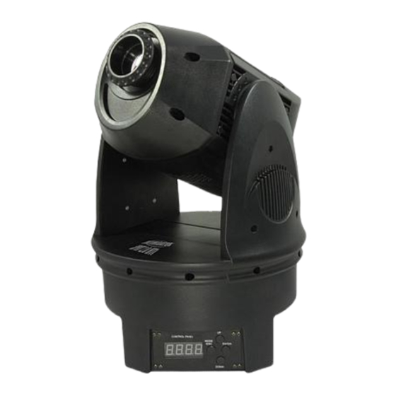
DMX-690
Intimidator Spot 2.0 HTI™
USER MANUAL
th
Chauvet, 3000 N 29
Ct, Hollywood, FL 33020 U.S.A.
(800) 762-1084 – (954) 929-1115
FAX (954) 929-5560
www.chauvetlighting.com
Snapshot
Ok on Dimmer
Outdoor OK
Sound Activated
DMX512
Master/Slave
115V/230V Switch
Replaceable Fuse
User Serviceable
Duty Cycle
Advertisement
Table of Contents

Subscribe to Our Youtube Channel
Related Manuals for Chauvet DMX-690


Summary of Contents for Chauvet DMX-690
-
Page 1: User Manual
DMX-690 Intimidator Spot 2.0 HTI™ Chauvet, 3000 N 29 Snapshot Sound Activated 115V/230V Switch Replaceable Fuse User Serviceable USER MANUAL Ct, Hollywood, FL 33020 U.S.A. (800) 762-1084 – (954) 929-1115 FAX (954) 929-5560 www.chauvetlighting.com Ok on Dimmer Outdoor OK DMX512... -
Page 2: Table Of Contents
ABLE OF ONTENTS 1. BEFORE YOU BEGIN... 3 ... 3 HAT IS INCLUDED ... 3 NPACKING NSTRUCTIONS AC P ... 3 OWER ... 3 ONTACT ... 4 AFETY NSTRUCTIONS 2. INTRODUCTION ... 5 ... 5 EATURES DMX C ... 5 HANNEL UMMARY ... -
Page 3: Before You Begin
Earth Ground. Contact Us W o r l d W i d e General Information Technical Support World Wide Web Intimidator Spot 2.0 HTI Manual EGIN Chauvet Lighting 3000 North 29 Court Hollywood, FL 33020 voice: 954.929.1115 fax: 954.929.5560 toll free: 800.762.1084... -
Page 4: Safety Instructions
Caution! There are no user serviceable parts inside the unit. Do not open the housing or attempt any repairs yourself. In the unlikely event your unit may require service, please contact CHAUVET at: 954-929-1115. Intimidator Spot 2.0 HTI Manual 2007-01-24/09:36... -
Page 5: Introduction
2. I NTRODUCTION Features • to 8-channel DMX-512 moving yoke • Pan: 540° / tilt: 270° • Variable strobe/shutter • Color wheel: 7 colors + white Rainbow color spin effect • Rotating gobo wheel: 7 interchangeable, rotating gobos + open 5 metal, 2 dichroic gobos Gobo wheel spin effect •... -
Page 6: Product Overview
Product Overview Head Yoke Base Rear of Base AC Power Input & Fuse Holder Intimidator Spot 2.0 HTI Manual Focusing Lens Control Panel Easy Controller Connector DMX Input Connector Voltage Selector Switch DMX Output Connector 2007-01-24/09:36... -
Page 7: Setup
3. S ETUP Lamp You will need to install a lamp prior to the initial operation of the fixture. A 150W HTI lamp is included. Warning! When replacing the lamp, please wait 15 minutes after powering down to allow the unit to cool down! Always disconnect from main power prior to lamp replacement. -
Page 8: Lamp Alignment How-To
Lamp Alignment How-To Often, after a new installation of a lamp, you will find that there is an uneven field of light or what is refered to as a hot spot. This is due to the most intense point of the lamp source not being positioned optimally within the reflector. -
Page 9: Replacing Gobos
Replacing Gobos Remove the four screws indicated in figure A to remove the back of the head. Remove the four screws indicated in figure B to remove the front of the head. Orient the fixture so that it looks like the fixture in figure C. -
Page 10: Fixture Linking
Maximum recommended number of fixtures on a serial data link: 32 fixtures Data Cabling To link fixtures together you must obtain data cables. You can purchase CHAUVET-certified DMX cables directly from a dealer/distributor or construct your own cable. If you choose to create your own cable please use data-grade cables that can carry a high quality signal and are less prone to electromagnetic interference. -
Page 11: 3-Pin To 5-Pin Conversion Chart
3-PIN TO 5- PIN CON VER SION CHAR T Note! If you use a controller wi pin to 3 pin adapter. CHAUVET Model No: DMX5M, or DMX5F. The chart below details a proper cable conversion: IN TO ONVERSION Ground/Shield Data ( - ) signal... -
Page 12: Mounting
Mounting ORIENTATION This fixture may be mounted in any position provided there is adequate room for ventilation. R IG G IN G It is important never to obstruct the fan or vents pathway. Mount the fixture using, a suitable “C” or “O” type clamp. Adjust the angle of the fixture by loosening both knobs and tilting the fixture. -
Page 13: Operating Instructions
4. O PERATING Navigating the Control Panel Access control panel functions using the four panel buttons located directly underneath the LCD Display. NOTE: The display will turn off after 30 seconds if no buttons are pushed. Button Used to access the menu or to scroll <MODE/ESC>... -
Page 14: Menu Map
Menu Map Intimidator Spot 2.0 HTI Manual 2007-01-24/09:36... -
Page 15: Menu Functions
Menu Functions PTION ESCRIPTION DMX: The fixture will be controlled by a DMX signal coming from a DMX controller. The starting address must be selected, and can be set using the up and down buttons. Automatic – Master Unit: Sets the fixture to Master status for Master-Slave operation and the built in programs will be triggered automatically. -
Page 16: To Change The Pan Range
TO CHANGE TH E PAN RANGE: Press <MODE/ESC> until Use the <UP> and <DOWN> buttons to scroll through the three options. Note: These settings only apply if the fixture is in master/slave or stand-alone modes. These settings will not affect a fixture operating in DMX mode. TO CHANGE TH E TILT RA NGE : Press <MODE/ESC>... -
Page 17: Operation
Operation Stand-Alone Mode (Sound-Active, Auto Mode, Easy Controller): This mode allows a single unit to run to the beat of the music, or the unit will auto change in Auto Mode. Press <MODE/ESC> until Use the <UP> and <DOWN> buttons to scroll through until the desired mode is displayed and press the <ENTER>... -
Page 18: Dmx Mode
DMX Mode This mode allows the unit to be controlled by any universal DMX controller. If you are unfamiliar with DMX, please read the DMX Primer on page 21. Press <MODE/ESC> until Use the <UP> and <DOWN> buttons to select the desired address and press the <ENTER> button. -
Page 19: Dmx Channel Values (8-Bit Mode)
DMX Channel Values (8-bit mode) HANNEL ALUE *Boomerang gobo rotation automatically rotates the gobo in one direction, and then automatically rotates it in the opposite direction an equal number of times. Intimidator Spot 2.0 HTI Manual UNCTION 0 – 540 (128 = halfway point) Tilt 0 –... -
Page 20: General Troubleshooting
If you still have a problem after trying the above solutions, please contact CHAUVET Technical Support at the location on the next page. Intimidator Spot 2.0 HTI Manual... -
Page 21: Technical Support
XLR male to female connectors. The shield connection is pin 1, while pin 2 is Data Negative (S-) and pin 3 is Data positive (S+). CHAUVET carries 3-pin XLR DMX compliant cables, DMX-10 (33’), DMX-4.5 (15’) and DMX-1.5 (5’) General Maintenance To maintain optimum performance and minimize wear fixtures should be cleaned frequently. -
Page 22: Returns Procedure
Package must be clearly labeled with a Return Merchandise Authorization Number (RA #). Products returned without an RA # will be refused. Call CHAUVET and request RA # prior to shipping the fixture. Be prepared to provide the model number, serial number and a brief description of the cause for the return. -
Page 23: Technical Specifications
Data output ... locking 3-pin XLR female socket Data pin configuration ...pin 1 shield, pin 2 (-), pin 3 (+) Protocols... DMX-512 USITT DMX Channels ...6-8 ORDERING INFORMATION Intimidator Spot 2.0 HTI ...DMX-690 WARRANTY INFORMATION Warranty ... 2-year limited warranty Intimidator Spot 2.0 HTI Manual 2007-01-24/09:36...
Need help?
Do you have a question about the DMX-690 and is the answer not in the manual?
Questions and answers