Table of Contents
Advertisement
Quick Links
Advertisement
Table of Contents

Related Manuals for DMP Electronics PC0128


Summary of Contents for DMP Electronics PC0128
- Page 1 Inst alla tIon GuIde Xt serIes™ Panels...
- Page 2 MODEL XT30/XT50 XT SERIES™ INSTALLATION GUIDE FCC NOTICE This equipment has been tested and found to comply with the limits for a Class B digital device, pursuant to part 15 of the FCC Rules. These limits are designed to provide reasonable protection against harmful interference in a residential installation.
-
Page 3: Table Of Contents
T able of ConTenTs Panel Specifications Power Supply .........1 Communication ........1 Panel Zones ..........1 Keypads/Expansion .........1 Number of Zones ........1 Outputs ..........1 1.7 Enclosure Specifications ......1 Introduction 2.1 System Configurations ......2 Caution Notes .........2 Compliance Instructions ......2 System Components 3.1 Wiring Diagram ........2 3.2 Lightning Protection ........2 3.3... - Page 4 T able of ConTenTs Powered Zone for 2-Wire Smoke Detectors 11.1 Terminals 25 and 26 ......12 Annunciator Outputs 12.1 Description ...........12 12.2 Harness Wiring ........12 12.3 Model 860 Relay Module ......12 Telephone RJ Connector 13.1 Description ...........13 13.2 FCC Registration ........13 13.3 Notification ...........13 Ethernet Connector J1 14.1...
- Page 5 T able of ConTenTs Central Station Burglar Alarm Units ANSI/UL 1610 23.1 Central Station ........18 23.2 Remote Disarm ........18 23.3 Central Station ........18 Household Fire Warning System ANSI/UL 985 NFPA 72 Specifications 24.1 Bell Output Definition ......18 24.2 Household System ........18 24.3 Household Fire Warning ......18 24.4 Wireless Supervision Time .....18 24.5...
-
Page 6: Panel Specifications
Panel sPecifica tions Panel Specifications Power Supply Transformer Input: Plug-in — 16.5 VAC 40 VA, Model 321 Wire-in — 16.5 VAC 40 VA, Model 320 Standby Battery: 12 VDC, 1.0 Amps Max. charging current Models 364, 365, 366, 368, or 369 Replace every 3 to 5 years Auxiliary Output: 12 VDC at 500mA 12 VDC at 325mA when used with two Model 364 batteries in the Model 341 enclosure Bell Output: 12 VDC at 1.5 Amps Smoke Detector Output: 12 VDC at 100mA All circuits inherent power limited Note: Please see the Listed Compliance Specifications section for certificated application requirements. Communication Built-in SDLC Digital Dialer communication to DMP Model SCS-1R Receivers Built-in network communication to DMP Model SCS-1R or SCS-VR Receivers Built-in or modular cellular communication to DMP Model SCS-1R or SCS-VR Receivers Built-in CID (Contact ID) dialer communication to DMP Model SCS-1R Receivers Panel Zones Nine 1k Ohm EOL burglary zones: zones 1 to 9 One 3.3k Ohm EOL Class B powered fire zone with reset capability: zone 10 Keypads/Expansion Connect up to eight supervised alphanumeric keypads. Connect up to four alphanumeric 9000 Series wireless keypads. Eight keypads total per panel. Connect additional unsupervised keypads. -
Page 7: Introduction
IntroductIon Introduction System Configurations The panel can be programmed to operate as any of the following system types: • All/Perimeter system that provides one perimeter area and one interior area • Home/Sleep/Away system that provides one perimeter, one interior, and one bedroom area. The bedroom area provides for any protection devices the user wants disarmed during their sleeping hours and armed in the Away mode. • Six area system that provides areas of protection that can be independently armed or disarmed. -
Page 8: Accessory Devices
system components Accessory Devices Cellular Communicator Cards 263G Digital Cellular Allows you to connect the XT30/XT50 Series to any compatible GPRS/SMS network and use Communicator Card its communication in place of standard dial out lines. 263C CDMA Cellular Communicator Allows you to connect the XT30/XT50 Series to any compatible CDMA/SMS network. Card 263H HSPA + Cellular Allows you to connect the XT30/XT50 Series to any compatible HSPA+/SMS network. Communicator Card The 263H is compatible with XT30 and XT50 Series control panels, version 112 or higher Zone and Output Expansion Modules 710 Bus Splitter/Repeater Increases keypad wiring distance to 2500 feet. 711 Single Point Zone Expander Provides one Class B zone for burglary devices and non-powered fire devices. 714, 714-8, 714-16 Zone Expander Provides Class B zones for burglary and non-powered fire devices. 712-8 Zone Expander Provides 8 zones for burglary devices. - Page 9 system components *1145-4 (Four-Button) Key Fob transmitters designed to clip onto a key ring or lanyard. *1145-2 (Two-Button) *1145-1 (One-Button) 1161 Residential Smoke Detector Residential smoke detector with sounder. 1162 Residential Smoke Detector Residential smoke/heat detector with sounder and fixed rate-of-rise heat detector 1183-135F Heat Detector Fixed temperature heat detector 1183-135R Heat Detector Fixed temperature and rate-of-rise heat detector 1184 Carbon Monoxide Detector Carbon Monoxide Detector. Keypads *ePAD™ Mobile Keypad Allows users to control the security system from any computer using the Internet. LCD keypads Allows you to control the panel from various remote locations. Connect up to eight keypads.
-
Page 10: Xt30/Xt50 Wiring Diagram
Inst alla tIon XT30/XT50 Wiring Diagram HOUSEHOLD FIRE WIRING NFPA 72 USE MARKING This equipment should be installed in accordance with Chapter 11 Recognized limited energy cable must be Commercial Central Station; Household Fire and of the National Fire Alarm Code, ANSI/NFPA 72-2002, (National used for connection of all initiating, Burglar Warning System Control Unit (DACT, Fire Protection Association, Batterymarch Park, Quincy, MA... -
Page 11: Installation
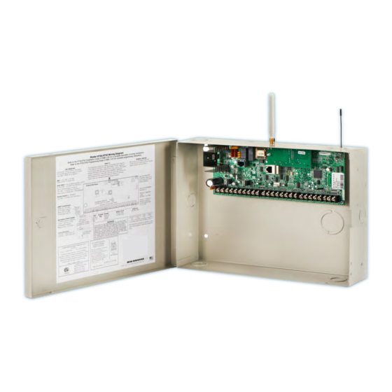
Inst alla tIon Installation Mounting the Enclosure The metal enclosure must be mounted in a secure, dry place to protect the panel from damage due to tampering or the elements. It is not necessary to remove the PCB when installing the enclosure. The PCB may be installed in the standard 340 Small enclosure, optional 341 Kiosk enclosure, optional 349 Medium enclosure, or the optional 349A Attack enclosure. -
Page 12: Mounting Keypads
Inst alla tIon Mounting Keypads DMP keypads have removable covers that allow the base to be mounted on a wall or other flat surface using the screw holes provided on each corner. For mounting keypads on solid walls, or for applications where conduit is required, use a DMP 695 or 696 keypad conduit backbox. Installation Specifications Several factors determine the performance characteristics of the keypad bus: the length of wire used, the number of devices connected, and the voltage at each device. When planning a keypad bus installation, keep in mind the following four specifications: 1. DMP recommends using 18 or 22-gauge unshielded wire for all keypad circuits. Do not use twisted pair or shielded wire for keypad bus data circuits. 2. On keypad bus circuits, to maintain auxiliary power integrity when using 22-gauge wire do not exceed 500 feet. When using 18-gauge wire do not exceed 1,000 feet. To increase the wire length or to add devices, install an additional power supply. Note: Each panel allows a specific number of supervised keypads. Add additional keypads in the unsupervised mode. Refer to the panel installation guide for the specific number of supervised keypads allowed. 3. Maximum distance for any one bus circuit (length of wire) is 2,500 feet regardless of the wire gauge. This distance can be in the form of one long wire run or multiple branches with all wiring totaling no more than 2,500 feet. As wire distance from the panel increases, DC voltage on the wire decreases. -
Page 13: Secondary Power Supply
Inst alla tIon Secondary Power Supply Battery Terminals 3 and 4 XT30/XT50 Connect the black battery lead to the Command Processor negative battery terminal. The negative Panel terminal connects to the enclosure –B BELL GND ground internally through the XT30 or To AC XT50 circuit board. Connect the red Panel Red and battery lead to the positive battery Black Battery Cables terminal. Observe polarity when... -
Page 14: Xt30/Xt50 Standby Battery Calculations
Inst alla tIon XT30/XT50 Standby Battery Calculations Standby Battery Power Calculations Alarm Current XT30 Panel 125mA ______mA 125mA ______mA XT50 Panel 145mA ______ 145mA ______ Built-in Network (additional current) 145mA ______ 145mA ______ Built-in Cellular (additional current) 18mA ______ 18mA ______ Active Zones 1-9 1.6mA... -
Page 15: Bell Output
Inst alla tIon Bell Output Terminals 5 and 6 Nominal 12 VDC is supplied by terminal 5 on the panel to power alarm bells or horns. The output is rated for a maximum of 1.5 Amps with a 40 VA transformer. This output can be steady, pulsed, or Temporal Code 3 depending upon the Bell Action specified in Output Options programming. Terminal 6 is the ground reference for the bell circuit. If using a horn or siren, a 1k 0hm resister should be added across the bell circuit for supervision. Keypad Data Bus Description Terminals 7, 8, 9, and 10 of the panel are designated as the keypad data bus. In addition to keypads, the XT30/XT50 allows the connection of any combination of zone expansion modules, Glassbreak Detectors, and PIRs to the keypad bus up to the maximum of eight devices. Terminal 7 - RED Nominal 12 VDC is supplied at terminal 7 to power keypads and zone expanders. This is also where power for any auxiliary device is supplied. The ground reference for terminal 7 is terminal 10. The maximum output is rated at 500mA. All auxiliary devices totaled together must not exceed the Terminal 7 maximum current rating of 500mA. When the number of keypads or other expansion devices attached exceeds the amount of output current available, attach an external power supply as defined in the Model 710 Installation Sheet (LT-0310). Terminal 8 - YELLOW Data receive from keypads and zone expanders. Terminal 9 - GREEN Data transmit to keypads and zone expanders. -
Page 16: Overcurrent Ovc Led
Inst alla tIon Overcurrent OVC LED The Overcurrent LED (OVC) lights Red when the devices connected to the Keypad Bus draw more current than the auxiliary output rating. The OVC LED is located above terminals 9 and 10 as shown in Figure 4. When the OVC LED J7 RJ Supervision lights Red, the Keypad bus/auxiliary power (terminal 7) and the Programming header (J8) shut down. Phone Line Smoke and Glassbreak Detector Output OVC LED Power Terminal 11 Nominal 12 VDC at 100mA maximum (shared by terminal 25) is supplied at terminal 11 to power 4-wire smoke detectors or other auxiliary powered devices. This output can be turned off by the user for 5 seconds using the Sensor Reset option Figure 5: OVC LED location in the User Menu. Terminal 10 is the ground reference for terminal 11. -
Page 17: 10.3 Zone Response Time
Inst alla tIon 10.3 Zone Response Time A condition must be present on a zone for 500 milliseconds before it is detected by the panel. Ensure detection devices used on the protec t ion zones are rated for use with this delay. 10.4 Keyswitch Arming Zone You can use a momentary keyswitch on a zone programmed as an Arming type for use in arming and disarming the system without a code. Powered Zone for 2-Wire Smoke Detectors 11.1 Terminals 25 and 26 A resettable 2-wire Class B powered zone is provided on terminals 25 (positive) and 26 (negative) of the panel. For programming purposes, the zone number is 10 on the XT30/XT50. The zone uses a Model 309, 3.3k Ohm EOL resistor (provided with the panel) and has an operating range of 8.8 to 13.9 VDC. The compatibility identifier is: B Caution: Sensor reset on zone 10 drops power to devices on this zone, causing the panel to sense an open condition on all zone types other than Fire, Fire Verify, and Supervisory. Whenever non-Fire and non- Supervisory zone types are used on zone 10, make the appropriate adjustments to the zone’s Armed Action to prevent false alarms from occurring. - Page 18 Inst alla tIon Telephone RJ Connector 13.1 Description Connect the panel to the public telephone network by installing a DMP 356 RJ Cable between the panel’s J3 connector and the RJ31X or RJ38X phone jack. CAUTION - To reduce the risk of fire, use only No. 26 AWG or larger telecommunication line cord, such as DMP Model 356 Series Phone Cords. A two pin header labeled RJ SUP (J7) is provided to allow monitoring of the telephone cable connected between the panel and a RJ38X jack (pins 2 and 7 jumpered). Attach a DMP Model 306 Harness between J7 and any available zone. The J7 pins are connected via the telephone cable to the RJ38X jack pins 2 and 7. The RJ38X jack provides a jumper between pins 2 and 7 which completes the circuit. Program the zone as a Supervisory type (SV). When the telephone cable is removed, the keypad displays zone trouble and produces a steady tone. To Telephone Line Ring RJ31X or RJ38X Phone Block Ring 1 Tip 1 To Premise Phone(s) Figure 7: Phone Jack Wiring 13.2 FCC Registration The panel complies with FCC part 68 and is registered with the FCC.
- Page 19 Inst alla tIon Reset Header J16 15.1 Description The reset header is located just above the terminal strip on the right side of the circuit board and is used to reset the XT30/XT50 microprocessor. To reset the panel when first installing the system, install the reset jumper before applying power to the panel. After connecting the AC and battery, remove the reset jumper. To reset the panel while the system is operational, for example, prior to reprogramming, install the reset jumper without powering down the system. Remove the reset jumper after one or two seconds. After resetting the panel, begin programming within 30 minutes. If you wait longer than 30 minutes, reset the panel again. XT30/XT50 Panel Wireless Antenna J24 Celllular connection header TX RX Wireless LEDs...
- Page 20 Inst alla tIon Flash Load Jumper J18 16.1 Description The XT Series panel software can be updated via the panel’s programming (PROG) header. To update the panel with a new software version, complete the following steps at the protected premise: 1. Place a jumper across the Reset (J16) header and then remove the yellow and green wires from keypad bus terminals 8 and 9. 2. Connect a DMP 399 Cable from the J8 Programming Header to the serial port of your PC operating Remote Link and containing the XT RU file. Requires Remote Link 1.43 or higher. 3. Start Remote Link and create or open the XT Series control panel account that matches the panel to be updated. 4. Set the Connection Information Type to Direct with a baud rate of 38400 and choose the appropriate COM port. 5. Select Panel>Remote Update, then select the correct RU file for the XT panel model. 6. While placing a short across the LOAD (J18) header, remove the jumper from the Reset (J16) header. Click <Update> in Remote Link. 7. After the software version is updated, remove the short from the LOAD header. Place the jumper across Reset (J16) then remove the 399 cable. 8. Replace the yellow and green wires to terminals 8 and 9. 9. Remove Reset (J16) jumper to resume normal panel operation. Cellular Connections 17.1 Cellular The J24 header is provided to connect a 263G Digital Cellular Communicator, 263C CDMA Cellular Communicator, or 263H HSPA+ Cellular Communicator. The cellular antenna connection protrudes through the top of the enclosure.
- Page 21 COMPLIANCE On-Board 1100 Series Wireless Antenna Connection 18.1 Wireless Antenna The XT50 Wireless Antenna terminal block J20 is located at the top right corner of the circuit board. The antenna installs through a small opening in the top of the enclosure and is attached to the panel using the right terminal. The left terminal is not used. The XT50 built-in wireless operates with DMP 1100 Series transmitters. See section 3.4 for a list of accessory devices.
- Page 22 COMPLIANCE Listed Compliance Specifications 20.1 Introduction The programming and installation specifications contained in this section must be completed when installing the XT30/XT50 in accordance with any of the ANSI/UL burglary standards. Additional specifications may be required by a particular standard. 20.2 Bypass Reports The bypass reports must be programmed as YES for all listed burglary applications. 20.3 Current Draw The total current draw from a combination of auxiliary, smoke, and bell output terminals must not exceed 1.6 Amps. 20.4 Battery Standby Use battery Models 365 (12 VDC 9Ah) or 366 (12 VDC 18Ah) with the XT30/XT50 panel when installed in the 340, 341, 349, or 349A enclosures. The Model 364 (12 VDC 1.3Ah) battery is for use with the XT30/XT50 panel when using the 341 enclosure with the optional 341B Battery Bracket. The Model 364 battery is rated for 4 hours of standby time. 20.5 Auxiliary and Bell Current For UL listed applications, the maximum auxiliary current is 400mA, and the maximum bell current is 500mA. 20.6 Cross Zoning Each zone must have the capability of protecting the common area individually. 20.7 Software Version For UL listed applications, the minimum software version must be Version 103.
- Page 23 COMPLIANCE Central Station Burglar Alarm Units ANSI/UL 1610 23.1 Central Station Digital Dialer Central Station (DACT) service for commercial application can be provided by adding a listed local audible signal appliance and placing the XT30 or XT50 panel into the Model 349A Attack Resistant Enclosure. 23.2 Remote Disarm REMOTE DISARM must be programmed as NO. 23.3 Central Station MESSAGE TO TRANSMIT programming for zones must not be set to LOCAL (L). Household Fire Warning System ANSI/UL 985 NFPA 72 Specifications 24.1 Bell Output Definition The bell output of the Model XT30/XT50 must be programmed to operate steady on burglary alarms and temporal on fire alarms. See the XT30/XT50 Programming Guide. 24.2 Household System An alarm sounding device must be installed indoors so that it is clearly heard in all sleeping areas.
- Page 24 COMPLIANCE False Alarm Reduction Programmable Options ANSI/SIA CP-01-2010 26.1 Shipping Defaults and Recommended Programming SIA CP-01 FEATURE DMP PROGRAMMING SHIPPING RECOMMENDED PARAGRAPH # AND GUIDE LT-0981 REQUIREMENT RANGE DEFAULT PROGRAMMING* DESCRIPTION SECTION # Required 4.2.2.1 Exit Time 8.6 Exit Delay 45 sec. - 250 sec. 60 Seconds (Programmable) Seconds Individual keypads 4.2.2.2 Progress...
- Page 25 COMPLIANCE 26.2 Call Waiting The Call Waiting default setting is disabled. To cancel the Call Waiting feature, program * (star) 7 0 P (pause), the standard telephone code prefix that cancels call waiting, into the telephone number string. Cancel Call Waiting for telephone lines that have Call Waiting operational on the telephone line. See the XT30/XT50 Programming Guide. Caution: A call waiting cancel programmed on a non-call waiting telephone line, would prevent communication to the central station. 26.3 Entry Delay Only use Entry Delay 1. Do not use Entry Delay 2. See the XT30/XT50 Programming Guide. 26.4 Local Bell All non-fire zones such as Night, Day, Exit, Aux1 and Aux 2 must be programmed for local bell enabled with a bell cutoff time set to a minimum of 6 minutes to provide a cancel window of 5 minutes or greater. This does not apply to manually operated zone types such as Panic and Emergency.
- Page 26 COMPLIANCE Troubleshooting 27.1 Troubleshooting Section This section provides troubleshooting information for use when installing or servicing an XT30/XT50 system. Problem Possible Cause Possible Solutions J16 Jumper is installed. Remove the J16 reset jumper. Open or short on the green data wire to Check for broken or shorted wires between Keypad displays “SYSTEM TROUBLE” the keypad. the panel and the keypad. Bad keypad or zone expander is affecting Replace keypad or zone expander. the Green data wire. Open or short on the yellow data wire to Check for broken or shorted wires between Keypad keyboard is not functional. the keypad. the panel and the keypad. When a key is pressed, only a short Bad keypad or zone expander. is affecting beep is emitted. Replace keypad or zone expander.
- Page 27 TroubleshooTing Wiring Diagrams 28.1 Multiple Indicating Circuit Modules Installation Digital Monitoring Products XT30/XT50 Installation Guide...
- Page 28 Wiring Diagrams 28.2 System Sensor 2-Wire Smoke Detectors XT30/XT50 Panel TX RX Wireless LEDs J7 RJ Supervision Outputs Ethernet Phone Line OVC LED Power Reset XMIT Programming to transformer PWR + 2W-MOD2 PWR - SYSTEM SENSOR LOOP OUT + TEST & MAINTENANCE MODULE OUT - IN + IN -...
- Page 29 Revisions Revisions to This Document This section explains the changes that were made to this document during this revision. This section lists the version, section number with heading, and a quick summary of the change. Ver. Section Number and Heading Summary of Changes 1.14 3.3 Accessory Devices Removed 1126W 6.7 Standby Battery Calculations Added 860 to table 17.1 Cellular Updated cellular options Listings and Approvals Updated FCC, removed UL 1.13 1.7 Enclosure Specifications...
- Page 30 Digital Monitoring Products XT30/XT50 Installation Guide...
- Page 31 FCC Part 15 ID: CCKPC0128 FCC Part 68 Registration ID CCKAL00BXT50 Industry Canada ID: 5251A-PC0128 8 0 0 - 6 4 1 - 4 2 8 2 I n t r u s I o n • f I r e • A c c e s s • n e t w o r k s w w w .
Need help?
Do you have a question about the PC0128 and is the answer not in the manual?
Questions and answers