Advertisement
Quick Links
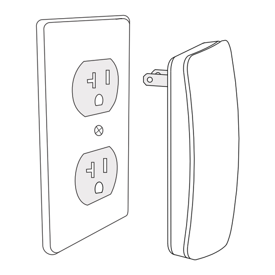
1136 WIRELESS REMOTE CHIME
Installation Guide
Figure 1: 1136
DESCRIPTION
The 1136 Wireless Remote Chime is
a multi-function sounder that plugs
directly into a standard 110 VAC wall
outlet.
The 1136 provides extra
annunciation in installations that
benefit from a louder keypad chime,
or small applications where no
keypad is installed and the system
is controlled from an app.
The 1136 annunciates Chimes (Zone
Monitor), as well as Entry Delay, Exit
Delay and Alarm messages.
What is Included?
•
1136 Wireless Remote Chime
1
PROGRAM THE PANEL
The 1136 is programmed in the panel as a wireless output. Refer to
the panel programming guide as needed.
If a wireless keypad is used, the 1136 will follow the first wireless
keypad that was added and sound with the keypad. If a hardwired
keypad is used, the 1136 will follow the first hardwired device on the
system and sound with the keypad.
For panels with Version 171 firmware or below, there must be a
wireless keypad installed on-site and programmed into the system
for the 1136 to sound with the keypad.
1.
In OUTPUT INFO (XR Series and XT75 Control Panels) or
OUTPUT SETUP (XTL Series and XT30/XT50 Control Panels),
enter the OUTPUT number. For the first 1136 added to a
system, use the following output numbers:
Panel
XT Series
XTL Series
XT75
XR Series
2.
Enter the OUTPUT NAME.
Enter the eight-digit SERIAL# and press CMD.
3.
Enter the SUPRVSN TIME (Supervision Time) and press CMD.
4.
5.
Select NO when TRIP WITH PANEL BELL displays. Selecting
NO will allow the device to listen for keypad messages to
sound instead of bell options.
6.
Press the back arrow when OUTPUT SETUP displays.
7.
For XR systems that need to send trouble notifications about
the Chime, see Additional Programming below.
Press CMD until STOP displays and then press any top row
8.
select key or area to save and exit programming.
2
SELECT A LOCATION
The 1100 Wireless Series provides a Survey LED capability on most
transmitters to allow one person to confirm communication with the
wireless receiver or panel while the cover is removed.
This device does not have the Survey LED functionality so use
either an 1101 Universal Transmitter or 1106 Universal Transmitter to
perform the following test to select a good location for the 1136.
1.
With the cover removed, hold the transmitter in the exact
desired location.
2.
Press the tamper switch to send data to the panel and
determine if communication is confirmed or faulty.
Confirmed: If communication is confirmed, for each press
or release of the tamper switch, the LED blinks
immediately on and immediately off. Repeat this test to
confirm five separate consecutive LED blinks. Any
indication otherwise means proper communication has
not been established.
Faulty: If communication is faulty, the LED remains on for
about 8 seconds or flashes multiple times in quick
succession. Relocate the transmitter until the LED
confirms clear communication.
Note: If the DMP-recommended survey tests cannot be
followed, see Test the 1136 below for more details.
First Output
Additional Output
Number
Numbers
34
31-33 and 41-44
54
51-53 and 61-64
453
450-452, 454-474, and 480-499
453
450-452, 454-474, and 480-499
Advertisement

Subscribe to Our Youtube Channel
Related Manuals for DMP Electronics XT75


Summary of Contents for DMP Electronics XT75
- Page 1 For panels with Version 171 firmware or below, there must be a wireless keypad installed on-site and programmed into the system for the 1136 to sound with the keypad. In OUTPUT INFO (XR Series and XT75 Control Panels) or Figure 1: 1136 OUTPUT SETUP (XTL Series and XT30/XT50 Control Panels), enter the OUTPUT number.
- Page 2 PLUG IN THE 1136 Use an outlet where the 1136 has good communication to the panel based on the results of the LED survey. Caution: To reduce the risk of electric shock, do not remove or open the 1136’s cover. TEST THE 1136 After the 1136 has been programmed and plugged in to an outlet, test the 1136 to confirm that it is communicating clearly with the panel.
Need help?
Do you have a question about the XT75 and is the answer not in the manual?
Questions and answers