DMP Electronics XT30 Installation Manual
Hide thumbs
Also See for XT30:
- User manual (72 pages) ,
- Installation manual (30 pages) ,
- Programming manual (48 pages)
Table of Contents
Advertisement
Quick Links
Advertisement
Table of Contents

Related Manuals for DMP Electronics XT30


Summary of Contents for DMP Electronics XT30
- Page 1 Inst alla tIon GuIde Xt serIes™ Panels...
- Page 2 MODEL XT30/XT50 XT SERIES™ INSTALLATION GUIDE FCC NOTICE This equipment has been tested and found to comply with the limits for a Class B digital device, pursuant to part 15 of the FCC Rules. These limits are designed to provide reasonable protection against harmful interference in a residential installation.
-
Page 3: Table Of Contents
Earth Ground ..........7 Replacement Period ........7 6.4 Discharge/Recharge ........7 Battery Supervision .........7 XT30/XT50 Power Requirements ....7 XT30/XT50 Standby Battery Calculations ..8 Bell Output Terminals 5 and 6 ........9 Keypad Data Bus Description ..........9 Terminal 7 - RED........9 Terminal 8 - YELLOW ......9 Terminal 9 - GREEN.........9... - Page 4 Central Station ........16 Household Fire Warning System ANSI/UL 985 NFPA 72 Specifications 22.1 Bell Output Definition ......17 22.2 Household System ........17 22.3 Household Fire Warning ......17 22.4 Wireless External Contact ......17 22.5 Wireless Supervision Time .....17 22.6 Wireless Fire Verification ......17 Digital Monitoring Products XT30/XT50 Installation Guide...
- Page 5 Shipping Defaults and Programming ..18 24.2 Call Waiting ..........19 24.3 Entry Delay ..........19 24.4 Local Bell ..........19 24.5 Minimum Installation Requirements ..19 Troubleshooting 25.1 Troubleshooting Section ......20 25.2 Common LCD Keypad Displays ....20 Wiring Diagrams 26.1 Multiple Indicating Circuit Modules ..21 Listings and Approvals ........22 Digital Monitoring Products XT30/XT50 Installation Guide...
-
Page 6: Panel Specifications
Five keypad bus addresses with zones 11-14, 21-24, 31-34, 41-44, and 51-54 (hardwired or wireless) • Zone numbers 31 to 34 and 41 to 44 can support 1100 Series Key Fobs or DMP wireless output modules • XT50 has 20 additional onboard wireless zones numbered 80-99 Outputs The XT30/XT50 panels provide four open collector outputs rated for 50mA each. A Model 300 Output Harness is required. The open collector outputs provide the ground connection for a positive voltage source. Enclosure Specifications The XT30/XT50 panel ships standard in a 340 enclosure with EOL resistors, battery leads, user’s guide, and programming sheet. All enclosures are constructed using 20-gauge cold rolled steel. Enclosure Size Color Model 12.5” W x 9.5” H x 2.75” D Gray (G) 12.5” W x 11.25” H x 3.5” D Gray (G) Digital Monitoring Products XT30/XT50 Installation Guide... -
Page 7: Introduction
Remove All Power From the Panel! Remove all AC and Battery power from the panel before installing or connecting any modules, cards, or wires to the panel. NRTL Compliance Instructions For applications that must conform to a local authorities installation standard or a NRTL (National Recognized Testing Laboratory) certificated system, please see the NRTL Listed Specifications section near the end of this guide for additional instructions. Digital Monitoring Products XT30/XT50 Installation Guide... -
Page 8: System Components
Provides concealed protection for doors, windows or other applications needing a discreet contact. 1139 Bill Trap Provides a silent alarm option for retail and banking cash drawers. 1142BC Two-button Panic Belt Provides portable two-button panic operation. Clip Transmitter 1142 Two-button Panic Provides permanently mounted under-the-counter two-button panic operation. Transmitter 1145 (Four-Button) Key Fob transmitters designed to clip onto a key ring or lanyard. 1146 (Two-Button) 1147 (One-Button) Digital Monitoring Products XT30/XT50 Installation Guide... -
Page 9: Accessory Devices Continued
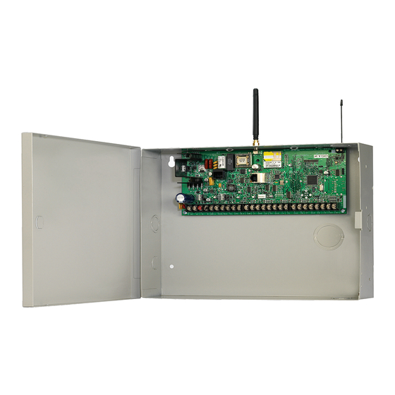
Class 2. Household Burglary. Test weekly. SIA CP-01-2007 minimum system is J19 Celllular XT30/XT50 Wireless XT30 or XT50, local Bell, and off premise Antenna Antenna Command Processorô Panel connection DACT communication to an AC Wiring must be in conduit and exit out connection the left side of the enclosure. -
Page 10: Installation
This distance can be in the form of one long wire run or multiple branches with all wiring totaling no more than 2,500 feet. As wire distance from the panel increases, DC voltage on the wire decreases. 4. Maximum voltage drop between the panel (or auxiliary power supply) and any device is 2.0 VDC. If the voltage at any device is less than the required level, add an auxiliary power supply at the end of the circuit. When voltage is too low, the devices cannot operate properly. For additional information refer to the 710 Installation Sheet (LT-0310) and or the LX-Bus/Keypad Bus Wiring Application Note (LT-2031). Digital Monitoring Products XT30/XT50 Installation Guide... -
Page 11: Primary Power Supply
Proper grounding protects against Electrostatic Discharge (ESD) that can damage system components. See Earth ground, in the Secondary Power Supply section. Transformer Types The transformer for the panel is 16.5 VAC 40 VA, which provides up to 1.5 Amps of bell output current, 500mA of auxiliary current, and 100mA of smoke detector output. You can use either the Model 320 wire-in or 321 plug-in transformer with the panel. The total current available is limited by the total battery standby requirements of the installation. The transformer must be connected to a 120 VAC 60 Hz commercial power outlet that is not con t rolled by a wall switch. Never share the transformer output with any other equipment. Digital Monitoring Products XT30/XT50 Installation Guide... -
Page 12: Secondary Power Supply
Batteries Black Circuit supplied by DMP have been tested to ensure proper charging with DMP Battery products. Battery GEL CELL BATTERIES CANNOT BE USED WITH THE XT30/XT50 PANEL. Figure 4: Wiring Multiple Batteries Earth Ground Terminal 4 of the panel must be connected to earth ground using 14 gauge or larger wire to provide proper transient suppression. DMP recommends connecting to a metal cold water pipe or ground rod only. Do not connect to electrical conduit or a telephone company ground. Replacement Period DMP recommends replacing the battery every 3 to 5 years under normal use. Discharge/Recharge The panel battery charging circuit float charges at 13.9 VDC at a maximum current of 1.2 Amps using a 40 VA... -
Page 13: Xt30/Xt50 Standby Battery Calculations
Inst alla tIon XT30/XT50 Standby Battery Calculations Standby Battery Power Calculations Alarm Current XT30 Panel 125mA ______mA 125mA ______mA XT50 Panel 145mA ______ 145mA ______ Built-in Network (additional current) 145mA ______ 145mA ______ Built-in Cellular (additional current) 17mA ______ 65mA... -
Page 14: Bell Output
Programming Connection A locking 4-pin header (J8) is provided to connect a keypad when using a DMP Model 330 Programming Cable. This provides a quick and easy connection for programming the panel. Keypad Addressing Keypad Bus expansion zones are numbered in groups of four corresponding to the address. Example: address 1 is zones 11-14 and address 5 is zones 51-54. There are a maximum of 20 zones possible on the Keypad Bus. All keypad zones terminate with a 1k 0hm EOL resister. Address XT30/XT50 Zone Number 11-14 21-24 31-34 41-44 51-54 OVC LED The Overcurrent LED (OVC) lights Red when the devices connected to the Keypad Bus and LX-Bus(es) draw more current than the panel is rated for. The OVC is located above Outputs 1 and 2 on the panel and turns a steady Red when lit. When the OVC LED lights Red, the LX-Bus(es) and Keypad bus are shut down. Smoke and Glassbreak Detector Output Terminal 11 Nominal 12 VDC at 100mA maximum (shared by terminal 25) is supplied at terminal 11 to power 4-wire smoke detectors or other auxiliary powered devices. This output can be turned off by the user for 5 seconds using the Sensor Reset option in the User Menu. Terminal 10 is the ground reference for terminal 11. Digital Monitoring Products XT30/XT50 Installation Guide... -
Page 15: Burglary Zones
Normally Open Combination Normally Open Closed and Normally Closed Figure 5: Protection Zone Contact Wiring 10.3 Zone Response Time A condition must be present on a zone for 500 milliseconds before it is detected by the panel. Ensure detection devices used on the protec t ion zones are rated for use with this delay. 10.4 Keyswitch Arming Zone You can use a momentary keyswitch on a zone programmed as an Arming type for use in arming and disarming the system without a code. Digital Monitoring Products XT30/XT50 Installation Guide... -
Page 16: Terminals 25 And 26
715-16, 725 HSB-200, 715, 715-8, DMP/Hochiki SLK-835 HD-5 HB-55 HSB-200N 715-16 715, 715-8, DMP/Hochiki SLR-835 HD-3 NS6-100 HB-55 715-16, 725 715, 715-8, DMP/Hochiki SLR-835B HD-6 715-16, 725 715, 715-8, Sentrol/ESL 429AT, 521B, 521BXT S09A 715-16 Digital Monitoring Products XT30/XT50 Installation Guide... -
Page 17: Description
Green Yellow Black 12.3 Model 860 Relay Module Connect a Model 860 Relay Module to the panel to provide relays for the annunciator outputs that can be used for electrical isolation between the alarm panel and other systems or for switching voltage to control various functions. The module includes one relay and provides three additional sockets for expansion of up to four relays. Power is supplied to the relay coils from the panel keypad bus. The 860 mounts inside the panel enclosure using the 3-hole mounting configuration. Plastic standoffs are provided with the module for ease of installation. A 4-wire harness is also provided that connects the Model 860 to the panel. Relay Contact Rating: 1 Amp at 30 VDC Digital Monitoring Products XT30/XT50 Installation Guide... -
Page 18: Description
Registered terminal equipment must not be repaired by the user. In case of trouble, the device must be immediately unplugged from the telephone jack. The factory warranty provides for repairs. Registered terminal equipment may not be used on party lines or in connection with coin telephones. No t ification must be given to the telephone company with the following information: a. The particular line(s) the service is connected to b. The FCC registration number c. The ringer equivalence d. The make, model, and serial number of the device Digital Monitoring Products XT30/XT50 Installation Guide... -
Page 19: Description
Reset jumper over both Reset of the J16 pins to reset the panel. Programming Figure 9: Panel Showing the Reset Jumper Wires Flash Load Jumper J18 16.1 Description To update the XT30/50 panel with a new software version (ru file), place jumpers on the Reset (J16) and Load (J18) headers. Connect a DMP 399 Cable from the J8 Programming Header to a laptop PC containing the ru file. Then, remove the jumper from the Reset (J16) header while leaving the Load (J18) jumper in place. After the software version is updated, return the jumper to Reset (J16), remove the Load (J18) jumper and the 399 cable. Then remove Reset (J16) jumper to resume normal panel operation. Digital Monitoring Products XT30/XT50 Installation Guide... -
Page 20: Cellular
The left terminal is not used. The XT50 built-in wireless operates with DMP 1100 Series transmitters. See section 3.4 for a list of accessory devices. 18.2 LED Operation Two LEDs display receiver operation and activity. Refer to the table below as required. Operation Green LED - Flashes to indicate data is being transmitted from the receiver. Yellow LED - Flashes to indicate data is being received from a transmitter. Digital Monitoring Products XT30/XT50 Installation Guide... -
Page 21: Introduction
The maximum entry delay used must not be more than 60 seconds. 21.2 Exit Delay The maximum exit delay used must not be more than 60 seconds. 21.3 Test Frequency The Test Frequency option must be programmed to send a report once every 24 hours. 21.4 Automatic Bell Test This option must be programmed as YES. 21.5 Central Station Digital Dialer Central Station (DACT) service for commercial application can be provided under UL 1635 by adding a listed local audible signal appliance and placing the XT30 or XT50 panel into the Model 350A Attack Resistant Enclosure. Digital Monitoring Products XT30/XT50 Installation Guide... -
Page 22: California State Fire Marshal Specifications
22.3 Household Fire Warning Recognized limited energy cable must be used for connection of all initiating, indicating, and supplementary devices. 22.4 Wireless External Contact When used, the External Contact of 1101 or 1102 must be programmed Normally Closed. See the XT30/ XT50 Programming Guide. 22.5 Wireless Supervision Time The Zone Information Supervision Time must be 3 minutes for fire devices. See the XT30/XT50 Programming Guide. 22.6 Wireless Fire Verification When used, the Model 1161 and 1162 wireless smoke detectors must not be programmed as Fire Verification (FV) zone type. See the XT30/XT50 Programming Guide. California State Fire Marshal Specifications 23.1 Bell Output Definition The bell output of the Model XT30/XT50 must be programmed to operate steady on burglary alarms and temporal on fire alarms. Digital Monitoring Products XT30/XT50 Installation Guide... -
Page 23: False Alarm Reduction Programmable Options Ansi/Sia Cp-01-2007
1 trip 4.3.2 Swinger Shutdown For non-police 13.13 Swinger Bypass Allowed Enabled (all zones) Disable response zones Yes as required 4.3.3 Fire Alarm 13.5 Zone Type Required Option FV Type Zone (unless sensors can Verification self verify) 3.17 First Telephone Include *70P in Enabled if user has 4.5 Call Waiting Cancel Required Option Disabled Number Telephone Number call waiting * Programming at installation may be subordinate to other NRTL requirements for the intended application. ** For NRTL Installations, combined Entry Delay and Transmit Delay should not exceed 1 minute. Digital Monitoring Products XT30/XT50 Installation Guide... -
Page 24: Call Waiting
6 minutes to provide a cancel window of 5 minutes or greater. This does not apply to manually operated zone types such as Panic and Emergency. 24.5 Minimum Installation Requirements SIA CP-01-2007 minimum system installation requirements include an XT30 or XT50, a local Bell, and off premise DACT communication to an SCS-1R receiver plus one of the following compatible keypads. 690, 693, 790, 793 Security Command™ keypads 7060, 7063, 7070, 7073, 7160, 7163, 7170, or 7173 Thinline™ keypads 7060A, 7063A, 7070A, or 7073A Aqualite™ keypads 7360 or 7363 Thinline™ Icon keypads 7760 Clear Touch™ keypad Digital Monitoring Products XT30/XT50 Installation Guide... -
Page 25: Troubleshooting
BATTERY TROUBLE The battery is either low or missing. the battery is still good. Digital Monitoring Products XT30/XT50 Installation Guide Make sure the J16 jumper is removed from the panel. Make sure there is not a short or open SYSTEM TROUBLE or There is a problem with one or more components in... -
Page 26: Wiring Diagrams
WIrInG dIaGrams Wiring Diagrams 26.1 Multiple Indicating Circuit Modules Installation Digital Monitoring Products XT30/XT50 Installation Guide... -
Page 27: Listings And Approvals
Listings and Approvals California State Fire Marshal (CSFM) ETL: ANSI/SIA CP-01 False Alarm Reduction ANSI/UL 1023 Household Burglar ANSI/UL 985 Household Fire Warning ANSI/UL 1635 Digital Burglar FCC Part 15 ID: CCKPC0096 FCC Part 68 Registration ID CCKAL00BXT50 Industry Canada ID: 5251A-PC0096 800-641-4282 IN TRU SIO N • F IRE • AC C ESS • NET WOR KS www.dmp.com 2500 North Partnership Boulevard Made in the USA Springfield, Missouri 65803-8877...
Need help?
Do you have a question about the XT30 and is the answer not in the manual?
Questions and answers