
Related Manuals for National Semiconductor INA260


Summary of Contents for National Semiconductor INA260
- Page 1 INA260EVM-PDK INA260 Evaluation Module and Product Demonstration Kit User's Guide Literature Number: SBOU180 November 2016...
-
Page 2: Table Of Contents
Contents ..........................Overview ..................... INA260EVM-PDK Contents ..................... INA260EVM-PDK Features ..............Related Documentation from Texas Instruments ....................INA260EVM-PDK Hardware ..................SM-USB-DIG Platform Description ..................INA260EVM PCB Description ..................EVM Digital Inputs and Outputs ....................... INA260EVM-PDK Setup ................. One-Time GUI Software Installation .................. - Page 3 ..................... Slave Address Setting ..................... Operating Mode Menu ................... Configuring Conversion Times ....................Configuring the Alert Pin ......................INA260 Results Bar ......................Graph Tool Page ....................... Registers Tool Page ....................INA260EVM Schematic ............... INA260EVM PCB Top Layer (Component Side) SBOU180 – November 2016...
- Page 4 List of Tables ....................INA260EVM Kit Contents ..................... Related Documentation ................Signal Definition of J4 on INA260EVM Board ..................INA260 I C Address Configuration ................INA260EVM Test Board Jumper Functions .................... Bill of Materials: INA260EVM List of Tables SBOU180 – November 2016 Submit Documentation Feedback Copyright ©...
-
Page 5: Overview
The INA260EVM-PDK, which consists of the INA260EVM and SM-USB-DIG controller board, is a platform for evaluating the features and performance of the INA260 under various signal and supply conditions. This document gives a general overview of the INA260EVM-PDK, and describes the features and functions to be considered when using it. -
Page 6: Ina260Evm-Pdk Contents
Texas Instruments Product Information Center nearest you if any component is missing. NOTE: This EVM kit requires the INA260EVM GUI software, which is available for download through INA260 Tools & Software folder. Downloading the latest version of the GUI software is recommended. -
Page 7: Ina260Evm-Pdk Features
• USB-powered; no external power supply is required • Support for full ±15-A input current range and 36-V common-mode voltage range of the INA260 • EVM includes placeholders for transient voltage suppression (TVS) devices to protect the INA260 inputs from excessively high common-mode voltages •... -
Page 8: Related Documentation From Texas Instruments
EVM input terminals. The computer runs the GUI software through which the user can enable power to the INA260 and communicate with the device. User commands are sent through the computer's USB port to the SM-USB-DIG board that translates these commands into I C format, before sending them to the EVM. -
Page 9: Sm-Usb-Dig Platform Description
C, SPI, and other serial digital I/O patterns. This EVM uses the I C interface of the TUSB3210 to control the INA260. Power supply for the SM-USB-DIG is derived from the USB interface. The SM-USB-DIG includes an onboard low dropout (LDO) regulator that uses the 5-V USB supply from the computer to generate a 3.3-V supply, which is then used to power all the active circuitry on board. -
Page 10: Ina260Evm Pcb Description
5V and 3.3V. The EVM supply voltage is user-selectable through the GUI. The 1µF ceramic capacitor, C2, placed in close proximity to the INA260 (U1) supply pin provides adequate decoupling to V for power supply rejection at higher frequencies. - Page 11 The V input of the INA260 is accessible through pin 2 of header J1. Pins 1 and 3 of J1 are connected to IN+ and IN–, respectively. Note that the V input is independent of the current input (that is, the V input can be applied with or without a load), and the INA260 provides an accurate voltage reading.
-
Page 12: Evm Digital Inputs And Outputs
C modes are supported. The outputs of the INA260 include SDA and ALERT, both of which are routed to J4 and are readable from the GUI. The GUI includes support for both over- and underlimit as well as conversion ready indicator modes of the ALERT pin. -
Page 13: One-Time Gui Software Installation
INA260EVM-PDK Setup www.ti.com One-Time GUI Software Installation The GUI software must be installed on a computer running Windows XP or later. Windows 7 is the recommended operating system. NOTE: For the GUI text to be rendered correctly, the text size under Control Panel >> Appearance and Personalization >>... -
Page 14: Ina260Evm Gui Installation
INA260EVM-PDK Setup www.ti.com Make sure the hardware is not connected to the computer. Download the INA260EVM GUI from the INA260 Tools & Software folder. Extract the contents of the downloaded .zip file and run Setup_INA260EVM.exe. Follow the on-screen instructions provided in... -
Page 15: Ina260Evm Jumper Settings
INA260EVM-PDK Setup www.ti.com INA260EVM Jumper Settings Figure 8 shows the default jumper configuration for the INA260EVM and Table 5 explain the purpose of each jumper. Ensure that the jumpers are installed in the correct positions, based on the required test conditions. -
Page 16: Connecting The Hardware
Table 5. INA260EVM Test Board Jumper Functions Jumper Default Purpose This jumper selects whether the V pin on the INA260 is connected to the IN+ or IN– pin; see Section 2.2.2 for details. This jumper sets the A0 character of the 2-character I C device address;... -
Page 17: Sm-Usb-Dig Powers On When Connected To A Computer
INA260EVM-PDK Setup www.ti.com Next, with the output disabled, connect the input current source to the EVM via T1 and T2, as shown in Figure NOTE: The lug connectors can accommodate wire sizes up to #6-AWG. Also be sure to connect the low-side terminal of the input current source to EVM ground (GND) using one of the test points. -
Page 18: System Power-Up
INA260EVM-PDK Setup www.ti.com System Power-Up Launch the INA260EVM GUI software. By default the Power button on the GUI is enabled so the POWER LED on the EVM immediately lights up, indicating that the EVM PCB is receiving power, as shown in Figure To input current... -
Page 19: Ina260Evm Gui Software
Figure Figure 12. V Selection With the INA260 powered on, the analog input sources can now be enabled. Section 4 discusses the GUI configuration and data collection using this setup. INA260EVM GUI Software The INA260EVM GUI is a collection of software tools that make it easy for the user to explore the key behaviors of the INA260. -
Page 20: Configuration Tool
INA260EVM GUI Software www.ti.com Configuration Tool The Configuration tool allows the user to modify the operating conditions of the INA260 as required. User- specified settings are translated to I C frames and written to the appropriate device registers whenever the user clicks the Write All Reg button. -
Page 21: Slave Address Setting
Therefore, step 1 involves selecting the correct A0 and A1 values that represent the slave address of the INA260 installed on the EVM. In other words, the states of A0 and A1 in the GUI must match the jumper settings chosen for J2 and J3 on the EVM. The equivalent hexadecimal value of the slave address is... -
Page 22: Configuring Conversion Times
INA260EVM GUI Software www.ti.com The Averaging Mode menu allows the user to select a desired number of samples for the INA260 averaging feature. This step configures the INA260 to compute and store the average value of the specified number of samples in the output register. The default value is 1. -
Page 23: Results Bar
18. The data displayed includes the states of the Alert and Conversion Ready flags. Results are updated every time the output registers of the INA260 are read by clicking the Read All Reg button. Alternatively, data can be read continuously by enabling the Continuously Poll Data button on the Graph tool page. -
Page 24: Registers Tool
20) allows the user to monitor and even change the contents of the internal user-accessible registers of the INA260 on a bit-by-bit basis. Bit names for the selected register are displayed on the lower panel of the page, but the user is advised to consult the INA260 datasheet detailed bit definitions that may be necessary when modifying the contents of the input registers. -
Page 25: Schematic
INA260EVM Documentation www.ti.com Schematic Figure 21 shows the schematic for the INA260EVM. Figure 21. INA260EVM Schematic SBOU180 – November 2016 INA260EVM-PDK and Software Tutorial Submit Documentation Feedback Copyright © 2016, Texas Instruments Incorporated... -
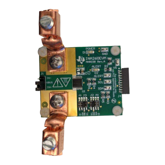
Page 26: Pcb Layout
INA260EVM Documentation www.ti.com PCB Layout Figure 22 shows the component layout for the INA260EVM PCB. Figure 22. INA260EVM PCB Top Layer (Component Side) INA260EVM-PDK and Software Tutorial SBOU180 – November 2016 Submit Documentation Feedback Copyright © 2016, Texas Instruments Incorporated... -
Page 27: Bill Of Materials
INA260EVM Documentation www.ti.com Bill of Materials Table 6 lists the bill of materials for the INA260EVM. Table 6. Bill of Materials: INA260EVM Item No. Ref Des Description Vendor/Mfr Part Number CAP, CERM, 1 µF, 50 V, +/- 10%, X7R, MuRata GRM21BR71H105KA12L 0805 D1, D2... - Page 28 STANDARD TERMS AND CONDITIONS FOR EVALUATION MODULES Delivery: TI delivers TI evaluation boards, kits, or modules, including demonstration software, components, and/or documentation which may be provided together or separately (collectively, an “EVM” or “EVMs”) to the User (“User”) in accordance with the terms and conditions set forth herein.
- Page 29 FCC Interference Statement for Class B EVM devices NOTE: This equipment has been tested and found to comply with the limits for a Class B digital device, pursuant to part 15 of the FCC Rules. These limits are designed to provide reasonable protection against harmful interference in a residential installation.
- Page 30 【無線電波を送信する製品の開発キットをお使いになる際の注意事項】 開発キットの中には技術基準適合証明を受けて いないものがあります。 技術適合証明を受けていないもののご使用に際しては、電波法遵守のため、以下のいずれかの 措置を取っていただく必要がありますのでご注意ください。 1. 電波法施行規則第6条第1項第1号に基づく平成18年3月28日総務省告示第173号で定められた電波暗室等の試験設備でご使用 いただく。 2. 実験局の免許を取得後ご使用いただく。 3. 技術基準適合証明を取得後ご使用いただく。 なお、本製品は、上記の「ご使用にあたっての注意」を譲渡先、移転先に通知しない限り、譲渡、移転できないものとします。 上記を遵守頂けない場合は、電波法の罰則が適用される可能性があることをご留意ください。 日本テキサス・イ ンスツルメンツ株式会社 東京都新宿区西新宿6丁目24番1号 西新宿三井ビル 3.3.3 Notice for EVMs for Power Line Communication: Please see http://www.tij.co.jp/lsds/ti_ja/general/eStore/notice_02.page 電力線搬送波通信についての開発キットをお使いになる際の注意事項については、次のところをご覧ください。http:/ /www.tij.co.jp/lsds/ti_ja/general/eStore/notice_02.page SPACER EVM Use Restrictions and Warnings: 4.1 EVMS ARE NOT FOR USE IN FUNCTIONAL SAFETY AND/OR SAFETY CRITICAL EVALUATIONS, INCLUDING BUT NOT LIMITED TO EVALUATIONS OF LIFE SUPPORT APPLICATIONS.
- Page 31 SPACER Disclaimers: 6.1 EXCEPT AS SET FORTH ABOVE, EVMS AND ANY WRITTEN DESIGN MATERIALS PROVIDED WITH THE EVM (AND THE DESIGN OF THE EVM ITSELF) ARE PROVIDED "AS IS" AND "WITH ALL FAULTS." TI DISCLAIMS ALL OTHER WARRANTIES, EXPRESS OR IMPLIED, REGARDING SUCH ITEMS, INCLUDING BUT NOT LIMITED TO ANY IMPLIED WARRANTIES OF MERCHANTABILITY OR FITNESS FOR A PARTICULAR PURPOSE OR NON-INFRINGEMENT OF ANY THIRD PARTY PATENTS, COPYRIGHTS, TRADE SECRETS OR OTHER INTELLECTUAL PROPERTY RIGHTS.
- Page 32 IMPORTANT NOTICE Texas Instruments Incorporated and its subsidiaries (TI) reserve the right to make corrections, enhancements, improvements and other changes to its semiconductor products and services per JESD46, latest issue, and to discontinue any product or service per JESD48, latest issue.
Need help?
Do you have a question about the INA260 and is the answer not in the manual?
Questions and answers