Table of Contents
Advertisement
Quick Links
August 2005
National Semiconductor
Rev F
Evaluation Board Instruction Manual
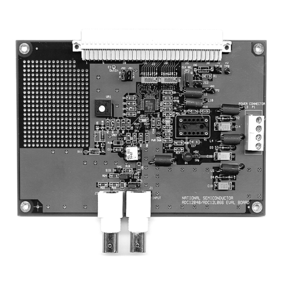
ADC12040 12-Bit, 40 Msps, 5 Volt, 380 mW A/D Converter
ADC12010 12-Bit, 10 Msps, 5 Volt, 160 mW A/D Converter
ADC12020 12-Bit, 20 Msps, 5 Volt, 185 mW A/D Converter
ADC12L063 12-Bit, 62 Msps, 3.3 Volt 354 mW A/D Converter
© 2001, 2002, 2003, 2004 National Semiconductor Corporation.
http://www.national.com
1
Advertisement
Table of Contents

Summary of Contents for National Semiconductor ADC12010
- Page 1 Evaluation Board Instruction Manual ADC12040 12-Bit, 40 Msps, 5 Volt, 380 mW A/D Converter ADC12010 12-Bit, 10 Msps, 5 Volt, 160 mW A/D Converter ADC12020 12-Bit, 20 Msps, 5 Volt, 185 mW A/D Converter ADC12L063 12-Bit, 62 Msps, 3.3 Volt 354 mW A/D Converter ©...
-
Page 2: Table Of Contents
6.0 Obtaining Best Results...6 6.1 Clock Jitter...6 6.2 Coherent Sampling...7 7.0 Evaluation Board Specifications ...8 8.0 Hardware Schematic ...9 9.0 Evaluation Board Bill of Materials...10 A1.0 Operating in the Computer Mode...12 A2.0 Summary Tables of Test Points and Connectors ...12 http://www.national.com... -
Page 3: Introduction
WaveVision software, operating under Microsoft Windows. Or use WAVEVSN BRD 4.0 when available on National's web site. Use the WaveVision2 program WaveVision 4.0 when available on National's web site. -
Page 4: Quick Start
P1. Supply +5V at pin 3 of P1 to supply the Digital Interface board. Supply +3.3V to pin 1 for the ADC12L063, or +5V to pin 1 for the ADC12010, ADC12020 and the ADC12040. Pin 2 is ground. Use VR1 to set the reference voltage (V REF ), which 2.0V... -
Page 5: Dual Input
Figure 1, the reference circuit will generate a nominal reference voltage in the range of 0 to 2.4 Volts for the ADC12040, ADC12010 and ADC12020 or 0 to 1.2 Volts for the ADC12L063. The ADC12040, ADC12010 and ADC12020 are specified to operate with V REF in the range of 1.0 to 2.4 V, with a... -
Page 6: Obtaining Best Results
The problem of Figure 3 is obvious, but it is not as easy to see the problem in Figure 4, where the only thing we see is small excursions beyond the normal envelope. Compare Figure 3 and Figure 4 with Figure 5. http://www.national.com... -
Page 7: Coherent Sampling
Board Size: 6.5" x 3.5" (16.5 cm x 8.9 cm) Power Requirements: +5.0V, 100 mA (ADC12040 / ADC12010 / ADC12020) or +3.3V, 120 mA (ADC12L063) +5V @ 30 mA / 1A (see Sect 4.6) Clock Frequency Range: 1.0 MHz to 40 MHz or 60 MHz... -
Page 8: Hardware Schematic
AGND DGND DGND http://www.national.com... -
Page 9: Evaluation Board Bill Of Materials
RP1, RP2 TP1, TP2, TP3, TP4, TP5, TP6, TP7, TP8, TP9, TP20 TP10 Part 1 uF 0.1 uF 22 pF (330 pF for ADC12010 / 12020) 22 pF 33 uF, 6.3V not populated is diode D15 RED LED 1N4001 LM4041BIZ-2.5... -
Page 10: A1.0 Operating In The Computer Mode
Use Clock signal from J2 pin B23 Connect 2-3 Use crystal oscillator Y1 JP3 Jumper - ADC Input Select Connect 1-2 Use single J1 Input Connect 2-3 Mix J1 & J3 Inputs (must also have JP4 pins 1 & 2 shorted) http://www.national.com... - Page 11 ADC Output Enable C12 (not used) External clock input Reserved, signal B22, C22, C23 Reserved, power A25, A26, B25, B26, C25, C26 (+5V Logic Power Supply to Digital Interface Board ) Reserved, power A29, B29, C29 Reserved, power A32, B32, C32 http://www.national.com...
-
Page 12: Life Support Policy
Email: support@nsc.com www.national.com National does not assume any responsibility for any circuitry described, no circuit patent licenses are implied and National reserves the right at any time without notice to change said circuitry and specifications. 2. A critical component is any component in a life...


Need help?
Do you have a question about the ADC12010 and is the answer not in the manual?
Questions and answers